Table of Contents
Advertisement
Quick Links
Advertisement
Table of Contents

Related Manuals for EK-Quantum LGA1700


Summary of Contents for EK-Quantum LGA1700
- Page 1 EK-Quantum Velocity Backplate - LGA1700 USER GUIDE...
-
Page 2: Table Of Contents
TABLE OF CONTENTS PACKAGED CONTENTS BACKPLATE DIMENSIONS REMOVING THE MOTHERBOARD ATTACHING THE BACKPLATE TO THE MOTHERBOARD INSTALLING FOUR (4) M3 THUMB SCREWS ONTO YOUR MOTHERBOARD INSTALLING THE WATER BLOCK CONNECTING THE RGB LED STRIP (Optional) CONNECTING THE RGB LED STRIP CONNECTING THE D-RGB LED STRIP SUPPORT AND SERVICE SOCIAL MEDIA... -
Page 3: Packaged Contents
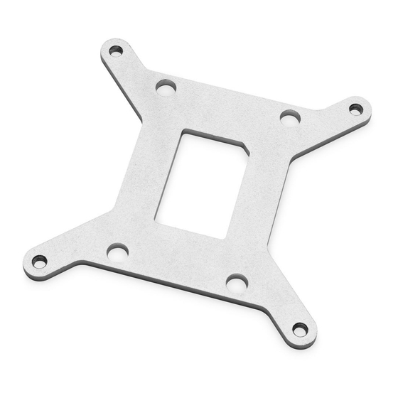
PACKAGED CONTENTS EAN: 3831109861691 103786 103785 Gasket backplate CPU LGA 1700 (1pc) Metal backplate CPU LGA 1700 (1pc) BACKPLATE DIMENSIONS 93 mm - 3 -... -
Page 4: Removing The Motherboard
REMOVING THE MOTHERBOARD If your PC case doesnt have a cutout from the bottom CPU side of the motherboard, you will first need to remove the motherboard from your computer and place it on an even surface with the front facing down. ATTACHING THE BACKPLATE TO THE MOTHERBOARD Make sure to orientate the rubber gasket to fit past the CPU socket ILM backplate. -
Page 5: Installing Four (4) M3 Thumb Screws Onto Your Motherboard
INSTALLING FOUR (4) M3 THUMB SCREWS ONTO YOUR MOTHERBOARD It is mandatory to put a 0.7mm plastic washer underneath each of the M3 thumb screws. Tighten the screws to the metal backplate M3 THUMB SCREW until you reach the end of the thread. It is not recommended to use tools (such as pliers). - Page 6 STEP 2 THUMB NUT Align the water block over the mounting screws on the motherboard with the pre-installed CPU. COILED SPRING Before proceeding with the installation, it is mandatory to remove the protective foil from the backside of the water block. Place an enclosed compression spring and thumb nut over each M3 thumb screw.
-
Page 7: Connecting The Rgb Led Strip (Optional)
CONNECTING THE RGB LED STRIP (Optional) RGB LED CONNECTOR CONNECTING THE RGB LED STRIP STEP 1 Plug the 4-pin connector from the water block and fan’s RGB LED light to the RGB HEADER on the motherboard. The LED will work if the pin layout on the header is as follows: +12V G R B. -
Page 8: Connecting The D-Rgb Led Strip
CONNECTING THE D-RGB LED STRIP STEP 1 Plug the 4-pin connector from the water block’s D-RGB LED light to the DRGB HEADER on the motherboard. The LED will work if the pin layout on the header is as follows: +5V, Digital, empty, Ground. Please ensure that the arrow indicated on the connector is plugged into the +5V line as indicated on your motherboard. -
Page 9: Support And Service
SUPPORT AND SERVICE In case you need assistance or wish to order spare parts or a new mounting mechanism, please contact: https://www.ekwb.com/customer-support/ EKWB d.o.o. Pod lipami 18 1218 Komenda Slovenia - EU SOCIAL MEDIA EKWaterBlocks @EKWaterBlocks ekwaterblocks EKWBofficial ekwaterblocks...
Need help?
Do you have a question about the LGA1700 and is the answer not in the manual?
Questions and answers