Sign In
Upload
Download
Add to my manuals
Delete from my manuals
Share
URL of this page:
HTML Link:
Bookmark this page
Add
Manual will be automatically added to "My Manuals"
Print this page
×
Bookmark added
×
Added to my manuals
Manuals
Brands
Emtek Manuals
Locks
Classic
Installation & programming manual
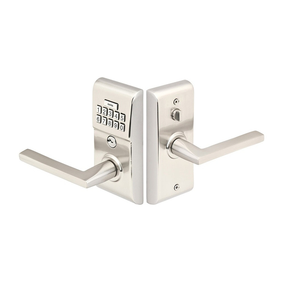
Emtek Classic Installation & Programming Manual
Electronic deadbolt locksets
Hide thumbs
1
2
3
4
5
6
7
8
9
10
11
12
page
of
12
Go
/
12
Bookmarks
Advertisement
Quick Links
Download this manual
Installation & Programming Guide
Classic & Modern Styles
Electronic Deadbolt Locksets
Classic Style
Modern Style
Previous
Page
Next
Page
1
2
3
4
5
Advertisement
Need help?
Do you have a question about the Classic and is the answer not in the manual?
Ask a question
Questions and answers
Related Manuals for Emtek Classic
Locks Emtek Modern Style Installation & Programming Manual
Electronic keypad lever locksets (36 pages)
Locks Emtek CF Mechanism Installation Manual
Passage & privacy locksets (12 pages)
Locks Emtek CF 2.0 Installation Manual
Passage & privacy locksets (12 pages)
Locks Emtek EMpowered Smart Lock Manual
Connected by august (59 pages)
Locks Emtek EMPOWERED 2 Touch Manual
Key free deadbolt (36 pages)
Locks Emtek EMPowered in8-empwrunty Manual
Motorized touchscreen works with yale access. keypad smart lock deadbolt (29 pages)
Locks Emtek Keyed Pocket Door Mortise Lock Installation Manual
(2 pages)
Locks Emtek EMPowered EMP7990RKUS15 Manual
Motorized smart lock upgrade works with yale access keyed sideplate (25 pages)
Locks Emtek Adams Handleset EMPowered EMP4414FRKUS10B-2 Manual
Motorized smart lock upgrade works with yale access sectional entry set (25 pages)
This manual is also suitable for:
Modern
Print
Rename the bookmark
Delete bookmark?
Delete from my manuals?
Login
Sign In
OR
Sign in with Facebook
Sign in with Google
Upload manual
Upload from disk
Upload from URL


Need help?
Do you have a question about the Classic and is the answer not in the manual?
Questions and answers