Table of Contents
Advertisement
Quick Links
Advertisement
Table of Contents

Related Manuals for Burkert MS08


Summary of Contents for Burkert MS08
- Page 1 Type MS08 SAC254 Sensor Operating Instructions...
- Page 2 We reserve the right to make technical changes without notice. © Bürkert SAS, 2021 Operating Instructions 2109/00_EU-ML 00572428 / Original EN...
-
Page 3: Table Of Contents
5 Installation .............................. 23 Safety instructions .......................... 23 Installing procedure ........................ 23 6 Electrical connection.......................... 25 Connection plan MS08 ........................ 25 Connection plan ME63 ........................ 26 Assignment of the connections ...................... 26 Supply voltage .......................... 28 M12 8 pins SAC254 Sensor connection .................. 28 7 Commissioning ............................ 30... - Page 4 Type MS08 Table of contents Manufacturer calibration......................... 30 Path length check........................... 30 Install the micro SD card ........................ 31 Transfer data to or from another product.................. 32 8 Setting and operation.......................... 34 Safety instructions .......................... 34 Setting tools and setting software.................... 34 Description of the user interface ....................
- Page 5 Type MS08 Table of contents 12.7 Address of a product connected to büS .................. 55 12.8 Change the address of the product connected to a CANopen fieldbus ........ 55 12.9 Read the actually used CANopen address (Node ID) .............. 55 12.10 Set the digital communication for büS or for a CANopen fieldbus ..........
- Page 6 16.1.3 Messages [FUNCTION CHECK]: function check............... 77 16.1.4 Messages [MAINTENANCE]: maintenance required ............ 78 16.1.5 Messages [INFO]: information ................... 80 17 Spare parts and accessories ........................ 81 17.1 MS08 SAC254 Sensor accessories.................... 81 18 Uninstallation ............................ 82 18.1 Safety instructions .......................... 82 18.2 Uninstalling procedure........................ 82 19 Logistic .............................. 83...
-
Page 7: About This Document
▪ Before starting any work on the product, read and observe the respective sections of the document. ▪ Keep the document available for reference and give it to the next user. ▪ Contact the Bürkert sales office for any questions. Further information concerning the product at country.burkert.com. Manufacturer Bürkert SAS... -
Page 8: Terms And Abbreviations
Type MS08 About this document Terms and abbreviations The terms and abbreviations are used in this document to refer to following definitions. Product MS08 ▪ Photometer, digital büS Bürkert system bus, a communication bus developed by Bürkert and based on the... -
Page 9: Safety Instructions
MS08 is used exclusively for the implementation of SAC or transmission measurements as described in this manual. The product has been developed for use in industrial an municipal water treatment plants. The ME63 Sensor Interface is used to connect the Sensor Types MS08 and MS09 into Bürkert büS net- works. - Page 10 Type MS08 Safety instructions To prevent injuries and product damage, observe the following: ▶ Install the product according to the regulations applicable in the respective country. ▶ Make sure only trained technicians carry out installation and maintenance work. ▶ Secure the product or system to prevent unintentional activation.
- Page 11 Type MS08 Safety instructions DANGER! Bürkert does not guarantee the plausibility of the measured values. The user is always responsible for the monitoring and interpretation of the measured values. CAUTION! Electrostatically sensitive components and assemblies. The product contains electronic components that are susceptible to the effects of electrostatic dischar- ging (ESD).
-
Page 12: Product Description
Type MS08 Product description PRODUCT DESCRIPTION Design The MS08 consists of the following components: Fig. 1: MS08 components 1 SAC254 Sensor 2 Flow cell 3 Connecting cable 4 ME63 Sensor interface 3.1.1 ME63 Sensor Interface Fig. 2: View of ME63 type 1 X1... -
Page 13: Sac254 Sensor
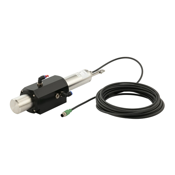
Type MS08 Product description 9 Product status indicator 10 Cover with 2 screws, slot for micro SD card 11 X01, X02: D-coded connection 12 X03 (IN), X04 (OUT): L-coded connection, 24 V DC 13 Earth connection 3.1.2 SAC254 Sensor Fig. 3: View of SAC254 Sensor Fig. 4: SAC254 Sensor dimensions... -
Page 14: Display Elements
Type MS08 Product description Fig. 6: Flow cell dimensions Display elements Type ME63 has LEDs for diagnostics on the product status: Fig. 7: Display elements for ME63 type 1 Product status indicator. The indicator op- 2 Communication status indicator 1. The in- erates according to NAMUR NE 107. - Page 15 Type MS08 Product description The colour of the product status indicator gives the following pieces of information: ▪ Whether product diagnostics are active or not. Diagnostics are active on the product and cannot be de- activated. ▪ If product diagnostics are active, then the product status indicator shows whether diagnostics events have been generated or not.
-
Page 16: Markings
To solve a problem indicated by the product status indicator, refer to chapter: Troubleshooting [} 75]. Markings 3.3.1 Type label 3.3.1.1 ME63 Sensor Interface Fig. 8: ME63 Label 3.3.1.2 SAC254 Sensor Fig. 9: SAC254 Sensor Label 3.3.1.3 Flow cell Fig. 10: MS08 Flow cell Label... -
Page 17: Conformity Marking
Operating principle The ME63 Sensor Interface represents the central control unit for MS08 and MS09. The ME63 Sensor Interface is an additional interface for büS devices. The ME63 Sensor Interface ex- changes data with the SAC254 Sensor on Ethernet communication. - Page 18 Type MS08 Product description 3 Optical path 4 Mirror 5 Lenses 6 Light sources The SAC254 Sensor essentially consists of four parts (See figure above): ▪ a defined light source that consists of two LEDs of different wavelengths – wavelength LED 1: 254 nm –...
- Page 19 Type MS08 Product description spectral absorption coefficient in [1/m] = Abs − Abs Fig. 16: Equation 4 - Calculation of the spectral absorption coefficient with measured absorbance values where: Abs254 absorption in [1/m] Abs530 absorption in [1/m] Parameters The SAC254 Sensor uses two different LEDs for long-term stable measurements of SAC values. The follow- ing parameters can be measured or derived with the SAC254 Sensor, see table below.
-
Page 20: Technical Data
Type MS08 Technical data TECHNICAL DATA Conformity The product complies with the EU directives according to the EU declaration of conformity (if applicable). The applied standards, which verify conformity with the EU directives, can be found on the EU type examin- ation certificate and/or the EU declaration of conformity (if applicable). -
Page 21: Dimensions, Weight
Type MS08 Technical data Dimensions, weight Refer to the data sheet of the related product. Performance data Parameters , CODeq, BODeq, TOCeq, Turb 530 Measurement range see parameter list below Measurement accuracy 0.2 % Turbidity compensation at 530 nm Reaction time T100 4 s... -
Page 22: Fluid Data
Type MS08 Technical data Fluid data Operating fluid Aquaeous solutions Type of liquids Aqueous fluids with water qualities equal or better than drinking water Sample temperature +2...+40 °C Inflow velocity 0.1...10 m/s (with flow cell 2...4 L/mn) Fluid pressure ▪ 3 bar without flow cell ▪... -
Page 23: Installation
Type MS08 Installation INSTALLATION Safety instructions WARNING! Risk of injury due to improper installation. ▶ Only trained technicians may perform installation work. ▶ Perform installation work using suitable tools only. CAUTION! Malfunction due to electrostatic discharge. Electrostatic discharge on the product may cause malfunctions. - Page 24 To remove the hoses, press on the locking ring on the hose connector and carefully pull the hose away. ATTENTION! The flow cell cannot be combined with the compressed-air cleaning. Step 3: Connect the SAC254 Sensor to the ME63 Sensor Interface For connecting the SAC254 Sensor to the ME63 Sensor Interface, refer ro chapter Connection plan MS08 [} 25].
-
Page 25: Electrical Connection
Electrical connection ELECTRICAL CONNECTION Connection plan MS08 Fig. 18: Connection plan MS08 1 ME63 Sensor interface 2 MS08 Ethernet cable (blue colour): X01 or 3 Cable 4 SAC254 Sensor 5 Flow cell 6 MS08 power supply cable: X1–X3, X5–X8 7 M12 terminating resistor: X1–X3, X5–X8 8 Burkert büS input (CAN + power supply): X4... -
Page 26: Connection Plan Me63
Electrical connection Connection plan ME63 Fig. 19: Connections ME63 Sensor interface (detail) 2 MS08 Ethernet cable (blue colour): X01 or 6 MS08 power supply cable: X1–X3, X5–X8 7 M12 terminating resistor: X1–X3, X5–X8 8 Burkert büS input (CAN + power supply): X4... - Page 27 Type MS08 Electrical connection Port Function Pin 1 Pin 2 Pin 3 Pin 4 Pin 5 X4 (IN) CAN + power CAN_GND 24 V CAN_H CAN_L supply Tab. 13: Assignment of the connections Assignment Function Send data + Receive data + Send data - Receive data - Tab. 14: Connections M12, X01, X02 (socket), D-coded...
-
Page 28: Supply Voltage
Type MS08 Electrical connection Supply voltage Fig. 20: Supply options 1 Supply via A-coded connection, max. 4 A, 2 Return flow is prevented via reverse protec- automatic detection tion 3 24 V/32 A source 1 4 24 V/32 A source 2 5 Supply via L-coded connection, max. - Page 29 Type MS08 Electrical connection Assignment Function RS-232 RX / RS-485 A (commands) RS-232 TX / RS-485 B (data) ETH_RX- ETH_RX+ ETH_TX- ETH_TX+ Ground (Power + Ser. In- terface) Power (24 VD C) Tab. 17: SAC254 Sensor: M12 8 pins connections Ensure correct polarity of the operating voltage or otherwise the sensor may be damaged.
-
Page 30: Commissioning
Type MS08 Commissioning COMMISSIONING Safety instructions WARNING! Risk of injury from improper operation. Improper operation can lead to injuries and damage to the product and its environment. ▶ Before commissioning, make sure that the operating personnel are familiar with, and fully understand the content of the Operating Instructions. -
Page 31: Install The Micro Sd Card
Type MS08 Commissioning Optimal range Allowed range Out of specific- ation range Min. Max. Min. Max. Min. A[AU] 0.005 >2 Path 1 mm [1/m] 5 1500 1500 2000 2000 Path 2 mm [1/m] 2.5 1000 1000 Path 5 mm [1/m] 1 Path 10 mm [1/ Path 50 mm [1/... -
Page 32: Transfer Data To Or From Another Product
Type MS08 Commissioning Open the micro SD card slot: Unfasten the 2 screws using a cross-tip screwdriver and open the cover. Insert the micro SD card: Slide the micro SD card into the card slot. Ensure that the micro SD card locks into position. - Page 33 Type MS08 Commissioning Step 4: Restart the product Please note that a newly installed micro SD card is checked for the presence of existing data. Refer to chapter Install the micro SD card [} 31]...
-
Page 34: Setting And Operation
▪ the Type ME21 touchscreen of the Type 8905 system. To get general information about the Type ME21 touchscreen, refer to the Type ME25 Operating Instructions that are available on the CD delivered with the system and that are also available at country.burkert.com. These Operating Instructions describe the product-specific settings that are made with the Type ME21 touchscreen. -
Page 35: Available Login User Levels
Type MS08 Setting and operation ▪ the product functions. Each function has 3 menus. Refer to chapter Product functions and menus [} 36]. ▪ the Messages overview, overview of the messages that are related to both the system and the product. -
Page 36: Product Functions And Menus
Type MS08 Setting and operation Product functions and menus The product has 2 functions and each function has 3 menus. To access the product functions and the menus, do the following procedure: Press that is located under the touchscreen. Select < or > to display the Device view. -
Page 37: Sensor - Parameter
Type MS08 Sensor - Parameter SENSOR - PARAMETER Go to device SAC254 Sensor > function Sensor > tab Parameter. Detailed view Parameter Setting Sensor Select the type of sensor connected to the ME63 interface. Measure interval Set the interval for the automatic measurements. -
Page 38: Set The Interval For The Automatic Measurements
Sensor > tab Parameter. Select Sensor. Select the sensor type from the drop-down list: For the MS08, select SAC. After changing the sensor type, the device has to be restarted. The device restarts with the selected sensor type. Set the interval for the automatic measurements... -
Page 39: Monitor The Values Of The Water Sample
Type MS08 Sensor - Parameter Value Description Unit of offset ▪ g/l (grams per liter) CODeq Chemical oxygen demand ▪ mg/l (milligrams per liter) BODeq Biochemical oxygen demand ▪ µg/l (micrograms per liter) TOCeq Total Organic Carbon ▪ ppm (parts per million) ▪... -
Page 40: Freeze The Values Transmitted On The Fieldbus
Type MS08 Sensor - Parameter ▪ ▪ Configure and activate the warning limits of the values Make sure that the login user level is Installer. Refer to chapter Available login user levels [} 35]. Go to device SAC254 Sensor > function Sensor >... -
Page 41: Manual Freeze
Type MS08 Sensor - Parameter ▪ If you want to automatically freeze the values, for example with a special event that is considered as a trigger, then refer to Automatic freeze [} 41]. Example for a special event that is considered as a trig- ger: Cleaning operation of the product with the Type MZ20 cleaning system. -
Page 42: Change The Binary Event For The Automatic Freeze
Type MS08 Sensor - Parameter Select Hold value. Choose the values to be sent on the fieldbus If you want to send the last-measured values, then proceed as follows: Select Action > Last values. If you want to send user-specific values, then proceed as follows:... -
Page 43: Stop The Manual Freeze Or The Automatic Freeze
Type MS08 Sensor - Parameter Access to parameter Hold value Make sure that the login user level is Installer. Refer to chapter Available login user levels [} 35]. Go to device SAC254 Sensor > function Sensor > tab Parameter. Select Hold value. -
Page 44: Sensor - Diagnostics
Type MS08 Sensor - Diagnostics SENSOR - DIAGNOSTICS Go to device SAC254 Sensor > function Sensor > tab Diagnostics. Detailed View Diagnostics In these menus, the current values are displayed, not set. Setting General Information Read information about the sensor. -
Page 45: Check Sensor Information
Type MS08 Sensor - Diagnostics Setting Light intensity 530nm Tab. 23: Settings in the “Sensor” configuration area, diagnostics detailed view Detailed view Diagnostics The menu items are detailed in the following chapters: ▪ General Information, refer to chapter Check sensor information [} 45]. -
Page 46: Check Measured Values
Type MS08 Sensor - Diagnostics 10.3 Check measured values The values displayed under Measure values show information about the values measured by the sensor. The displayed values are read-only. Go to device SAC254 Sensor > function Sensor > tab Diagnostics. -
Page 47: Sensor - Maintenance
Type MS08 Sensor - Maintenance SENSOR - MAINTENANCE Go to device SAC254 Sensor > function Sensor > tab Maintenance. Detailed view Maintenance Setting Simulation Status Start or stop the simulation mode and enter simulated data. Start measurement Wizard to manually start a measurement. -
Page 48: Manually Start A Measurement
Type MS08 Sensor - Maintenance ▪ TOCeq: Total Organic Carbon ▪ SQI: Quality index To start the simulation mode, do the following procedure: Go to device SAC254 Sensor > function Sensor > tab Maintenance. Select Simulation > Status > On. -
Page 49: Restore The Previous Calibration
Type MS08 Sensor - Maintenance Perform calibration To perform the calibration, do the following procedure: Make sure that the login user level is Installer. Refer to chapter Available login user levels [} 35]. Go to device SAC254 Sensor > function Sensor >... -
Page 50: Plan The Calibrations
Type MS08 Sensor - Maintenance 11.6 Plan the calibrations Go to device SAC254 Sensor > function Sensor > tab Maintenance. Select Calibration schedule. ▪ The field Last calibration indicates the date of the last calibration procedure that has succeeded. ▪ The field Next calibration indicates the date of the next calibration procedure that must be done. - Page 51 Type MS08 Sensor - Maintenance Values are updated.
-
Page 52: General Settings - Parameter
Type MS08 General Settings - Parameter GENERAL SETTINGS - PARAMETER Go to device SAC254 Sensor > function General settings > tab Parameter. Detailed view Parameter Setting Status LED Mode büS Configuration of the büS interface Displayed name For display and Bürkert Communicator Location Specify location displayed for the device. -
Page 53: Set The Colours And Behaviour Of The Device Status Led
Type MS08 General Settings - Parameter The menu items are detailed in the following chapters: ▪ Status LED, refer to chapter Set the colours and behaviour of the device status LED [} 53]. ▪ büS, refer to chapter Enter a name for the product [} 53],... -
Page 54: Enter The Location Of The Product
Type MS08 General Settings - Parameter 12.3 Enter the location of the product The entered location will be shown on any display connected to büS. To enter the information where the product is located, do the following procedure: Make sure that the login user level is Installer. Refer to chapter Available login user levels [} 35]. -
Page 55: Address Of A Product Connected To Büs
Type MS08 General Settings - Parameter Make sure that the login user level is Installer. Refer to chapter Available login user levels [} 35]. Go to device SAC254 Sensor > function General settings > tab Parameter. Select büS > Advanced >... -
Page 56: Set The Canopen Status
Type MS08 General Settings - Parameter Select büS > Advanced > mode. Select the operating mode büS CANopen from the drop-down list. Validate with Apply. The operating mode of the digital communication is changed. If the operating mode of the digital communication is set to büS... -
Page 57: Change The Time To Check The Presence Of A Participant On The Fieldbus
Type MS08 General Settings - Parameter Select Standalone. Validate with Apply. Restart the product to take the operating mode of digital communication into account. The PDOs are no more sent to the connected fieldbus. 12.14 Change the time to check the presence of a participant on the fieldbus Bürkert recommends not to change the parameter... -
Page 58: Monitor The Device Temperature
Type MS08 General Settings - Parameter 12.16 Monitor the device temperature The parameters at Alarm limits make it possible to monitor the device temperature and issue a warning or error in case of too low or too high temperature. The alarm limits for warnings can be set by the user. The alarm limits for errors and hysteresis are read- only. - Page 59 Type MS08 General Settings - Parameter By default, the diagnostics are enabled. The product status are shown according to Table Product status when the diagnostics are enabled [} 59]. Product status indicator Colour code (for Displayed sym- Description Meaning a PLC)
-
Page 60: Set The Transmission Time Between 2 Values Of A Pdo
Type MS08 General Settings - Parameter Product status indicator Colour code (for Displayed sym- Description Meaning a PLC) Flashing rapidly Identification The product is selected using a man-machine interface, for example the Bürkert Communic- ator software. Tab. 34: Product status when the diagnostics are disabled 12.18... -
Page 61: Restore All Pdos To Their Default Values
Type MS08 General Settings - Parameter Name Data type Unit SI Range Event timer Inhibit time (ms) (ms) TOCeq (Total Organic Car- REAL32 0…880 5000 bon) Tab. 37: PDO 3 - Transmitted data and their default values Multiplexed PDO Name Data type... -
Page 62: General Settings - Diagnostics
Type MS08 General Settings - Diagnostics GENERAL SETTINGS - DIAGNOSTICS Go to device SAC254 Sensor > function General settings > tab Diagnostics. Detailed view Diagnostics In these menus, the current values are displayed, not set. Setting Device status Operating duration... -
Page 63: Read The Current Device Temperature
Type MS08 General Settings - Diagnostics ▪ büS status, refer to chapter Read the number of current receive errors [} 64], Read the maximum number of receive errors since the last power-up of the device [} 64], Read the number of current transmit errors [} 64],... -
Page 64: Check The Presence Of The Memory Card
Type MS08 General Settings - Diagnostics Go to device SAC254 Sensor > function General settings > tab Diagnostics. Select Device status. Read the value of the parameter Device boot counter. 13.6 Check the presence of the memory card You can check if the memory card is inserted in its product slot without removing the product from the backplane. -
Page 65: Read The Maximum Number Of Transmit Errors Since The Last Power-Up Of The Device
Type MS08 General Settings - Diagnostics 13.11 Read the maximum number of transmit errors since the last power-up of the device Make sure that the login user level is at least Advanced user. Refer to chapter Available login user levels [} 35]. - Page 66 Type MS08 General Settings - Diagnostics Sensor | General settings | Diagnostics 19 Messages Back to previous view Symbol is bright: the event is 20.08.2019 - 13:19:21 still active Message büS event: producer not found 20.08.2019 - 13:19:25 Event message 20.08.2019 - 11:36:12...
-
Page 67: General Settings - Maintenance
Type MS08 General Settings - Maintenance GENERAL SETTINGS - MAINTENANCE Go to device SAC254 Sensor > function General settings > tab Maintenance. Detailed view Maintenance In these menus, the current values are displayed, not set. Setting Device information Displayed name Only displayed if a name was entered in the menu of the same name for the Parameter detailed view. -
Page 68: Restart The Product
Type MS08 General Settings - Maintenance Parameter Description Serial number Product serial number Firmware ident. Number Article number of the product firmware Firmware version Version number of the product firmware büS version büS version number Hardware version Version number of the product hardware... -
Page 69: Maintenance
Type MS08 Maintenance MAINTENANCE 15.1 Safety instructions DANGER! Risk of injury from electric shocks. ▶ Before working on the installation or product, switch off the power supply. Make sure that nobody can switch the power supply on. ▶ Observe all applicable accident protection and all applicable safety regulations for electrical equipment. -
Page 70: Replace The Memory Card
Type MS08 Maintenance 15.3 Replace the memory card For a description of how to replace the memory card, refer to chapter Transfer data to or from another product [} 32]. 15.4 Cleaning and upkeep To ensure an error-free and reliable measurement, the product should be periodically checked and main- tained. -
Page 71: Cleaning The Measuring Window
Type MS08 Maintenance 15.4.2 Cleaning the measuring window Make sure that you do not touch the window surface with your fingers! Clean the window with a few drops of acetone and a lint-free cloth, a clean paper towel or a special optical paper. -
Page 72: Checking The Zero Value
Type MS08 Maintenance ATTENTION! Damage caused by improper cleaning is not covered by the warranty! Immerse the sensor in the prepared measurement container with ultra-pure water so that the measuring windows are completely covered by water. The sensors should be positioned diagonally in the measurement container, if at all possible, to prevent very small, almost invisible air bubbles collecting at the top of the measuring window. -
Page 73: Checking The Maximum Value
Type MS08 Maintenance General Information: ▪ Do not touch the part of the sensor which has been submerged in the ultra-pure water with your hands during the sensor check unless you are wearing gloves. ▪ Be sure to use highly pure water (ultra pure, resistance of 18.2 MΩcm) or distilled water. - Page 74 Type MS08 Maintenance Check the sensor settings. If the settings are OK and the value is still over 3% then contact Bürkert.
-
Page 75: Troubleshooting
Type MS08 Troubleshooting TROUBLESHOOTING 16.1 Troubleshooting with messages Messages can only be generated if the diagnostics are enabled. Refer to chapter Disable or enable the dia- gnostics. When a message is generated, the following actions are carried out: ▪ The symbol is displayed in the information bar. -
Page 76: Messages [Out Of Specification]: Out Of Specification
Type MS08 Troubleshooting 16.1.1.3 Message Sensor error (internal error). Contact the service for your device Product status symbol Possible cause A sensor internal error occurred. What to do? Check the wiring. Restart the sensor and the ME63 interface. If the message is still there, send the sensor back to Bürkert. -
Page 77: Messages [Function Check]: Function Check
Type MS08 Troubleshooting 16.1.2.2 Message Warning: Quality of measurement limited (SAC). Check sensor and process Product status symbol Possible cause The SAC (Spectral Absorption Coefficient) value is under the pro- grammed warning threshold level. What to do? Check the sensor. -
Page 78: Messages [Maintenance]: Maintenance Required
Type MS08 Troubleshooting 16.1.3.2 Message Hold mode active Product status symbol Possible cause The values that are sent by the product on the fieldbus are tempor- arily frozen. Refer to chapter Freeze the values transmitted on the fieldbus [} 40]. What to do? Wait until the binary event is deactivated. - Page 79 Type MS08 Troubleshooting 16.1.4.4 Message Deviation from default settings detected, resets to default settings Product status symbol Possible cause The default settings have been modified. They will be overwritten by the ME63 interface. What to do? No action. 16.1.4.5 Message Last calibration is older than %1 days.
-
Page 80: Messages [Info]: Information
Type MS08 Troubleshooting 16.1.5 Messages [INFO]: information If the message displayed on your product is not explained in the Operating Instructions, contact Bürk- ert. 16.1.5.1 Message Sensor error (data transfer failed). Contact the service for your device Product status symbol Possible cause A file transfer error occurred. -
Page 81: Spare Parts And Accessories
Y-distributor, 0.7 m cable with M12 plug) SAC254 sensor 00572114 Flow Cell SAC254 50 mm pathlength 00572116 MS08 büS interface 00572118 Bubble trap 00568492 Hose connector, angled, 1/4" 00782348 5 m hose tubing 6/4 mm 00567793 Micro SD card 00774087 Tab. 46: MS08 SAC254 Sensor: Accessories... -
Page 82: Uninstallation
Type MS08 Uninstallation UNINSTALLATION 18.1 Safety instructions WARNING! Risk of injury due to improper installation. ▶ Only trained technicians may perform installation work. ▶ Perform installation work using suitable tools only. CAUTION! Malfunction due to electrostatic discharge. Electrostatic discharge on the product may cause malfunctions. -
Page 83: Logistic
Type MS08 Logistic LOGISTIC 19.1 Transport ATTENTION! Transport damage. If the product is not protected in transport, then the product can be damaged. ▶ Remove cables, connectors, product-external filters and installation equipment. ▶ Protect the electrical interfaces with protective plugs.
Need help?
Do you have a question about the MS08 and is the answer not in the manual?
Questions and answers