Burkert 8741 Operating Instructions Manual
Mass flow meter / mass flow controller
Hide thumbs
Also See for 8741:
- Operating instructions manual (44 pages) ,
- Operating instructions manual (46 pages)
Table of Contents
Advertisement
Quick Links
Advertisement
Table of Contents

Related Manuals for Burkert 8741


Summary of Contents for Burkert 8741
- Page 1 Type 8741 Mass flow meter / Mass flow controller Operating Instructions...
- Page 2 We reserve the right to make technical changes without notice. © Bürkert SAS, 2017 - 2024 Operating Instructions 2402/04 00568707 / Original EN...
-
Page 3: Table Of Contents
Type 8741 Table of contents TABLE OF CONTENTS 1 About this document.......................... 6 Manufacturer............................. 6 Symbols ............................ 6 Terms and abbreviations ........................ 7 2 Safety ................................ 8 Intended use ............................. 8 Safety instructions .......................... 8 3 Product description .......................... 11 Product overview .......................... 11 Product identification ........................ 14 3.2.1 Type label .......................... 14 3.2.2... - Page 4 Type 8741 Table of contents 6 Electrical connection.......................... 30 Additional documentation ....................... 30 Wire the variant büS /CANopen...................... 30 6.2.1 With büS extension cables from Bürkert ................ 30 6.2.2 With büS cables from Bürkert.................... 30 6.2.3 With CANopen cables...................... 31 Wire the variant Analogue with D-sub DE-9 male connector ............ 32 6.3.1...
- Page 5 Type 8741 Table of contents 10.2 Status indicator is orange ....................... 56 10.3 Status indicator is yellow ........................ 58 10.4 Status indicator is blue ........................ 61 10.5 Status indicator is off ........................ 61 10.6 Status indicator goes out periodically..................... 61 10.7 Replacement device adopts none of the values from the defective device ........ 61 10.8 Replacement device does not adopt all of the values from the defective device ...... 61...
-
Page 6: About This Document
Before starting any work on the product, read and observe the respective sections of the document. Keep the document available for reference and give it to the next user. Contact the Bürkert sales office for any questions. Further information concerning the product at country.burkert.com. Manufacturer Bürkert SAS... -
Page 7: Terms And Abbreviations
Type 8741 About this document Terms and abbreviations The terms and abbreviations are used in this document to refer to following definitions. Device Type 8741 Mass flow meter Mass flow controller büS Bürkert system bus, a communication bus developed by Bürkert and based on the... -
Page 8: Safety
Type 8741 Safety SAFETY Intended use The device MFM is designed to measure the mass flow rate of clean and dry gases. The device MFC is designed to measure and regulate the mass flow rate of clean and dry gases. - Page 9 Type 8741 Safety Meet the requirements specified by EN 61340-5-1 to minimise or avoid the possibility of damage caused by a sudden electrostatic discharge. Do not touch electronic components when the supply voltage is connected. Electric shock due to electrical components Touching live parts can result in severe electric shock.
- Page 10 Type 8741 Safety Medium under pressure Medium under pressure can seriously injure people. In the event of overpressure or pressure surges, the device or lines can burst. Pneumatic lines that are defective or not securely fastened can come loose and swing around.
-
Page 11: Product Description
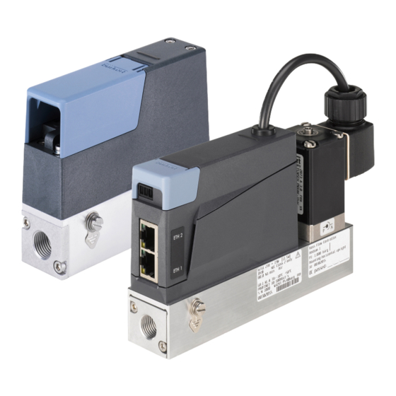
Type 8741 Product description PRODUCT DESCRIPTION The device is used for ultimate precision in the feedback control of medium. This document describes following variant: MFM Analogue MFM büS/CANopen MFM Industrial Ethernet MFM RS485/Modbus RTU MFC Analogue with proportional valve MFC büS/CANopen with proportional valve... - Page 12 Type 8741 Product description MFM büS/ CANopen 1. Status indicator 2. Flow direction marking 3. Base block 4. Medium connection 5. Functional earth connection 6. Slot for memory card 7. Electrical connection Example of a variant MFM MFM RS485/Modbus RTU 1.
- Page 13 Type 8741 Product description MFC Analogue and Industrial Ethernet with proportional valve 1. Status indicator 2. Proportional valve 3. Flow direction marking 4. Base block 5. Functional earth connection 6. Medium connection 7. Electrical connection 8. Analogue: Not used Industrial Ethernet: 3-pin removable terminal...
-
Page 14: Product Identification
Type 8741 Product description Product identification 3.2.1 Type label Fig. 1: Example of type label Type 8741 1 Type 2 Operating voltage 3 Power consumption 4 Note: Observe the operating instructions 5 Bürkert internal version 6 Sealing material 7 Maximum operating pressure... -
Page 15: Conformity Marking
Type 8741 Product description 3.2.3 Conformity marking Fig. 3: Conformity label 1 CE marking 2 Certification marking for USA and/or Canada 3 Warning: hot surface 4 Indication for disposal 3.2.4 Symbols and markings on device Earth terminal Direct current Industrial Ethernet variant... -
Page 16: Network Status Indicator
Type 8741 Product description Colour Colour Status Description code Failure, error or fault Due to a malfunction in the device or its periphery, normal operation is not possible. orange Function check Work is being carried out on the device, which means that normal operation is temporarily not possible. -
Page 17: Functionality
Type 8741 Product description LED indicator Description Meaning ERROR Connection to the PLC is inactive. Tab. 2: Description of the communication indicator Functionality 3.4.1 Service-büS interface Analogue variant Industrial Ethernet variant RS485/Modbus RTU variant The Service-büS interface is used for short-term servicing of the device with the Bürkert Communicator. -
Page 18: Memory Card
To get a list of the stored data, refer to the file Device Description File that can be downloaded from country.burkert.com. If the inserted memory card is empty, then the device loads its own data on the memory card. A new memory card is empty. -
Page 19: Technical Data
Type 8741 Technical data TECHNICAL DATA Standards and directives The device complies with the valid EU harmonisation legislation. In addition, the device also complies with the requirements of the laws of the United Kingdom. The harmonised standards that have been applied for the conformity assessment procedure are listed in the current version of the EU Declaration of Conformity/UK Declaration of Conformity. -
Page 20: Medium Data
Type 8741 Technical data Medium data Calibration medium Operating fluid or air Mass flow rate range (reference to 0.025…160 l /min (if measurement range 1:50) N2 (l /min)) 0.01…160 l /min (if measurement range 1:20) Measurement accuracy, after 1 ±0.8%* of the measured value minute warm-up time ±0.3%* of the full scale... - Page 21 Type 8741 Technical data Analogue input for the measured Minimum input impedance: 20 kΩ value Resolution: 2,5 mV 0...5/10 V Analogue output for the measured Maximum loop impedance: 600 Ω at an operating voltage of 24 V value 0/4...20 mA Resolution: 20 μA Analogue output for the measured Maximum current: 20 mA...
- Page 22 Type 8741 Technical data Electrical connections 4-pin terminals, 5.08 mm grid Minimum temperature rating of the 75 °C cable to be connected to the field wiring terminals: MFM RS485/Modbus RTU Operating voltage 24 V DC ±10 % Power consumption < 1 W Communication interface Modbus RTU (List 0 or 1). The communication parameters can be chosen with the Bürkert communicator software.
- Page 23 Type 8741 Technical data Electrical connections 6-pin terminal strip, pitch 5.0 mm D-sub DE-9 plug service büS interface Minimum temperature rating of the 75 °C cable to be connected to the field wiring terminals: MFC Industrial Ethernet Operating voltage 24 V DC ±10 % residual ripple <...
-
Page 24: Mechanical Data
Type 8741 Technical data Mechanical data Base block Aluminium or stainless steel 1.4305 Housing Polycarbonate (PC) Seal Refer to the type label Parts in contact with the medium 1.4310, 1.4113, 1.4305 Communication 4.6.1 Industrial Ethernet: EtherCAT Ethernet interface X1, X2 X1: EtherCAT IN... -
Page 25: Industrial Ethernet: Modbus Tcp
Type 8741 Technical data Address Conflict Detection (ACD) supported DLR (ring topology) supported CIP reset service Identity Object Reset Service Type 0 and Type 1 4.6.3 Industrial Ethernet: Modbus TCP Modbus function codes 1, 2, 3, 4, 16 Transmission speed 10 and 100 Mbit/s... -
Page 26: Medium Connection
Type 8741 Medium connection MEDIUM CONNECTION Risk of injury or material damage when working on the device or system. Read and observe the chapter Safety [} 8] before working on the device or system. Possible medium connections G-internal-threaded connections according to DIN ISO228/1 NPT-internal-threaded connections according to ASME/ ANSI B 1.20.1... -
Page 27: Npt-Internal-Threaded Connections
Type 8741 Medium connection Fig. 6: Pipe cut and deburred Remove the protective cap that closes the threaded connection. ferule Fig. 7: Nut and ferrule on the pipe Slide the nut [A] and then the ferrule onto the pipe. Place the seal [C] on the medium connection. -
Page 28: Flange Connections
Type 8741 Medium connection Cut the pipe squarely [1] and deburr [2]. Fig. 10: Pipe cut and deburred Remove the protective cap that closes the threaded connection. Slide the nut and then the ferrule onto the pipe. Connect the medium on one side of the device. -
Page 29: Connections With External-Threaded Compression Fittings
Type 8741 Medium connection 5.2.5 Connections with external-threaded compression fittings Do the medium connection on one side of the device. Obey the instructions that are given by the manufacturer of the fitting used. CAUTION! To avoid damage on the sealing of the medium connection, please make sure to lock the hexagonal part in place with a second wrench. -
Page 30: Electrical Connection
Additional documentation For more information on büS, read the cabling guide that is available at country.burkert.com. For more information on CANopen that is related to the device, refer to the Operating Instructions "CAN- open Network configuration"... -
Page 31: With Canopen Cables
Type 8741 Electrical connection Colour of the büS cable conductor Signal black white CAN_H blue CAN_L Tab. 4: Signals of the büS cable conductors NOTICE! If an own mating female connector is used, then observe the following requirements for the correct op- eration of the device. -
Page 32: Wire The Variant Analogue With D-Sub De-9 Male Connector
Type 8741 Electrical connection Wire the mating female connector. Observe the instructions that are given by the manufacturer of the mating female connector. Insert each conductor into the appropriate pin. Refer to the following figure. 5-pin M12 male connector (A... -
Page 33: Digital Input
Type 8741 Electrical connection D-sub DE-9 male connector Assignment Digital input GND for the digital input and the power supply +24 V DC Relay: normally closed contact (Break contact) Relay: reference contact Not used Not used Analogue output for the measured value... -
Page 34: Relay Output
Type 8741 Electrical connection Available functions on MFM Reset the totaliser for the active gas. Select which gas is active among 3 gases. Available functions on MFC Start the function autotune. Trigger the remote control of the actuator or trigger the control of the actuator by the device. -
Page 35: Wire The Variant Analogue With A 6-Pin Terminal Strip
Type 8741 Electrical connection The relay switching can show the following events: A warning message has been generated. For example if the supply voltage is too high, then a warning message is generated. A failure message has been generated. For example if a sensor failure is detected, then a failure message is generated. -
Page 36: Wire The Variant Industrial Ethernet
Type 8741 Electrical connection 6-pin terminal strip Assignment +24 V DC Set-point analogue input + Set-point analogue input GND Actual value analogue output + Actual value analogue output GND Tab. 12: Pin assignment of the 6-pin terminal strip Connect the conductors. Tighten the screws at a torque between 0,5...0,6 N·m (0,37...0,44 lbf·ft). -
Page 37: Change The Network Parameters
Type 8741 Electrical connection Connect the conductors according to the figure. Earth the device. Refer to Connect the functional earth [} 40] Tighten the conductors at a torque between 0.22...0.25 N (0.16...0.18 lbf·ft.) Connecting the Industrial Ethernet The cable shield is connected by the housing of the cable plug. -
Page 38: Over The Bürkert Communicator Software
Type 8741 Electrical connection Digital device (PC, tablet,...) with a web browser. Possibly, a USB-Ethernet adapter. Connect the device to the digital device with an Ethernet cable. Alternatively, it's possible to connect the device to the PC over a USB-Ethernet adapter. -
Page 39: Wire The Variant Rs485/Modbus Rtu
Type 8741 Electrical connection Wire the variant RS485/Modbus RTU NOTICE! Requirements for the correct operation of the device. Use a power supply unit with sufficient power. Use shielded cables only. Connect each cable end to the functional earth. For an MFC pay attention to the maximum permissible residual ripple on the operating voltage (residual ripple <... -
Page 40: Connect The Functional Earth
Type 8741 Electrical connection Connect the functional earth WARNING! Risk of ignition and risk of fire that are due to electrostatic discharge. An electrostatic discharge of the device can ignite combustible gas vapours. To avoid a build up of electrostatic charge, connect the housing to the functional earth. -
Page 41: Commissioning
Type 8741 Commissioning COMMISSIONING Risk of injury or material damage when working on the device or system. Read and observe the chapter Safety [} 8] before working on the device or system. Commissioning procedure Pressurise the pipes with medium. Flush the pipes with medium at the calibration pressure. -
Page 42: Configuration With Bürkert Communicator
RS485/Modbus RTU variant Use the USB-büS-Interface set with article number 00772551. Download the latest version of the Type 8920 Bürkert Communicator from country.burkert.com. Install the Bürkert Communicator on a PC. During installation, the büS stick must not be inserted at the Assemble the parts of the USB-büS-Interface set. -
Page 43: Setting The Industrial Ethernet Address
/ CANopen variant Use the USB-büS-Interface set with article number 00772426. Download the latest version of the Type 8920 Bürkert Communicator from country.burkert.com. Install the Bürkert Communicator on a PC. During installation, the büS stick must not be inserted at the Insert the micro-USB plug into the büS stick. -
Page 44: Functions
Type 8741 Configuration with Bürkert Communicator Functions 8.4.1 Shut-off threshold Only MFC variant A shut-off threshold ensures the sealing function of the control valve (except valve with PCTFE seat seal- ing). If the Used set-point value is below the shut-off threshold (Controller >... -
Page 45: User-Defined Adjustment
Type 8741 Configuration with Bürkert Communicator Browse the downloaded zip-File. The procedure of changing medium starts. User-defined adjustment At delivery the device is calibrated by the manufacturer. With the Bürkert Communicator, it is possible to define an adjustment procedure with up to 32 calibration points. -
Page 46: Operation Modes
Type 8741 Configuration with Bürkert Communicator Set-point value source Description Operation mode Open-loop control mode To directly set the set-point posi- Open-loop control mode tion (y) to the actuator. The value that is given in the menu Actuator > Parameter >... -
Page 47: Normal Operation Mode
Type 8741 Configuration with Bürkert Communicator Normal operation mode Only MFC variant The normal operation mode is active when energising the device for the first time. If the valve seat seal is made of a hard material such as PCTFE, then the control valve may not be tight. -
Page 48: Industrial Ethernet Variant
Type 8741 Configuration with Bürkert Communicator Analogue output range Minimum value of the input ranges Maximum value of the input and output ranges ranges and output ranges 4...20 mA 4 mA, w = 0% 20 mA, w = 100% 0...20 mA... -
Page 49: Choose The Source That Gives The Set-Point Value
Download the initiation files and the related documentation at country.burkert.com. On a Industrial Ethernet variant it is possible to alternatively change the related object. Refer to the related procedure in the device-specific help in the documentation of the initiation files. -
Page 50: Changing Between Büs And Canopen Mode
Type 8741 Configuration with Bürkert Communicator By using the function, the medium can continue to flow even if the communication is broken. Make sure the process is safe when the function is used. To use the function, refer to the related procedure in the specific help in the documentation of the initi- ation files. -
Page 51: Maintenance
Type 8741 Maintenance MAINTENANCE If the device is operated according to the Operating instructions, then the device is maintenance-free. Risk of injury or material damage when working on the device or system. Read and observe the chapter Safety [} 8] before working on the device or system. -
Page 52: Replace The Memory Card
Type 8741 Maintenance Send the device back to the manufacturer because it must be replaced and recalibrated. Observe the re- turn procedure given in Return [} 69] Replace the memory card büS / CANopen variant De-energise the device. Remove the old memory card from its slot. - Page 53 Troubleshooting [} 54] büS / CANopen variant The büS/CANopen variant supports the config-client if no memory card is used. For detailed information, refer to the Operating Instructions "Central configuration management of Bürkert devices" that can be downloaded from country.burkert.com.
-
Page 54: Troubleshooting
Type 8741 Troubleshooting TROUBLESHOOTING 10.1 Status indicator is red MFM Analogue Cause Solution The supply voltage is out of the error Operate the device within the specifications. If the status in- range. The device can be damaged. dicator is still red, then send the device back to Bürkert. - Page 55 Type 8741 Troubleshooting Cause Solution The device is connected to büS, but does Make sure that the process value is correctly allocated. not find the process value to be pro- Check the assigned büS participant that is defective. cessed. Make sure that the assigned büS participant provides the cyclic data.
-
Page 56: Status Indicator Is Orange
Type 8741 Troubleshooting Cause Solution Incorrect Autotune or Autotune aborted. Make sure that the medium flows through the device. Check the Q of the device. Start the Autotune again. After a restart of the device, the error will be reset. - Page 57 Type 8741 Troubleshooting MFM RS485/Modbus RTU Cause Solution A calibration procedure is in progress. Wait until the calibration procedure is completed. MFM büS/ CANopen Cause Solution The device is connected to büS and Wait until the device has found assigned fieldbus parti- searches assigned fieldbus participant.
-
Page 58: Status Indicator Is Yellow
Type 8741 Troubleshooting MFC büS/CANopen Cause Solution The device is connected to büS and Wait until the device has found assigned fieldbus parti- searches assigned fieldbus participant. cipants. The device is connected to büS and is Wait up to one minute until the device assigns its address. - Page 59 Type 8741 Troubleshooting MFM RS485/Modbus RTU Cause Solution One of the following values is out of spe- Operate the device within the specifications. If the status in- cification. The sensor or the device can dicator is still yellow, then send the device back to Bürkert.
- Page 60 Type 8741 Troubleshooting Cause Solution A change of the Ethernet protocol is in Wait until the change of protocol is completed. It can take progress. up to 1 minute. The set-point position for the actuator Increase the inlet pressure or decrease the outlet pressure.
-
Page 61: Status Indicator Is Blue
Type 8741 Troubleshooting 10.4 Status indicator is blue Cause Solution Error in the internal memory. Contact the manufacturer, because maintenance is needed. 10.5 Status indicator is off Cause Solution The device is not energised. Make sure that the device is correctly wired. -
Page 62: No Mass Flow Rate
Type 8741 Troubleshooting 10.9 No mass flow rate Cause Solution The pipes are too large or not yet fully Vent the pipes. vented. Change the pipe diameter. The flow-rate value is below the cut-off If the cut-off limit is too high, decrease the value of the cut- limit. -
Page 63: Set-Point Value At 0 %, But Medium Still Flows
Type 8741 Troubleshooting Cause Solution The residual ripple on the voltage supply Use a supply voltage that conforms to the technical data is too high. given in Technical data [} 19] The device must compensate for irregu- Install a suitable pressure regulator in front of the device. -
Page 64: Set-Point Value At 0 %, No Mass Flow, But A Non-Zero Mass Flow Rate Is Measured
Type 8741 Troubleshooting The connected actuator is a proportional valve and Reduce the operating pressure. the operating pressure is above the tight sealing To eliminate the defect, return the device to the pressure of the proportional valve. manufacturer 10.12 Set-point value at 0 %, no mass flow, but a non-zero... - Page 65 Type 8741 Troubleshooting LED indicator Meaning Action Link/Act-LED (green) is OFF. No connection to the network. Check the cable. Link-LED (yellow) is ON Connection to the network is es- tablished. Link LED (yellow) is not lit Not connected to network.
-
Page 66: Spare Parts And Accessories
Type 8741 Spare parts and accessories SPARE PARTS AND ACCESSORIES CAUTION! Risk of injury, property damage due to incorrect parts. Incorrect options and unsuitable spare parts can cause injuries to people and damage to the appliance and its surroundings. Only use original options and original spare parts from Bürkert. -
Page 67: Compression Fittings For A Device With G-Internal-Threaded Connections
Type 8741 Spare parts and accessories Item Article number D-sub DE-9 female connector with 5 m cable, with stripped end 580 882 D-sub DE-9 female connector with 10 m cable, with stripped end 580 883 11.2 Compression fittings for a device with G-internal- threaded connections The threaded pipe-connection plates of the device obey standard DIN ISO 228/1. -
Page 68: Uninstallation
Type 8741 Uninstallation UNINSTALLATION 12.1 Dismantling Relieve the medium pressure in the installation. Flush the device with a neutral medium (for example nitrogen) Relieve the flushing medium pressure in the installation. De-energise the device. Remove the electrical wiring. Disconnect the medium connections. -
Page 69: Logistics
Type 8741 Logistics LOGISTICS 13.1 Transport and storage Protect the device against moisture and dirt in the original packaging during transportation and storage. Avoid UV radiation and direct sunlight. Protect connections from damage with protective caps. Observe permitted storage temperature.
Need help?
Do you have a question about the 8741 and is the answer not in the manual?
Questions and answers