Burkert 8700 Operating Instructions Manual
Mass flow meter/mass flow controller ip40
Hide thumbs
Also See for 8700:
- Operating instructions manual (148 pages) ,
- Operating instructions manual (52 pages) ,
- Quick start manual (8 pages)

Related Manuals for Burkert 8700


Summary of Contents for Burkert 8700
- Page 1 Type 8700 / 8701 / 8703 / 8705 MFM, Mass Flow Meter IP40 Type 8710 / 8711 / 8713 / 8715 MFC, Mass Flow Controller IP40 Operating Instructions Bedienungsanleitung Manuel d‘utilisation...
- Page 2 We reserve the right to make technical changes without notice. Technische Änderungen vorbehalten. Sous réserve de modifications techniques. © Bürkert SAS 2013 – 2022 Operating Instructions 2211/02_EU-ML 00563582 / Original EN...
-
Page 3: Table Of Contents
Type 8700, 8701, 8703, 8705 / 8710, 8711, 8713, 8715 ABOUT THESE OPERATING INSTRUCTIONS ....5 INSTALLATION AND COMMISSIONING ......19 Symbols used ............. 5 7.1 Safety instructions ............ 19 1.2 Definition of the word "device" ........5 7.2 Prior to installation ............ 20 7.3 Sequence of the steps to be performed ....20 INTENDED USE .............. - Page 4 Type 8700, 8701, 8703, 8705 13 RETURNING THE DEVICE ..........46 14 DISPOSAL OF THE DEVICE ..........46 english...
-
Page 5: About These Operating Instructions
▶ Indicates an instruction to be carried out to avoid a danger, a warning or a possible risk. Symbols used → Indicates a procedure to be carried out. DANGER Indicates the result of a specific instruction. Warns against an imminent danger. Definition of the word "device" ▶ Failure to observe this warning results in death or in serious injury. The word "device" used within these Operating Instructions refers to: WARNING • a Mass Flow Meter (MFM) type 8700, 8701, 8703 or 8705, • or a Mass Flow Controller (MFC) type 8710, 8711, 8713 or 8715. Warns against a potentially dangerous situation. ▶ Failure to observe this warning can result in serious injury or even death. english... -
Page 6: Intended Use
Type 8700, 8701, 8703, 8705 Intended use INTENDED USE BASIC SAFETY INFORMATION This safety information does not take into account any contin- Improper use of the device may be a hazard to people, nearby gencies or occurrences that may arise during installation, use and equipment and the environment. maintenance of the product. - Page 7 (MFM) specified on the ▶ To minimise or even avoid all damage due to an electro- calibration plate or the tightness pressure of the proportional static discharge, take all the precautions described in the valve (MFC). EN 61340-5-1. ▶ Only to use the device for the medium specified as the operat- ▶ Do not touch any of the live electrical components. ing medium in the calibration protocol. ▶ Only to use agents that are stable with the device materials for cleaning and decontamination. The compatibility chart can be found on our homepage: country.burkert.com. If any ambiguity please contact your local sales office ▶ Do not make any modifications to the device. ▶ Do not subject the device to mechanical loads. ▶ Protect the installation/device from accidental actuation. ▶ Only trained personnel may perform installation and mainte- nance work. ▶ After an interruption in the electrical and media supply, ensure a controlled restart of the process. ▶ Observe the general technical rules. english...
-
Page 8: General Information
Type 8700, 8701, 8703, 8705 General information GENERAL INFORMATION DESCRIPTION OF THE DEVICE Manufacturer's address and General description international contacts • Mass flow meter types MFM 8700, 8701, 8703 and 8705 are devices designed for measuring the mass flow-rate of clean, To contact the manufacturer of the product, use following address: dry gases. Bürkert SAS • Mass flow controller types MFC 8710, 8711, 8713 and 8715 Rue du Giessen are devices designed for controlling the mass flow-rate of BP 21 clean, dry gases. F-67220 TRIEMBACH-AU-VAL Type of the device Type of sensor... -
Page 9: Construction Of The Mfm / Mfc
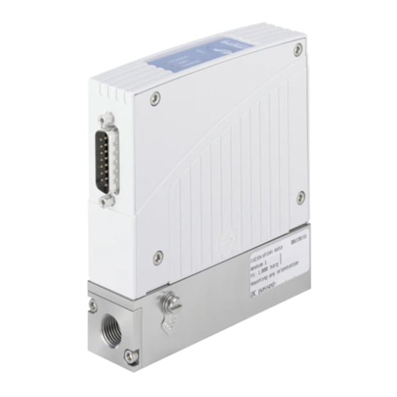
The MFM integrates a sensor for measuring the flow-rate. The measured value for the mass flow-rate is transmitted to a remote Sub-D 15-pin base device via an analogue or a digital output (field bus). Set-point input / Measured flow-rate output / 5.1.2 General operation of the Mass Flow Binary inputs / Controller (MFC) RS232 supply The MFC comprises: • a sensor for measuring the mass flow-rate, 5-pin round base • control electronics, 24 V supply / • a n actuating element: low-friction solenoid control valve with a Relay outputs high response sensitivity. Connection to the line Screw for earth connection Fig. 1: Construction of the MFM / MFC (example of a 8700 / 8701 / 8710 / 8711 with 5-pin round base) english... -
Page 10: Operation Of An Mfm Or Mfc Sensor
Type 8700, 8701, 8703, 8705 Description of the device Operation of an MFM or MFC Detailed operation of an MFC sensor • The integrated flow-rate sensors use the thermal measurement process (anemometric and calorimetric) to measure the mass flow-rate. The main components are a heating resistor and a temperature probe. The gas which passes through the device modifies the temperature difference measured between both = w-x resistors. • The thermal measurement principle allows the MFC to control Control the required mass flow-rate completely independently of electronics inlet outlet the pressure and temperature fluctuations in the application concerned. Actuating element... - Page 11 Type 8710, 8711, 8713, 8715 Description of the device 5.4.1 Control electronics Control settings The initial control settings are set at the factory. The control electronics: • Amplification factors: • process the mass flow-rate set-point values and measured After start-up, the controller operates with amplification factors values, dependent on the loop properties. When the Autotune function • control the solenoid valve. runs, these are determined automatically. This function enables the Set-point value control settings to be optimized for the system's actual conditions.
-
Page 12: Technical Data
Type 8700, 8701, 8703, 8705 Technical data TECHNICAL DATA Zero point shut-off A zero point shut-off is integrated to ensure the sealing function Standards and directives of the valve. This is activated if the following conditions occur at the same time: The device complies with the relevant EU harmonisation legislation. In addition, the device also complies with the requirements of the Set-point value < 2 % of Measured value < 2 % of laws of the United Kingdom. nominal flow-rate Q nominal flow-rate Q (with The harmonised standards that have been applied for the conformity (with control range 1:50) control range 1:50) assessment procedure are listed in the current version of the EU Declaration of Conformity/UK Declaration of Conformity. If the zero point shut-off is active, the PWM signal is set to 0 % so that the valve is completely closed. Certifications 5.4.2 MFC solenoid valve UL-Certification Some versions of the device are UL-certified. For the use of a UL- The solenoid valve used for an MFC is a direct-acting, normally device, please refer to chapter 6.7 Electrical data. -
Page 13: Operating Conditions
Mechanical data WARNING The device may be mounted in a horizontal or vertical position: see the calibration plate and/or the calibration protocol. Risk of injury from malfunction due to effects of weather! Type Base block material Material of the Port The device is not designed for unrestricted use outdoors. housing connections ▶ Protect the device from direct sunlight. 8700, Stainless steel Polycarbonate G 1/4, NPT 1/4, ▶ Observe the ambient temperature permitted for the device. 8710 1.4305 (PC) or sheet flange ▶ Protect the device from humidity. stainless steel 1.4301... -
Page 14: Fluidic Data
Type 8700, 8701, 8703, 8705 Technical data Fluidic data 6.6.2 Quality of the operating medium For the required measurement and control precision and to meet 6.6.1 Overview of measurement the safety requirements, the gas or gas mixture must meet the specifications following quality criteria according to standard ISO 8573-1 (Com- 8700, 8701, 8703, 8705, pressed Air - Part 1: Contaminants and purity classes): 8710 8711... - Page 15 10 15 20 25 30 35 40 45 50 55 60 65 70 75 80 Q [l /min] 10 11 12 13 14 15 Q [l /min] Fig. 4: Pressure loss diagram (reference air, with a 250 µm inlet mesh filter), types 8701 / 8703 Fig. 3: Pressure loss diagram (reference air, with a 250 µm inlet The diagram shows exemplarily the pressure loss characteristics mesh filter), types 8700 / 8705 when air flowing through. The diagram shows exemplarily the pressure loss characteristics Further it differentiates two designs, first one with ¼ inch connectors when air flowing through. and second one with connections on the bottom of the flowmeter (used for assembly on manifolds). For determining the pressure loss with another gas first calculate the air equivalent of the other gas. For determining the pressure loss with another gas first calculate the air equivalent of the other gas and respect the fluidics needed with the other gas.
-
Page 16: Electrical Data
Type 8700, 8701, 8703, 8705 Technical data Electrical data 6.7.1 Electrical data for types 8703 / 8705 / 8713 / 8715 WARNING! For UL-certified components, only use limited power circuits of "NEC Class 2". Specification Type Power supply 24 V DC ±10 %; residual ripple < 2 % Maximum Power required • 8703 / 8705: 2.5 W • 8713 / 8715: 11.5 W Binary input (configurable) 1, to be connected to DGND for activation Communication interface RS485 full or half duplex, supporting the MODBUS protocol Relay output (configurable) 1, potential-free changer, 30 V, 1 A LEDs (configurable) 3 LEDs, status display for POWER, COMM, ERROR... - Page 17 Type 8710, 8711, 8713, 8715 Technical data 6.7.2 Electrical data for types 8700 / 8701 / 8710 / 8711 WARNING! For UL-certified components, only use limited power circuits of "NEC Class 2". Specification Type Power supply 24 V DC ±10 %; residual ripple < 2 % Maximum Power required • 8700 / 8701: 5 W • 8710 / 8711: 14 W MFC 8710 and 8711 only: • 0/4...20 mA, input impedance max.: 300 Ω, resolution : 5 µA Analogue input (configurable) • 0...5/10 V, input impedance min.: 20 kΩ, resolution: 2.5 mV Binary inputs (configurable) 2, to be connected to DGND for activation Analogue output (configurable) • 0/4...20 mA, max. load: 600 Ω, resolution: 20 µA •...
-
Page 18: Markings
Type 8700, 8701, 8703, 8705 Technical data Markings 1. Type of the device 2. Supply voltage, direct current CAUTION 3. Consumption according to UL 61010-1 [typical consumption Risk of injury from pressure and discharge of fluid. 4. Warning symbol: observe the Operating Instructions deli- Important device-specific technical data is indicated on the vered with the device. name plate and the calibration plate. 5. Ambient temperature ▶ Observe the permitted fluid according to the name plate 6. Sealing material (depending on seal material). 7. Burst pressure ▶ Observe the permitted pressure range on the calibration plate of the device. -
Page 19: Installation And Commissioning
Fig. 6: Description of the calibration plate (example) and vent and drain the pipes. Risk of injury from electric shocks. 6.8.3 Additional marking ▶ Before working on the installation or device, switch off the power and ensure that it cannot be reactivated. 1. Conformity ▶ Observe the applicable accident protection and safety regu- marking lations for electrical equipment! 0085 2. Certification Danger due to escape of the medium. ▶ Observe the applicable accident protection and safety regu- lations relating to the operating medium used. E238179 Fig. 7: Description of the additional marking (example) Find the description of the older markings on the device in the supplement at country.burkert.com. english... -
Page 20: Prior To Installation
Type 8700, 8701, 8703, 8705 Installation and commissioning Sequence of the steps to be WARNING performed Danger due to nonconforming installation or commissioning. 1. Mechanical installation ▶ Installation and commisioning can only be carried out by 2. Fluid installation qualified and skilled staff with the appropriate tools. 3. Electrical installation Risk of injury due to unintentional switch on of power supply or uncontrolled restarting of the installation. - Page 21 Type 8710, 8711, 8713, 8715 Installation and commissioning 7.4.2 Setting the bus address on a device with Unit Digit times rotary switches for setting the address Unit position (type 8700 / 8701 / 8710 / 8711) position 0...9 0...9 (x 1) To set an address via the master bus: Decade Digit times → Set the switches on an address outside the permitted position Decade range.
- Page 22 Type 8700, 8701, 8703, 8705 Installation and commissioning 7.4.3 Pin assignment MFM types 8700, 8701: Assignment MFM Typ 8700, 8701 Assignment MFC Typ 8710, 8711 15-pin Sub-D plug Relay - Normally closed contact Relay - Normally open contact Relay - Center contact GND for 24 V - Supply and binary inputs 24 V - Supply + 8 V - Output (for internal use only) Not used Set-point value input GND Not used Set-point value input + Measured value output GND Measured value output +...
- Page 23 Type 8710, 8711, 8713, 8715 Installation and commissioning Pin assignment for field bus version MFM types 8703, 8705 Assignment and MFC types 8713, 8715: PROFIBUS DP socket, Assignment 9-pin Sub-D plug B encoded M12 (DP V1 Binary input max. 12 MBaud) VDD 24 V - Supply + RxD / TxD - N (line A) Relay - C Contact DGND...
-
Page 24: Mechanical Installation
Type 8700, 8701, 8703, 8705 Installation and commissioning Mechanical installation Install the fittings without subjecting them to any stresses. To seal the system properly, use fittings with olives. Observe the mounting position shown on the calibration plate or Use a line with a suitable diameter and a smooth surface. the calibration protocol. → Cut the line squarely [1] and deburr [2]. Fluid installation DANGER Danger due to high pressure in the installation/device. ▶ Before working on the installation or device, cut the pressure and vent and drain the pipes. Select the fluid connections suitable for the maximum flow-rate. There is no minimum upstream distance to be observed. On request, the device may be supplied with the fluid connections → In order, fit the nut [A] and the olive onto the line. fitted. WARNING Klemmring Danger from leaks... - Page 25 Type 8710, 8711, 8713, 8715 Installation and commissioning → Fit the washer [C] and screw the fitting [B] to the device. → Finish tightening the nut with a suitable wrench to ensure the mounting is sealed. → Insert the line and manually tighten the nut [A]. english...
-
Page 26: Electrical Installation
Type 8700, 8701, 8703, 8705 Installation and commissioning Electrical installation NOTE Important information for problem-free functioning of the device DANGER The GND or earth connections of the MFM / MFC must always be connected individually. Risk of injury from electric shocks. If all the GND connections are connected together and only ▶ Before working on the installation or device, switch off the a single common connection fed to the control, the analogue power and ensure that it cannot be reactivated. signals risk being subjected to fluctuations and interference. ▶ Observe the applicable accident protection and safety regu- lations for electrical equipment! → Connect the functional earth (FE) to the screw indicated, for example using an earth terminal. The connection cable must... -
Page 27: Operation And Function
Type 8710, 8711, 8713, 8715 Operation and function OPERATION AND FUNCTION Operation of the MFM / MFC The MFM / MFC is operated by means of analogue standard signals Safety instructions or field bus communication as well as binary inputs. Three LEDs and a relay output are used for operation and status displays. There is a serial interface via which a connection to a PC can be WARNING established, using the "Mass Flow Communicator" software. Risk of injury due to non-conforming operating. Non-conforming operating could lead to injuries and damage Binary inputs / the device and its surroundings. Relay POWER ▶ Operating personnel must familiarize themselves with the output COMM / LIMIT contents of the Operating Instructions. - Page 28 Type 8700, 8701, 8703, 8705 Operation and function 8.2.1 LED default assignment LED status Possible cause LED status Possible cause LIMIT LED (blue) on • MFM: indicates that the measured value has almost POWER LED (green) on The device is energized. reached the nominal flow-rate. POWER LIMIT POWER • MFC: indicates that the ERROR actuating variable of the LIMIT proportional valve has almost ERROR reached 100 %. In practice POWER LED (green) flashing The Autotune function is in...
- Page 29 If the binary inputs are activated, different operations can be run Analogue input/output on the MFC and the latter can be switched to a specific operating The analogue input (MFC only) allows the set-point value, i.e. the mode. This is achieved by connecting the binary input to DGND required flow-rate value in the line, to be received. for at least 0.5 s. The analogue output enables the measured flow-rate value to be supplied to the device to which it is connected. Activation binary input 1 Bus connection (field bus version only) The set-point value received and the measured value are sent digi- tally via the field bus. It is possible to choose between PROFIBUS DP and CANopen (see also the additional Operating Instructions Fig. 9: Types 8703, 8705, 8713 and 8715 for field bus devices). Activation Activation binary input 1 binary input 2 Fig. 10: Types 8700, 8701, 8710 and 8711 Input Default assignment Binary input 1 Autotune actuation Binary input 2 Not used Tab. 1: Default assignment of binary inputs. english...
- Page 30 Type 8700, 8701, 8703, 8705 Operation and function 8.2.3 Relay outputs Function Description Actuate Autotune Start of Autotune function for optimization The MFM / MFC have a relay output to indicate the operating state, of the control settings to the conditions limit values outside the maximum / minimum or a fault. available in the system (see chapter 8.3). Output Assignement Switch to specifi- The calibration curve saved under Gas 2 as Relay output y2 Limit cation 2 well as all settings entered there are used. Totalizer Reset The integrated totalizer (quantity integrator) Tab. 3: Relay output default assignment is reset. Function Description Start set-point Start of the saved set-point value profile Not used No function is assigned to the relay output value profile (see chapter 8.3).
- Page 31 Type 8710, 8711, 8713, 8715 Operation and function Function Description Function Description Close valve com- The close valve completely function is x Limit The measured value has exceeded or pletely active activated. dropped below a limit value which can be configured. Open valve com- The open valve completely function is pletely active activated. w Limit The set-point value has exceeded or dropped below a limit value which can be Defective power The power requirement of the device is configured. requirement monitored. If this value is outside defined limits, this function is actuated. An exces- y2 Limit The actuating variable has exceeded or sively high or low power requirement may dropped below a limit value which can be indicate a defective device. configured. Defective internal The operating voltage of the device is Totalisator Limit The totalizer has exceeded or dropped...
-
Page 32: Mfc Operating Modes
Type 8700, 8701, 8703, 8705 Operation and function MFC operating modes The MFC can adopt different operating modes: Operating mode Status of the LEDs Binary input activation mode This operating mode may be inter- (default setting) rupted or ended by Standard control mode POWER LED (green) on • Autotune function (see chapter 8.3.1) • Safety function POWER •... - Page 33 Type 8710, 8711, 8713, 8715 Operation and function Operating mode Status of the LEDs Binary input activation mode This operating mode may be inter- (default setting) rupted or ended by Set-point value profile LIMIT LED (blue) flashing Input active for at least 0.5 s (per- • Function Autotune (see chapter 8.3.4) manent input activation leads to a • Safety function function restart) POWER •...
- Page 34 Type 8700, 8701, 8703, 8705 Operation and function 8.3.2 Autotune function For the MFC: If the LIMIT LED (blue) is on, this means that the control The Autotune function is run through during the final signal of the proportional solenoid valve is approaching the 100 % limit (see chapter 9.3). inspection in the factory, at the operating pressure and with the calibration fluid indicated in the calibration The cause may be: protocol. • either an insufficient pressure difference around the Therefore, the re-actuation of this function is not MFC, for example an insufficient inlet pressure, essential. • or a dirty inlet filter. However, the Autotune function should be activated if: This means that the set point cannot be achieved and a • the pressure conditions in the system have changed difference between the set point and the measured value significantly, (w - x) persists. • the calibration fluid does not correspond with the operating fluid. For the MFM:...
- Page 35 Type 8710, 8711, 8713, 8715 Operation and function 8.3.4 Set-point value profile WARNING In this operating mode, the device behaves as in standard control Various flow-rate changes occur when the Autotune is run. mode, except that the external set-point value is ignored and ▶ Do not switch off the power supply to the MFC. replaced by a predefined chronology of up to 30 flow-rate values ▶ Keep the supply pressure constant. (configurable with the "Mass Flow Communicator" PC software). This function of the MFC is obtained by activating a binary input → Before activating the Autotune function, bring the medium (configured on this function) for at least 0.5 s. The LIMIT LED (blue) pressure to a pressure close to the calibration pressure. flashes to signal that the function is in progress. While the Autotune function is running, the MFC is not controlling. If the set-point value profile has been activated by binary input When the Autotune function ends, the MFC returns to the operating and the input has been reset, once the set-point value profile has mode it was in prior to activation.
-
Page 36: Maintenance, Troubleshooting
Type 8700, 8701, 8703, 8705 Maintenance, Troubleshooting MAINTENANCE, Maintenance TROUBLESHOOTING The MFM / MFC does not required any maintenance if used as indicated in these Operating Instructions. Routine recalibration is not required. Safety instructions CAUTION DANGER Risk of injury from operating faults and device failure if the Danger due to high pressure in the installation/device. - Page 37 Type 8710, 8711, 8713, 8715 Maintenance, Troubleshooting Procedure (spare parts, see chapter 10.2): 1. Screws → To gain access to the stainless steel mesh filter disc [5], 2. Inlet flange plate detach the input flange plate [2] (see Fig. 11). 3. O-Ring → Take out the stainless steel mesh filter disc [5]. 4. O-Ring → Clean the stainless steel mesh filter disc [5] using distilled 5. Stainless steel mesh water (not tap water), acetone, isopropanol or compressed filter air. 6. Orifice tube → Dry the parts after cleaning. 7. O-Ring → Re-insert parts in the correct sequence and position (see Fig. 11). The fine mesh of the filter disc [5] must face the input flange plate [2].
-
Page 38: If You Encounter Problems
Type 8700, 8701, 8703, 8705 Maintenance, Troubleshooting If you encounter problems Problem Possible cause Recommended action → Check the electrical connections. The POWER LED is off No power supply. The POWER LED flashes The Autotune function is in progress. → See chapter 8.3. POWER COMM ERROR The POWER LED goes The Power supply cuts out periodically; the device → Use a power supply with adequate power. out periodically implements a reset. The voltage drop in the connection cable is too high. → Increase the cable cross section. → Reduce the cable length. The LIMIT LED comes on MFC: the solenoid valve adjustment has almost →... - Page 39 Type 8710, 8711, 8713, 8715 Maintenance, Troubleshooting Problem Possible cause Recommended action → See chapter 8.3. The LIMIT LED is The device is in an operating state other than flashing standard control mode or the Autotune function. POWER LIMIT ERROR The ERROR LED is on Minor fault, for example the last Autotune function → Repeat Autotune has failed. function or reset the device to acknowledge the fault. POWER LIMIT ERROR → Use a power supply with a smooth output The ERROR LED flashes The residual ripple of the supply voltage is too high. voltage at the required power. A serious fault has occurred, e.g.: defective sensor or → Return the device to the manufacturer to have POWER fault in the internal power supply.
- Page 40 Type 8700, 8701, 8703, 8705 Maintenance, Troubleshooting Problem Possible cause Recommended action → Connect the FE to the earthing point (cable as The measured value The earth connection (FE = Functionnal Earth) is not fluctuates correct. short as possible, wire at least 2.5 mm²). The controller must continuously correct fluctuations → Connect a suitable pressure controller upstream. in an unstable pressure supply, e.g. by pumping. → Install a buffer tank to absorb pressure fluctuations. → Use a power supply with a smooth output The residual ripple of the supply voltage is too high. voltage at the required power. → Reduce the operating pressure. Set-point value at The operating pressure is above the operating 0 %, but the fluid is pressure maintained by the proportional valve. → Return the device to the manufacturer to have circulating the fault repaired.
-
Page 41: Accessories / Spare Parts
Type 8710, 8711, 8713, 8715 Accessories / Spare parts ACCESSORIES / SPARE PARTS 10.1.1 Electrical accessories Types Item Order code CAUTION 8700, 8701, SUB-D 15-pin plug to be 918 274 8710, 8711 soldered) Risk of injury and/or damage caused by the use of Cover for SUB-D 15-pin 918 408 unsuitable parts. - Page 42 Type 8700, 8701, 8703, 8705 Accessories / Spare parts 10.1.2 Fluid accessories Types Item Order code PROFIBUS GSD sheet Can be down- The MFM / MFC are equipped with a connection plate which uses versions of loaded at a DIN ISO 228/1 thread process connection. types 8700, country.burkert.com A threaded fitting available as an accessory is used to connect 8701, 8710 the device to a line: and 8711 • the connection to the device side has a DIN ISO 228/1 thread, CANopen Straight M12 plug (code A)
-
Page 43: Spare Part
Mass Flow Controller and field bus devices Liquid Flow Controller families supplied by Bürkert. Contamination Declaration 806 075 "Configuration via PROFIBUS with GDS file" 805 923 The software runs on the Windows platform and commu- addendum nicates with the MFM / MFC via a serial interface. 10.2 Spare part This software enables: Item Order code • information specific to the device to be read, Stainless steel mesh filter, mesh size 250 µm, 654 733 • the assignment of binary inputs and outputs to be changed, for 8700, 8701, 8703 • the assignment of LEDs to be changed, Stainless steel mesh filter, mesh size 25 µm, 676 329 for 8710, 8711, 8713 • various functions to be activated, • certain dynamic properties to be modified, • a user specific calibration to be performed, • the firmware to be updated, • ... english... -
Page 44: Shutdown
Type 8700, 8701, 8703, 8705 Shutdown SHUTDOWN 11.2 Dismounting of the MFM / MFC Procedure: 11.1 Safety instructions DANGER Danger due to high pressure in the installation/device. ▶ Before working on the installation or device, cut the pressure and vent and drain the pipes. Risk of injury from electric shocks. ▶ Before working on the installation or device, switch off the power and ensure that it cannot be reactivated. ▶ Observe the applicable accident protection and safety regu- lations for electrical equipment! Danger due to escape of the medium. -
Page 45: Packaging, Storage, Transport
Type 8710, 8711, 8713, 8715 Packaging, Storage, Transport PACKAGING, STORAGE, 12.2 Storage TRANSPORT NOTE 12.1 Packaging, Transport Poor storage can damage the device. ▶ Store the device in a dry place away from dust. NOTE ▶ Storage temperature: –10 °C...+70 °C. Damage due to transport Inadequately protected equipment may be damaged during transport. ▶... - Page 46 Type 8700, 8701, 8703, 8705 Returning the device RETURNING THE DEVICE DISPOSAL OF THE DEVICE Environmentally friendly disposal No work or tests will be carried out on the device until ▶ Follow national regulations regarding disposal there is a valid Contamination Declaration. and the environment. The Contamination Declaration can be downloaded from ▶...
- Page 48 www.burkert.com...
Need help?
Do you have a question about the 8700 and is the answer not in the manual?
Questions and answers