
Related Manuals for Lincoln Impinger Aperion 24


Summary of Contents for Lincoln Impinger Aperion 24
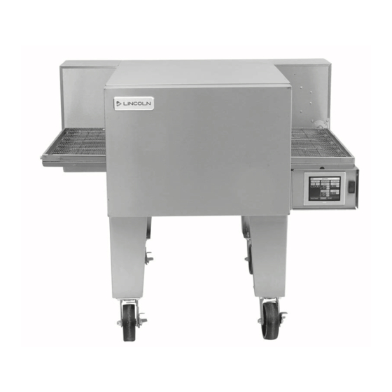
- Page 1 Consistency You Can Count On Lincoln Aperion 24 Impinger® Conveyor Oven Service Manual For 60 HZ Original Document Document #: LIN_EO_SM_IMPAPERION2424_4607818 – 07/21...
-
Page 2: Safety Notices
Safety Notices Warning This appliance is not intended for use by persons DEFINITIONS (including children) with reduced physical, sensory or DANGER mental capabilities, or lack of experience and knowledge, unless they have been given supervision concerning use Indicates a hazardous situation that, if not avoided, will of the appliance by a person responsible for their safety. -
Page 3: Table Of Contents
Table of Contents Safety Notices ........................2 Definitions ........................2 Section 1 General Information Purchaser’s Responsibility ....................6 Additional Requirements ....................6 Section 2 Installation Exterior Dimensions ......................7 Utility Specifications ......................8 Canopy Ventilation Recommendations ................8 Installation Requirements ....................9 Gas Code Requirements .................... - Page 4 Table of Contents (continued) Section 5 Troubleshooting General Issues ......................... 23 UI Alarm Messages ......................27 Section 6 Operation and Programming Introduction ........................29 Startup ..........................29 Recipe Selection (Press& Go Button) ................29 ECO Mode ........................30 Manual Mode ........................ 31 Changing Temperature and Cook Time (Belt Speed) .............31 Settings Mode .......................
- Page 5 Table of Contents (continued) THIS PAGE INTENTIONALLY LEFT BLANK Document #: LIN_EO_SM_IMPAPERION2424_4607818 – 07/21...
-
Page 6: General Information
The requirements of AS 5601 are to be used check-out made by a Factory Authorized Servicer or a Lincoln in conjunction with, but do not take precedence over, any Foodservice Products, LLC Service Representative. -
Page 7: Installation
Section 2 Installation Exterior Dimensions 26.1875" (665 mm) ELECTRIC POWER CONNECTION LOCATION CONVEYOR ASSEMBLY 38.75" 24.8125" (984 mm) (630 mm) 63.5" (1613 mm) 48.4375" (1230 mm) DOOR SWING 26.4375" (672 mm) 48.5625" 37.9375" 10.6875" (1233 mm) 11.6875" (964 mm) (271 mm) (297 mm) 13.1875"... -
Page 8: Utility Specifications
AFF = Above Finished Floor NOTE: The drawing shown is a typical installation and NOTE: Lincoln can provide oven spec sheets that show is intended to be a guideline. Hood dimensions and the the dimensions of the oven, kW or BTU ratings and other... -
Page 9: Installation Requirements
Section 2 Installation Installation Requirements ELECTRICAL CODE REQUIREMENTS Warning DANGER This appliance must be properly grounded at time All utility connections and fixtures must be maintained in of installation. Failure to ensure that this equipment accordance with local and national codes. is properly grounded can result in electrocution, dismemberment or fatal injury. -
Page 10: Spacing Requirements
NOTE: Do not install this (these) oven(s) in any area with an Lincoln “ventless” ovens are not required to be installed ambient temperature in excess of 95°F/35°C. Doing so will under a ventilation hood. For gas ovens, a ventilation hood cause damage to the unit. -
Page 11: Restraint Requirement - Oven(S) On Casters
Section 2 Installation RESTRAINT REQUIREMENT – OVEN(S) ON CASTERS • The installation shall be made with a gas connector that complies with the local codes for Connectors for Movable Gas Appliances, ANSI Z21.69 • CSA 6.16 latest version, and a quick disconnect device that complies with the local codes for Quick Disconnect Devices for Use with Gas Fuel, ANSI Z21.41 •... -
Page 12: Installation
Section 2 Installation The instructions that follow are intended as a guide for preparing for the installation of the Lincoln Aperion Impinger® oven. First and foremost, each crate should be examined before signing the Bill of Lading to report any visible damage by the trucker in transit, and to account for the proper number of crates. -
Page 13: Installation Of 2424 Oven
Section 2 Installation Installation of 2424 Oven Stack Cover Taller 1. Using multiple people, a crane, or forklift remove the With Holes oven from the crate carefully. (Caution) Do not lift from the Left and Right Control Boxes. Left Control Box Right Control Box Leg Kit 4-Places 3. -
Page 14: For Floor Installation
Installation Section 2 For Floor Installation 4. To add a Top Unit to the Stack Assembly. Ensure that the Threaded Pins are installed at the corners of the bottom 1. When placing the Oven on the floor, use the Long Leg of the Top Unit. - Page 15 Section 2 Installation 3. With the Bottom Unit on blocks, connect the Long Leg Kit to the bottom of the Bottom Unit in 4 places. Long Legs Kit 4-Places 5. To add a Top Unit to the Stack Assembly. The Threaded Pins are pre-installed at the corners of the bottom of the Top Unit.
-
Page 16: Start-Up Checkout
Test Procedure: Important NOTE: Use Lincoln Smoke Candle #369361 (in Australia, an The manual shut-off valve must be installed so that the alternate method of coloring the air may be used). test plug is on the oven side of the valve. -
Page 17: Installation Checklist
The warranty shall not apply if the oven is started up and operated prior to the “START-UP CHECKOUT” being Have all gas connections been tested for leaks? performed by a Factory Authorized Servicer or a Lincoln Are the retaining brackets and finger assemblies Foodservice Products, LLC Service Representative. -
Page 18: Sequence Of Operations
Section 3 Sequence of Operations Unit Plugged Into Power 1. Press and Go Selected • UI displays Recipes • Both L1 and L3 10A fuses energized 1.1 Recipe Selected • Safety Contactor Engaged/Energized (If oven high limit capillary and both component hi-limits are •... - Page 19 Section 3 Sequence of Operations THIS PAGE INTENTIONALLY LEFT BLANK Document #: LIN_EO_SM_IMPAPERION2424_4607818 – 07/21...
-
Page 20: Maintenance
1. Clean exterior surfaces of the oven by wiping down However, to achieve the maximum efficiency of the oven, it with Lincoln Oven Cleaner or a mild detergent and clean is necessary to keep it clean. For cleaning instructions, see water, or a commercial stainless cleaner. -
Page 21: Weekly Cleaning
Clean all exterior surfaces of door and pass through window (available option on future models) with Lincoln Oven Cleaner and rinse with clean The Lincoln Aperion Impinger® oven comes with 4 identical finger assemblies comprising a housing and cover and water. -
Page 22: Preventive Maintenance
Maintenance Section 4 3. Remove top 2 housings first, then bottom 2 housings. 5. Re-assemble and re-install in reverse order. Ensure return air baffles are installed between top and bottom finger assemblies. Bottom Finger Assembly 4. Disassemble fingers by sliding cover off the housing. Preventive Maintenance NOTE: Components are tight fitting. -
Page 23: Troubleshooting
Section 5 Troubleshooting General Issues Problem Cause Correction UI blank Oven not plugged in, panel breaker tripped Check panel breaker and plug Ensure input voltage is within specifications Faulty fuses/fuse holder Replace fuses on back panel Replace DC fuse located inside the control box Inspect fuse holders for cracks and replace if needed Wiring Issue Inspect UI cable for damage... - Page 24 Troubleshooting Section 5 Problem Cause Correction Conveyor does not move Temperature set point has not been reached If using the Press & Go menu recipes, wait until UI displays the "Ready" status message Coupling loose or disconnected Tighten set screw on coupling Belt link loose or disconnected Replace belt link Conveyor has stretched from use...
- Page 25 Section 5 Troubleshooting Problem Cause Correction "Unable to reach or maintain "Circuit breaker at the back of the oven tripped Reset circuit breaker at the back of the oven. If temperature" Contactor disengaged " circuit breaker trips again there is an overload on one of the SSR branches or the dual voltage board is malfunctioning (not regulating the heating element current)
- Page 26 Troubleshooting Section 5 Problem Cause Correction “Unable to reach or maintain Defective thermocouple/ thermocouple wiring Verify both thermocouples are connected to the IO temperature” board Inspect the thermocouple wires and connectors. Check wires are not cut or disconnected Check resistance for open probe. Resistance: 7Ω - 14Ω...
-
Page 27: Ui Alarm Messages
Section 5 Troubleshooting UI Alarm Messages UI Alarm Message Cause Correction Motor Drive Status "TC#1 and TC#2 Error" --OR-- "TC#1 One or two thermocouples Verify both thermocouples are Error" --OR-- "TC#2 Error" -- OR -- "Err" disconnected connected to the IO Board in the set point temperature field Inspect the thermocouple wires (manual or recipe mode) - Page 28 Troubleshooting Section 5 UI Alarm Message Cause Correction Motor Drive Status "Upper Blower OV: 0x06" --OR-- "Lower Upper or lower drive overvoltage "Ensure input voltage is within "Red/Yellow Blower OV: 0x06" (line voltage greater than 283VAC) specifications 1 Sec ON/OFF" "...
-
Page 29: Operation And Programming
1. Ensure that your oven is connected to an electrical supply. Move the On/Off switch to the ON position • The display screen will energize and show the Lincoln oven model number and current software version. (Figure 1) This screen will transition after a few seconds to the Home Screen. -
Page 30: Eco Mode
Operation and Programming Section 6 Figure 4 Figure 6 2. The oven is now in pre-heat mode and the oven heaters ECO MODE will start-up. The temperature settings appear on the screen. You will see the temperature of the oven and Eco mode allows the operator to save energy by stopping the the temperature increasing up to the set-point. -
Page 31: Manual Mode
Section 6 Operation and Programming MANUAL MODE Manual mode allows the operator to change the temperature, upper and lower fan speeds, and cook time to revise or create a new recipe. CHANGING TEMPERATURE AND COOK TIME (BELT SPEED) 1. Press the Chef’s Hat or Manual mode button on the Home screen. - Page 32 Operation and Programming Section 6 6. Save Recipe: Press the Save icon in the Manual Mode screen (Figure 16). The screen will transition to a numbered screen (Figure 17). Select the Recipe number and press the check mark. The icon and border color can be changed by selecting the Change Icon and/or Change Color buttons (Figure 18).
-
Page 33: Settings Mode
Section 6 Operation and Programming 3. Temperature Unit of Measure - Touch the white circle in SETTINGS MODE the oval button on the Settings display that shows the Settings mode allows the operator to change the oven temperature measure. The Fahrenheit or Celsius symbol settings such as Temperature unit of measure or Belt will change to correspond to the desired temperature direction. - Page 34 Operation and Programming Section 6 The model setup screen is used to select which Lincoln oven the UI should be configured for. This should be set to “2424” as shown below in (Figure 28). Beside the model selected is the split belt toggle. This should be set to “x2” if the oven is in a split belt configuration.
- Page 35 Section 6 Operation and Programming 9. Conveyor Belt Calibration - From the temperature calibration screen press the “ ” button as highlighted below in (Figure 33). Figure 30 8. Fan Test – From the temperature calibration screen, press the fan test button, highlighted in (Figure 31) below.
-
Page 36: Diagnostics Mode
Operation and Programming Section 6 DIAGNOSTICS MODE Diagnostics mode allows the operator to view basic information about your oven including software revisions and temperature offsets. 1. Press the Diagnostics button on the Home screen to access this mode as shown below in (Figure 37). Figure 34 10. -
Page 37: Oven Shut Down
Section 6 Operation and Programming OVEN SHUT DOWN 1. To shut down your oven, press the Back Button to return to the Home screen. The conveyor should stop moving; however, the cooling fan will continue to run if the oven is hot. - Page 38 Operation and Programming Section 6 THIS PAGE INTENTIONALLY LEFT BLANK Document #: LIN_EO_SM_IMPAPERION2424_4607818 – 07/21...
-
Page 39: Removal, Installation & Adjustments
Section 7 Removal, Installation & Adjustments SOLID STATE RELAY - REPLACEMENT 6. Remove I/O board from the six snap in connectors. 1. Shut off power at main breaker. 7. Reassemble in reverse order. 2. Unplug power cord from power supply. 8. -
Page 40: Cooling Fan - Replacement
Removal, Installation & Adjustments Section 7 COOLING FAN – REPLACEMENT CONTACTOR – REPLACEMENT 1. Shut off power at main breaker. 1. Shut off power at main breaker. 2. Unplug power cord from power supply. 2. Unplug power cord from power supply. 3. -
Page 41: Touchscreen - Replacement
Section 7 Removal, Installation & Adjustments TOUCHSCREEN – REPLACEMENT USB SOCKET – REPLACEMENT 1. Shut off power at main breaker. 1. Shut off power at main breaker. 2. Unplug power cord from power supply. 2. Unplug power cord from power supply. 3. -
Page 42: Cavity Hi-Limit - Replacement
Removal, Installation & Adjustments Section 7 CAVITY HI-LIMIT – REPLACEMENT CONVEYOR BEARINGS – REPLACEMENT 1. Shut off power at main breaker. 1. Remove conveyor assembly from oven cavity and place on flat work surface. 2. Unplug power cord from power supply. 2. -
Page 43: Diagrams
Section 8 Diagrams Wiring Schematics Document #: LIN_EO_SM_IMPAPERION2424_4607818 – 07/21... - Page 44 Notes Document #: LIN_EO_SM_IMPAPERION2424_4607818 – 07/21...
- Page 45 Notes Document #: LIN_EO_SM_IMPAPERION2424_4607818 – 07/21...
- Page 46 Notes Document #: LIN_EO_SM_IMPAPERION2424_4607818 – 07/21...
- Page 47 Section 8 Diagrams THIS PAGE INTENTIONALLY LEFT BLANK Document #: LIN_EO_SM_IMPAPERION2424_4607818 – 07/21...
- Page 48 KitchenCare® aftermarket parts and service. Welbilt’s portfolio of award-winning brands includes Cleveland™, Convotherm®, Crem®, Delfield®, fitkitchen®, Frymaster®, Garland®, Kolpak®, Lincoln®, Manitowoc®, Merco®, Merrychef® and Multiplex®. Bringing innovation to the table • welbilt.com ©2021 Welbilt Inc. except where explicitly stated otherwise. All rights reserved.
Need help?
Do you have a question about the Impinger Aperion 24 and is the answer not in the manual?
Questions and answers