Table of Contents
Advertisement
Quick Links
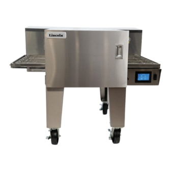
Lincoln Aperion 24 Impinger®
Conveyor Oven
Service Manual
FOR 60 HZ
Models:
1624, 2024, 2424, 2824 series ovens
Original Document
Document #: LIN_EOGO_SM_24APERION_4607818_Rev 1 - 03/24
Consistency You Can Count On
Warning
Post in a prominent location, instructions to be followed
in the event the user smell gas. This information shall be
obtained by consulting your local gas supplier.
FOR YOUR SAFETY
Do not store or use gasoline or other flammable vapors
and liquids in the vicinity of this or any other appliance.
Warning
Improper installation, adjustment, alteration, service
or maintenance can cause property damage, injury, or
death. Read the installation, operating and maintenance
instructions thoroughly before installing or servicing this
equipment.
Read this instruction before operating this equipment.
Caution
Advertisement
Table of Contents

Subscribe to Our Youtube Channel
Related Manuals for Lincoln Aperion 24 Impinger 1624 Series


Summary of Contents for Lincoln Aperion 24 Impinger 1624 Series
- Page 1 Consistency You Can Count On Lincoln Aperion 24 Impinger® Conveyor Oven Service Manual FOR 60 HZ Warning Models: Post in a prominent location, instructions to be followed 1624, 2024, 2424, 2824 series ovens in the event the user smell gas. This information shall be obtained by consulting your local gas supplier.
-
Page 2: Safety Notices
Safety Notices Warning This appliance is not intended for use by persons DEFINITIONS (including children) with reduced physical, sensory or DANGER mental capabilities, or lack of experience and knowledge, unless they have been given supervision concerning use Indicates a hazardous situation that, if not avoided, will of the appliance by a person responsible for their safety. -
Page 3: Table Of Contents
Smoke Candle Test – Ventilation System Verification ............19 Installation Checklist ....................... 19 Checklist ........................20 Section 3 Sequence of Operations 2424 Lincoln Electric Domestic Sequence of operations ....................21 Unit plugged into power ....................21 Power Switch turned ON ....................21 2424 Lincoln Gas Domestic Sequence of operations .................... - Page 4 Table of Contents (continued) Section 4 Maintenance Operator Maintenance ....................23 Cleaning Instructions .....................23 Daily Cleaning ......................... 23 Weekly Cleaning ......................24 Conveyor Removal ......................24 Single Belt Conveyor Tightening ..................24 Split Belt Conveyor Tightening ..................24 Finger Removal ....................... 24 Preventive Maintenance ....................
- Page 5 Temperature Regulating Valve - Replacement ..............54 Burner Blower Motor - Replacement ................54 Burner Transformer - Replacement .................. 54 Section 8 Diagrams Wiring Schematics ......................56 Lincoln 2424 Electric .....................56 Lincoln Aperion 2424/2624 Gas ..................57 Document #: LIN_EOGO_SM_24APERION_4607818_Rev 1 - 03/24...
-
Page 6: Section 1 General Information
The requirements of AS 5601 are to be used check-out made by a Factory Authorized Servicer or a Lincoln in conjunction with, but do not take precedence over, any Foodservice Products, LLC Service Representative. -
Page 7: Stacking Option Dimensions
Section 2 Installation Stacking Option Dimensions TOP VIEW ELECTRICAL GAS CONNECTION CONNECTION TOP VIEW (GAS MODELS) (GAS MODELS) ELECTRICAL CONNECTION (ELECTRIC MODELS) 26.5 1245 49.0 See Page 8 for Model Dimensions and Permitted Stacking Configurations Document #: LIN_EOGO_SM_24APERION_4607818_Rev 1 - 03/24... - Page 8 Installation Section 2 Model Dimensions DIMENSION A- Model Depth B - Conveyor Width C - Leg Spacing, side MODEL inch inch inch 1624 31-3/4 16-3/4 16-9/16 2024 35-3/4 20-3/4 2424 39-3/4 1,010 24-3/4 2824 43-3/4 1,111 28-3/4 Permitted Stacking Configurations Under Exhaust Supporting Surface Single...
-
Page 9: Utility Specifications
Section 2 Installation Utility Specifications Electric Ovens Current Power Recommended Electrical Circuit Breaker Region Phase Configuration Voltage (VAC) Frequency (Hz) (kW) Specification Rating (A) ##24-SU 208 - 240 38.5 - 44.3 13.9 - 18.5 4 Wire, 3 Poles + G 50/60 US/Canada XX24-LU... -
Page 10: Optional Split Belt Conveyor
Installation Section 2 Optional Split Belt Conveyor 2424 2824 Document #: LIN_EOGO_SM_24APERION_4607818_Rev 1 - 03/24... -
Page 11: Gas Unit Connection Locations
Section 2 Installation Gas Unit Connection Locations 2424 GAS DOUBLE STACK SIDE VIEW TOP VIEW 2424 GAS TRIPLE STACK SIDE VIEW NOTE: All 4 SIDE VIEWS APPLY TO BOTH GAS AND ELECTRIC UNITS (WITH THE EXCEPTION OF THE GAS CONNECTION LOCATION DIMENSIONS). -
Page 12: Canopy Ventilation Recommendations
AFF TYP AFF = Above Finished Floor NOTE: The drawing shown is a typical installation and products, Lincoln “ventless” ovens are not required to be is intended to be a guideline. Hood dimensions and the installed under a ventilation hood. -
Page 13: Installation Requirements
Section 2 Installation Installation Requirements ALL OTHER COUNTRIES: Local gas and/or electrical codes will prevail. DANGER 1. Strain Relief is provided with each oven. International Dealer/Distributors provide applicable power cord/plug All utility connections and fixtures must be maintained in for each customer. accordance with local and national codes. -
Page 14: Restraint Requirement Oven S On Casters
Installation Section 2 RESTRAINT REQUIREMENT OVEN S ON CASTERS • The installation shall be made with a gas connector that complies with the local codes for Connectors for Movable Gas Appliances, ANSI Z21.69 • CSA 6.16 latest version, and a quick disconnect device that complies with the local codes for Quick Disconnect Devices for Use with Gas Fuel, ANSI Z21.41 •... -
Page 15: Installation
The instructions that follow are intended as a guide 1. Using multiple people, a crane, or forklift remove the for preparing for the installation of the Lincoln Aperion oven from the crate carefully. (Caution) Do not lift from Impinger® oven. First and foremost, each crate should be the Left and Right Control Boxes. - Page 16 Installation Section 2 4. To add a Top Unit to the Stack Assembly. Ensure that the Threaded Pins are installed at the corners of the bottom Stack Cover Taller of the Top Unit. With Holes Threaded Pin (4x) Leg Kit 4-Places 3.
-
Page 17: For Floor Installation
Section 2 Installation For Floor Installation 3. With the Bottom Unit on blocks, connect the Long Leg Kit to the bottom of the Bottom Unit in 4 places. 1. When placing the Oven on the floor, use the Long Leg Kit with Casters on the Bottom Unit. - Page 18 Installation Section 2 2424 TRIPLE STACK STAND-OFF PLATES (PT# 4608420) 5. To add a Top Unit to the Stack Assembly. The Threaded Pins are pre-installed at the corners of the bottom of the Top Unit. Threaded Pin (4x) 8. Once the units are in place, re-install the Finger Assemblies.
-
Page 19: Start-Up Checkout
“START-UP CHECKOUT” being adequate capture will be the requirement to meet the local performed by a Factory Authorized Servicer or a Lincoln code authority. Foodservice Products, LLC Service Representative. -
Page 20: Checklist
Installation Section 2 CHECKLIST Are the correct clearances maintained? Does the ventilation system meet the requirements? Are the legs and caster securely fastened? Is the unit level? Has the restraint been installed to prevent uncontrolled movement? Have all electrical connections been made and the unit is grounded? Does each oven have a separate disconnect switch? Have all wiring connections including the factory... -
Page 21: Section 3 Sequence Of Operations
Section 3 Sequence of Operations 2424 Lincoln Electric Domestic 1. Press and Go Selected Sequence of operations • UI displays Recipes 1.1 Recipe Selected Unit plugged into power • Unit enters pre-heating mode • 10A fuse F1 energized with L1, and 10A fuse F2 •... -
Page 22: 2424 Lincoln Gas Domestic Sequence Of Operations
Sequence of Operations Section 3 2424 Lincoln Gas Domestic • Ignition Module (IM) energized with L and with 24VAC (if the oven high limit capillary and both Sequence of operations component high limits are not tripped, and if the centrifugal switch closes) Unit plugged into power •... -
Page 23: Section 4 Maintenance
1. Clean exterior surfaces of the oven by wiping down However, to achieve the maximum efficiency of the oven, it with Lincoln Oven Cleaner or a mild detergent and clean is necessary to keep it clean. For cleaning instructions, see water, or a commercial stainless cleaner. -
Page 24: Weekly Cleaning
Clean all exterior surfaces of door and pass through window if applicable with Lincoln Oven Cleaner and rinse with clean water. 6. Remove conveyor, disassemble and clean with Lincoln Oven Cleaner. -
Page 25: Preventive Maintenance
Factory Authorized Servicer to Bottom Finger Assembly establish a proper program. If there are any questions that the service agency cannot answer, please contact the Lincoln 4. Disassemble fingers by sliding cover off the housing. Technical Service Department at 1-844-724-2273. -
Page 26: Section 5 Troubleshooting
Section 5 Troubleshooting General Issues Problem Cause Correction APPLICABLE APPLICABLE FOR GAS UNITS ELECTRIC UNITS User Interface (UI) / Oven not plugged in / panel breaker Check panel breaker and plug touchscreen blank tripped Ensure input voltage is within specifications Fuses / fuse holder Check AC fuses on back panel, replace if necessary... - Page 27 Section 5 Troubleshooting Problem Cause Correction APPLICABLE APPLICABLE FOR GAS UNITS ELECTRIC UNITS Unable to load USB files Faulty flash drive Retry with known good quality flash drive Files on flash drive incorrect or Delete all files on flash drive and reload corrupt updated files Faulty USB socket...
- Page 28 Troubleshooting Section 5 Problem Cause Correction APPLICABLE APPLICABLE FOR GAS UNITS ELECTRIC UNITS Unable to reach or maintain Oven high limit capillary thermostat Turn the power switch OFF and wait temperature tripped for the machine to cooldown (this may No heat take upwards of one hour).
- Page 29 Section 5 Troubleshooting Problem Cause Correction APPLICABLE APPLICABLE FOR GAS UNITS ELECTRIC UNITS Unable to reach or maintain Blower motors not running (no air Check motor drive is powered. Check temperature cont. noise) cont. the motor drive status led codes. Confirm there are no alarm codes Check if motor attempts to move Check wires are connected properly...
- Page 30 Troubleshooting Section 5 Problem Cause Correction APPLICABLE APPLICABLE FOR GAS UNITS ELECTRIC UNITS No low flame present Gas supply Check for adequate gas supply to oven Manual gas shut off valve Check to see that the manual gas shut off valve is open. Also check flexible gas line connection for any damage.
- Page 31 Section 5 Troubleshooting Problem Cause Correction APPLICABLE APPLICABLE FOR GAS UNITS ELECTRIC UNITS No low flame present cont. Transformer Check for 120VAC supplied to the transformer primary. If no voltage is present, trace wiring passing through the centrifugal switch, TH2, TH3 and TH4, until it reaches the SSR.
- Page 32 Troubleshooting Section 5 Problem Cause Correction APPLICABLE APPLICABLE FOR GAS UNITS ELECTRIC UNITS No low flame present cont. Dual Safety Valve cont. When 24VAC is supplied to the valve, the valve should open. Check for gas pressure at the manifold tap located just before the burner.
- Page 33 Section 5 Troubleshooting Problem Cause Correction APPLICABLE APPLICABLE FOR GAS UNITS ELECTRIC UNITS Low flame is ON, but no main/ Temperature Regulation Valve cont. If voltage is present, listen/or feel if high flame present cont. the valve opens and closes. To feel the operation of the valve put an insulated screwdriver on the body of the valve.
-
Page 34: User Interface Alarm Messages
Troubleshooting Section 5 Problem Cause Correction APPLICABLE APPLICABLE FOR GAS UNITS ELECTRIC UNITS No automatic control box Cooling fan thermostat Check the cooling fan thermostat cooling (thermostat closes at 120°F and opens at 100°F). With the cooling fan thermostat preheated, check for continuity. -
Page 35: Alarm Message
Section 5 Troubleshooting USER INTERFACE CAUSE CORRECTION MOTOR APPLICABLE APPLICABLE (TOUCHSCREEN) DRIVE FOR GAS ALARM MESSAGE STATUS LED UNITS ELECTRIC UNITS "Upper Blower OC: 0x03" Upper or lower motor current Check door is closed correctly. Red 0.25 Sec --OR-- overload (drive/motor in Check latches and hinges ON/OFF "Lower Blower OC: 0x03"... - Page 36 Troubleshooting Section 5 USER INTERFACE CAUSE CORRECTION MOTOR APPLICABLE APPLICABLE (TOUCHSCREEN) DRIVE FOR GAS ALARM MESSAGE STATUS LED UNITS ELECTRIC UNITS "Upper Blower Motor Phase Upper or lower motor phase Check motor is connected to Yellow loss (0 RPM)" --OR-- "Lower disconnected drive Blinking...
- Page 37 Section 5 Troubleshooting USER INTERFACE CAUSE CORRECTION MOTOR APPLICABLE APPLICABLE (TOUCHSCREEN) DRIVE FOR GAS ALARM MESSAGE STATUS LED UNITS ELECTRIC UNITS “Thermal Error” cont. High temperature limit tripped Turn the power switch OFF in component compartment and wait for the machine to or cooking cavity, or the circuit cooldown (this may take upwards breaker tripped, resulting in no...
-
Page 38: Section 6 Operation And Programming
1. Ensure that your oven is connected to an electrical supply. Move the On/Off switch to the ON position • The display screen will energize and show the Lincoln oven model number, current software version and serial number (Figure 1). This screen will transition after a few seconds to the Home Screen. -
Page 39: Eco Mode
Section 6 Operation and Programming Figure 6a Figure 4 ECO MODE 2. The oven is now in pre-heat mode (Figure 5) and the Eco mode allows the operator to save energy by stopping oven heaters will start-up. The temperature settings the conveyor belt and reducing fan speed, while maintaining appear on the screen. -
Page 40: Changing Temperature, Cook Time Belt Speed , And Fan Speed
Operation and Programming Section 6 CHANGING TEMPERATURE, COOK TIME BELT SPEED , AND FAN SPEED 1. Press the Chef’s Hat or Manual mode button on the Home screen. (Figure 9 and Figure 10) Figure 12 Figure 9 Figure 13 4. Set Fan Speeds: Press the top fan value to set the upper fan speed. - Page 41 Section 6 Operation and Programming 6. Save Recipe: Press the Save icon in the Manual Mode Screen (Figure 15). You will be asked to enter a password (Figure 16). The password is 4-5-8-7-5-6. The screen will transition to a numbered screen (Figure 17). Select the Recipe you would like to update and press the check mark.
-
Page 42: Settings Mode
Operation and Programming Section 6 4. Belt Direction - Touch the white circle in the oval button SETTINGS MODE on the Settings display that looks like a mini conveyor. Settings mode allows the operator to change the oven The mini conveyor will change to correspond to the settings such as Temperature unit of measure or Belt desired belt direction. - Page 43 “X” to return to the previous setting. Figure 31 The model setup screen is used to select which Lincoln oven the UI should be configured for. This should be set to “2424” as shown below. Beside the model selected is the split belt toggle.
- Page 44 Operation and Programming Section 6 press the fan test button, highlighted in (Figure 35) below. Figure 32 9. Temperature Calibration – From the settings main menu click the temperature calibration button, highlighted Figure 35 below in (Figure 33). The fan test screen sets the upper and lower blower fan speed to 50%.
- Page 45 Section 6 Operation and Programming Measured Time Calibration Value 4:30 0.900 4:35 0.915 4:40 0.935 4:45 0.950 4:50 0.970 4:55 0.985 5:00 1.000 Figure 40 5:05 1.015 13. Gear Ratio – From the conveyor length screen, press 5:10 1.030 the“ ”...
-
Page 46: Diagnostics Mode
Operation and Programming Section 6 DIAGNOSTICS MODE Diagnostics mode allows the operator to view basic information about your oven including software revisions and temperature offsets. 1. Press the Diagnostics button on the Home screen to access this mode. (Figure 24) Figure 46 4. -
Page 47: Oven Shut Down
Section 6 Operation and Programming Oven Shut Down 1. To shut down your oven, press the Back Button to return to the Home screen. The conveyor should stop moving; however, the fans will continue to run if the oven is hot. (Figure 26) Figure 48 2. -
Page 48: Section 7 Removal, Installation & Adjustments
Section 7 Removal, Installation & Adjustments Solid State Relay - Replacement I/O Board – Replacement 1. Shut off power at main breaker. 1. Shut off power at main breaker. 2. Unplug power cord from power supply. 2. Unplug power cord from power supply. 3. -
Page 49: Conveyor Motor Driver - Replacement
Section 7 Removal, Installation & Adjustments Conveyor Motor Driver - Replacement Conveyor Motor Driver - Dip Switches Configuration Shut off power at main breaker and shut off gas: 1. Remove conveyor assembly. The optional stepper controller will have several dip switches on it. -
Page 50: Dual Voltage Control Board - Replacement
Removal, Installation & Adjustments Section 7 Dual Voltage Control Board – Replacement Fan Motor – Replacement 1. Shut off power at main breaker. 1. Shut off power at main breaker. 2. Unplug power cord from power supply. 2. Unplug power cord from power supply. 3. -
Page 51: Conveyor Motor - Replacement
Section 7 Removal, Installation & Adjustments Conveyor Motor – Replacement Fuse Holder - Replacement 1. Shut off power at main breaker. 1. Shut off power at main breaker. 2. Unplug power cord from power supply. 2. Unplug power cord from power supply. 3. -
Page 52: Cooling Fan Thermostat - Replacement
Removal, Installation & Adjustments Section 7 Cooling Fan Thermostat – Replacement Thermocouple – Replacement 1. Shut off power at main breaker. 1. Shut off power at main breaker. 2. Unplug power cord from power supply. 2. Unplug power cord from power supply. 3. -
Page 53: Conveyor Sprocket - Replacement
Section 7 Removal, Installation & Adjustments Conveyor Sprocket – Replacement Gas Valve - Replacement And Adjustment 1. Remove conveyor assembly from oven cavity and place 1. Shut off power at main breaker and shut off gas. on flat work surface. 2. -
Page 54: Temperature Regulating Valve - Replacement
Removal, Installation & Adjustments Section 7 Temperature Regulating Valve - Replacement Burner Blower Motor - Replacement Shut off power at main breaker and shut off gas: Shut off power at main breaker: 1. Remove appropriate control box cover. 1. Shut off power at main breaker. 2. - Page 55 Section 7 Removal, Installation & Adjustments THIS PAGE INTENTIONALLY LEFT BLANK Document #: LIN_EOGO_SM_24APERION_4607818_Rev 1 - 03/24...
-
Page 56: Wiring Schematics
Section 8 Diagrams Wiring Schematics Document #: LIN_EOGO_SM_24APERION_4607818_Rev 1 - 03/24... -
Page 57: Lincoln Aperion 2424/2624 Gas
Section 8 Diagrams Document #: LIN_EOGO_SM_24APERION_4607818_Rev 1 - 03/24... - Page 58 Notes Document #: LIN_EOGO_SM_24APERION_4607818_Rev 1 - 03/24...
- Page 59 Section 8 Diagrams THIS PAGE INTENTIONALLY LEFT BLANK Document #: LIN_EOGO_SM_24APERION_4607818_Rev 1 - 03/24...
- Page 60 LINCOLN FOODSERVICE EQUIPMENT 1200 AIRPORT NORTH OFFICE PARK, SUITE A & B, FORT WAYNE, INDIANA, U.S. 46825 844.724.2273 WWW.LINCOLNFP.COM All rights reserved. Continuing product improvement may necessitate a change of specifications without notice.
Need help?
Do you have a question about the Aperion 24 Impinger 1624 Series and is the answer not in the manual?
Questions and answers