Advertisement
Table of Contents
- 1 Table of Contents
- 2 Section 1: General Information
- 3 Section 2: Operation
- 4 Temperature Calibration
- 5 Conveyor Speed Calibration
- 6 Section 3: Troubleshooting
- 7 Section 4: Component Replacement Procedures
- 8 Section 5: Schematics
- 9 Lincoln Start-Up Form
- 10 Lincoln Equipment Limited Warranty
- Download this manual
Consistency You Can Count On
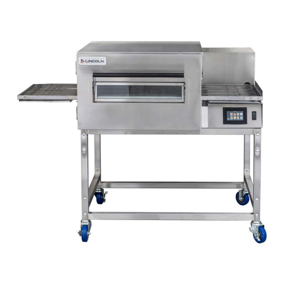
Impinger® II Express
easyTouch & Digital
Series 1100 Series Conveyor Oven
Domestic / International Service Manual
GAS AND ELECTRIC OVENS FOR USA AND NON-USA COUNTRIES
Original Document
Document #: LIN_EOGO_SM_IMPII_S1100_4608349 – 01/22
Advertisement
Table of Contents

Subscribe to Our Youtube Channel
Related Manuals for Lincoln Impinger II 1100 Series


Summary of Contents for Lincoln Impinger II 1100 Series
- Page 1 Consistency You Can Count On Impinger® II Express easyTouch & Digital Series 1100 Series Conveyor Oven Domestic / International Service Manual GAS AND ELECTRIC OVENS FOR USA AND NON-USA COUNTRIES Original Document Document #: LIN_EOGO_SM_IMPII_S1100_4608349 – 01/22...
- Page 2 THIS PAGE INTENTIONALLY LEFT BLANK Document #: LIN_EOGO_SM_IMPII_S1100_4608349 – 01/22...
- Page 3 Safety Notices Warning Authorized Service Representatives are obligated to DEFINITIONS follow industry standard safety procedures, including, DANGER but not limited to, local/national regulations for disconnection / lock out / tag out procedures for all Indicates a hazardous situation that, if not avoided, will utilities including electric, gas, water and steam.
- Page 4 Table of Contents (continued) THIS PAGE INTENTIONALLY LEFT BLANK Document #: LIN_EOGO_SM_IMPII_S1100_4608349 – 01/22...
-
Page 5: Table Of Contents
Section 2: Operation ........................... 9 Temperature Calibration ....................22 Conveyor Speed Calibration ....................22 Section 3: Troubleshooting .......................23 Section 4: Component Replacement Procedures ................61 Section 5: Schematics ........................72 Lincoln Start-Up Form ......................... 92 Lincoln Equipment Limited Warranty ....................94 Document #: LIN_EOGO_SM_IMPII_S1100_4608349 – 01/22... -
Page 6: Section 1: General Information
Section 1 General Information Model Number Key Example: 1133-005-E-K1801 CUSTOM CONFIGURATION CODE (i.e. General Market) LANGUAGE CODE OVEN PLATFORM SIZE 11 33 – – – K1801 (i.e. Impinger III) PANEL SETUP CODE INDICATES CHANGE TO BASE ASSEMBLY (i.e. Natural Gas, 230V, 1 phase, 50 Hz) AGENCY CODE Language Code Agency Code... - Page 7 Section 1 General Information 1100 Series Model Number Old Model Current Model Input Rate Voltage Current Phase #, Supply Wires 1116-080-A 1116-062-A " 1116-xxx-U 3, 1 Pole+N+G 1116-023-A 1116-080-A1 1116-037-U 3, 1 Pole+N+G " 1154-000-EA 1154-xxx-E 3, 2 Pole+G " 1154-080-EA 40,000 BTU/Hr.
- Page 8 4. Arrange for inspection and operation check-out by an Authorized Service Technician. Do not attempt to operate the oven until connection of utility service has been fully inspected by a Factory Authorized Servicer or a Lincoln Foodservice Products, LLC Service Representative. This service is required by LincolnFoodservice Products, LLC in order to assist the purchaser in proper start-up of the oven on site.
-
Page 9: Section 2: Operation
Section 2 Operation Sequence of Operation – Impinger II Domestic Advantage Digital, Gas S/N: 2038616 to S/N: 2106100101444 (Ovens with push button controls) Old Model Number " New Model Number Gas Type Voltages Phase 1116-080-A (or A1) 1116-062-8A " 1116-xxx-U Natural 1116-023-A 120 VAC... - Page 10 Operation Section 2 Sequence of Operation – Impinger II Domestic 1116,1117 easyTouch, Gas S/N: 2106100101445 and above (easyTouch controls) Unit Plugged Into Power • UI displays Recipes • F1 fuse energized with L1 • Recipe Selected • Main Rocker Power Switch Input Energized with L1 and •...
- Page 11 Section 2 Operation Sequence of Operation – Impinger II International Advantage Digital, Gas (Ovens with push button controls) S/N: 21111001007 and Below Old Model Number New Model Number Gas Type Voltages Phase " 1154-000-EA 1154-xxx-E 230VAC 50 Hz " Natural 1154-080-EA 1154-V80-EA "...
- Page 12 Operation Section 2 Sequence of Operation – Impinger II International 1154,1155 easyTouch Gas S/N: 2111100101008 and above (easyTouch controls) Unit Plugged Into Power Press and Go Selected • F1 fuse energized with L1 • UI displays Recipes • Main Rocker Power Switch Input Energized with L1 and •...
- Page 13 Section 2 Operation Sequence of Operation – Impinger II International (Korea) 1157,1158 easyTouch, Gas S/N: 2111100101008 and above (easyTouch controls) Unit Plugged Into Power • UI initiates with Welbilt BOOT screen • Power Failure Alarm Relay common terminals energized • UI Loads to Home Screen after small delay in time with L1 •...
- Page 14 Operation Section 2 Sequence of Operation – Impinger II Domestic Advantage Digital, Electric w/ Neutral S/N 0809210000016 & Below (Ovens with push button controls) Old Model Number " New Model Number Voltages Phase 1130-080-A " 1130-xxx-U 1130-080-A1 120/208 1130-08H-A 1131-080-A "...
- Page 15 Section 2 Operation Sequence of Operation – Impinger II Domestic Advantage Digital, Electric w/o Neutral S/N 0809210000017 to S/N 2104100102812 (Ovens with push button controls) Old Model Number " New Model Number Voltages Phase 1130-080-A " 1130-xxx-U or (V) 1130-080-A1 1130-08H-A 1131-080-A "...
- Page 16 Operation Section 2 Sequence of Operation – Impinger II Domestic 1130,1131 easyTouch, Electric 1 Phase S/N: 2104100102813 and above (easyTouch controls) Unit Plugged Into Power Press and Go Selected • F1 fuse energized with L1 • UI displays Recipes • F2 fuse energized with L2 •...
- Page 17 Section 2 Operation Sequence of Operation – Impinger II Domestic 1132, 1133 easyTouch, Electric 3 Phase S/N: 2104100102813 and above (easyTouch controls) Unit Plugged Into Power • UI displays Recipes • F1 fuse energized with L1 • Recipe Selected • F2 fuse energized with L2 •...
- Page 18 Operation Section 2 Sequence of Operation – Impinger II Domestic Advantage Digital, Electric (Ovens with push button controls) Old Model Number " New Model Number Gas Type Voltage Phase 1135-xxx-U 60 Hz " POWER SUPPLY Electrical power to be supplied to the oven by a three conductor service for single phase and a four conductor service for three phase.
- Page 19 Section 2 Operation Sequence of Operation – Impinger II Domestic Advantage Digital, Electric (Ovens with push button controls) Old Model Number " New Model Number Voltage Phase 1164-000-EA " 1164-xxx-E or (V) 400/230 1164-080-EA POWER SUPPLY Electrical power to be supplied to the oven by a four-conductor service. Brown conductor is hot.
- Page 20 Operation Section 2 Sequence of Operation – Impinger II International 1164 easyTouch, Electric 3 Phase S/N: 2104100102813 and above (easyTouch controls) Unit Plugged Into Power Press and Go Selected • F1 fuse energized with L1 • UI displays Recipes • Safety Contactor input energized with L1, L2, and L3 •...
- Page 21 Section 2 Operation Sequence of Operation – Impinger II International Advantage Digital, Electric (Ovens with push button controls) Old Model Number " New Model Number Gas Type Voltage Phase 1134-xxx-N 380/208 50 Hz " POWER SUPPLY Electrical power to be supplied to the oven by a four-conductor service. Brown conductor is hot.
-
Page 22: Temperature Calibration
Operation Section 2 Temperature Calibration: 1. Place your temperature meter probe directly on the conveyor belt centered in the oven cavity front to back and left to right. 2. Turn oven ON; set oven temperature to 500 F (260 C). Allow 30 minutes preheat for temperatures to stabilize in oven cavity. -
Page 23: Section 3: Troubleshooting
Section 3 Troubleshooting Troubleshooting Guide – Gas Ovens S/N: 2038616 to S/N: 2106100101444 (Ovens with push button controls) Old Model Number " New Model Number Gas Type Voltage Phase 1116-080-A (or A1) " 1116-062-AR 1116-xxx-U Natural 120 VAC 60 Hz "... - Page 24 Troubleshooting Section 3 Problem Cause Correction Oven will not heat, ctd. Hi-limit thermostat, oven cavity Terminals are normally closed. If open, reset thermostat and retest. If thermostat will not hold for maximum oven temperature, and oven is not exceeding temperature setting, check for proper location of capillary bulb in its spring holder.
- Page 25 Section 3 Troubleshooting Problem Cause Correction Low flame is on, but Control transformer Check for 120VAC supply to the primary of the control transformer. If no no main flame voltage is present, trace wiring back to the main power switch. If voltage is present, check for 24VAC at the transformer secondary.
- Page 26 Troubleshooting Section 3 Problem Cause Correction Conveyor(s) will not Conveyor motor Check for 120 VAC supply to the conveyor motor at wire #10 to neutral. run, ctd. If no voltage is present, trace wiring back to the primary of the control transformer.
- Page 27 Section 3 Troubleshooting Troubleshooting Guide – Impinger II Domestic 1116,1117 easyTouch, Gas S/N: 2106100101445 and above (easyTouch controls) Problem Cause Correction UI blank Oven not plugged in, panel breaker Check panel breaker and plug Ensure input voltage is within specifications tripped Faulty fuses/fuse holder Replace fuses on back panel...
- Page 28 Troubleshooting Section 3 Problem Cause Correction Oven fan will not run Incoming power supply Check circuit breakers, reset if required. Check power plug to be sure it is firmly in receptacle. Measure incoming power, call power co. if needed. Fuse, 10 Amp and/or Fuse Holder Check, replace if necessary.
- Page 29 Section 3 Troubleshooting Problem Cause Correction Conveyor does not Temperature set point has not been If using the Press & Go menu recipes, wait until UI move reached displays the “Ready” status message Coupling loose or disconnected Tighten set screw on coupling Belt link loose or disconnected Tighten belt, if needed replace belt link Conveyor has stretched from use...
- Page 30 Troubleshooting Section 3 Problem Cause Correction Unable to reach or Gas supply Check for adequate gas supply to oven. (Natural Gas = 3.5” WC) maintain temperature (LP Gas = 10” WC ) Manual gas shut off valve Check to see that the manual gas shut off valve is open. Also check flexible gas line connection for any damage.
- Page 31 Section 3 Troubleshooting Problem Cause Correction Flame will not stay lit Hot surface igniter Six seconds after the gas valve opens, ignition must occur. If flame is not detected, the ignition control will shut off and lock out. To reset the ignition control, turn off the power switch for 45 seconds, then turn the switch on to re-try ignition.
- Page 32 Troubleshooting Section 3 Problem Cause Correction Low flame is on, but PSU1 (D.C. Power Supply) Check for 120VAC supply to the primary of the no main PSU1. If no voltage is present, trace wiring back to the main power switch. flame If voltage is present, check for 24VDC at the PSU1 secondary.
- Page 33 Section 3 Troubleshooting Troubleshooting Guide – Gas Ovens (Ovens with push button controls) Old Model Number " New Model Number Gas Type Voltage Phase 1154-000-EA " 1154-xxx-E 230 VAC 50 Hz 1154-080-EA Natural " 1154-V80-EA 1157-xxx-N 220 VAC 60 Hz "...
- Page 34 Troubleshooting Section 3 Problem Cause Correction Oven will not heat Gas supply Check for adequate gas supply and be sure that the manual gas shut Main fan off valve is open. Also check flexible gas line connection. Air pressure switch If not operating, refer to “Oven fan will not run”.
- Page 35 Section 3 Troubleshooting Problem Cause Correction NOTE: Flame should be on at this time Low flame is on, but Control transformer Check for supply voltage to the primary of control transformer. If no voltage no main flame is present, trace wiring back to oven EMI filter. If voltage is present, check for voltage at the EMI filter.
- Page 36 Troubleshooting Section 3 Troubleshooting Guide – Impinger II International 1154,1155,1157,1158 easyTouch, Gas S/N: 2106100101445 and above (easyTouch controls) Problem Cause Correction UI blank Oven not plugged in, panel breaker Check panel breaker and plug tripped Ensure input voltage is within specifications Faulty fuses/fuse holder Replace fuses on back panel Inspect fuse holders for cracks and replace if needed...
- Page 37 Section 3 Troubleshooting Problem Cause Correction Oven fan will not run Incoming power supply Check circuit breakers, reset if required. Check power plug to be sure it is firmly in receptacle. Measure incoming power, call power co. if needed. Fuse, 10 Amp and/or Fuse Holder Check, replace if necessary.
- Page 38 Troubleshooting Section 3 Problem Cause Correction Unable to reach or Gas supply Check for adequate gas supply to oven. (Natural Gas = 3.5” WC) maintain temperature (LP Gas = 10” WC ) Manual gas shut off valve Check to see that the manual gas shut off valve is open. Also check flexible gas line connection for any damage.
- Page 39 Section 3 Troubleshooting Problem Cause Correction Flame will not stay lit Flame sensor To check for flame sensor operation, connect a digital multimeter (capable of measuring DC microamps) between the flame sensor wire and the flame sensor connection on the ignition control. Sensor current is to be 0.9 microamps, minimum.
- Page 40 Troubleshooting Section 3 Problem Cause Correction Low flame is on, but Thermocouple Check to be sure that the thermocouple is securely connected to the oven no main flame (See QR chart on page 66) control. If the thermocouple is connected to the oven control, and the control indicates “PROBE FAIL”, disconnect the thermocouple from the oven control and measure the resistance of the thermocouple.
- Page 41 Section 3 Troubleshooting Troubleshooting Guide – Impinger II Domestic Advantage Digital, Electric S/N 0809210000017 to S/N 2104100102812 (Ovens with push button controls) Old Model Number " New Model Number Voltage Phase 1130-080-A " 1130-xxx-U or (V) 1130-080-A1 1130-08H-A 1131-080-A 1131-xxx-U or (V) "...
- Page 42 Troubleshooting Section 3 Problem Cause Correction Main fan runs after 30 30 Minute time delay 208 or 240VAC at terminal #2 should discontinue approx.30 minutes after minute cool down, ctd. (not available on all models) main power is switched off. If the oven start relay contacts are open, and the voltage continues at terminal #2 of the 30 minute timer, for more than 30 minutes, replace the 30 minute time delay.
- Page 43 Section 3 Troubleshooting Problem Cause Correction Oven will not heat, ctd. Thermocouple Check to be sure that the thermocouple is securely connected to the oven (see QR chart on page 66) control. If the thermocouple is connected to the oven control, and the control indicates “PROBE FAIL”, disconnect the thermocouple from the oven control and measure the resistance of the thermocouple.
- Page 44 Troubleshooting Section 3 Problem Cause Correction Conveyor(s) will not Conveyor motor Check for supply voltage to the conveyor motor. If no voltage is present, run ctd. trace wiring back to the primary of the control transformer. If voltage is present and the motor will not run, check the motor windings for opens or shorts.
- Page 45 Section 3 Troubleshooting Troubleshooting Guide – Impinger II Domestic 1130,1131,1132,1133 easyTouch, Electric S/N: 2104100102813 and above (easyTouch controls) Problem Cause Correction UI blank Oven not plugged in, panel breaker Check panel breaker and plug tripped Ensure input voltage is within specifications Faulty fuses/fuse holder Replace fuses on back panel Inspect fuse holders for cracks and replace if needed...
- Page 46 Troubleshooting Section 3 Problem Cause Correction Oven fan will not run Incoming power supply Check circuit breakers, reset if required. Check power plug to be sure it is firmly in receptacle. Measure incoming power, call power co. if needed. Fuses, 10 Amp, motor, and controls Check, replace if necessary. Hi-limit thermostat, Oven cavity Terminals are normally closed.
- Page 47 Section 3 Troubleshooting Problem Cause Correction Oven will not heat, ctd. Thermocouple/ thermocouple Verify the thermocouple is connected to the IO board Inspect the thermocouple wires and connectors. wiring (see QR chart on page 66) Check wires are not cut or disconnected Check resistance for open probe.
- Page 48 Troubleshooting Section 3 Problem Cause Correction Conveyor does not Temperature set point has not been If using the Press & Go menu recipes, wait until UI displays the “Ready” status move reached message Coupling loose or disconnected Tighten set screw on coupling Belt link loose or disconnected Tighten belt, if needed replace belt link Conveyor has stretched from use...
- Page 49 Section 3 Troubleshooting Troubleshooting Guide – Impinger II Domestic Advantage Digital, Electric 1135 (Ovens with push button controls)) Old Model Number New Model Number Voltage Gas Type Phase " 1135-xxx-U 60 HZ " Problem Cause Correction Oven fan will not run Incoming power supply Check circuit breakers.
- Page 50 Troubleshooting Section 3 Problem Cause Correction Main fan runs after 30 30 Minute time delay 240VAC at terminal #2 should discontinue approx. 30 minutes after main minute cool down, ctd. power is switched off. If the oven start relay contacts are open, and the voltage continues at terminal #2 of the 30 minute timer, for more than 30 minutes, replace the 30 minute time delay.
- Page 51 Section 3 Troubleshooting Problem Cause Correction Oven will not heat, ctd. Thermocouple Check to be sure that the thermocouple is securely connected to the oven (see QR chart on page 66) control. If the thermocouple is connected to the oven control, and the control indicates “PROBE FAIL”, disconnect the thermocouple from the oven control and measure the resistance of the thermocouple.
- Page 52 Troubleshooting Section 3 Problem Cause Correction Conveyor will not run, Conveyor motor Check for supply voltage to the conveyor motor. Ifno voltage is present, ctd. trace wiring back to the primary of the control transformer. If voltage is present and the motor will not run, check the motor windings for opens or shorts.
- Page 53 Section 3 Troubleshooting Troubleshooting Guide – Impinger II Non-Domestic Advantage Digital, Electric (Ovens with push button controls)) Old Model Number New Model Number Voltage Phase " 1164-000-EA 1164-xxx-E or (V) " 1164-080-EA 400/230 50 HZ " 1134-xxx-N 380/208 50 HZ Problem Cause Correction...
- Page 54 Troubleshooting Section 3 Problem Cause Correction Oven will not heat, ctd. Oven control Check for 24VAC supply to oven control. If no voltage is present, trace wiring back to control transformer. Check for supply voltage to oven control. If no voltage is present, trace wiring back to oven fan switch. If voltage is present, check for a read-out on the display.
- Page 55 Section 3 Troubleshooting Problem Cause Correction Conveyor will not run Switch, main fan With power off, check continuity between switch terminals. Replace as Display reads”Belt needed. Control transformer Check for supply voltage to the primary of control transformer. If no voltage Jam, ”...
- Page 56 Troubleshooting Section 3 Troubleshooting Guide – Impinger II International 1164 easyTouch, Electric S/N: 2201100100578 and above (easyTouch controls) Problem Cause Correction UI blank Oven not plugged in, panel breaker Check panel breaker and plug tripped Ensure input voltage is within specifications Faulty fuses/fuse holder Replace fuses on back panel Inspect fuse holders for cracks and replace if needed...
- Page 57 Section 3 Troubleshooting Problem Cause Correction Oven fan will not run Incoming power supply Check breaker, reset if required. Check power plug to be sure it is firmly in receptacle. Measure voltage. Fuses, 10 Amp / fuse holders Check, replace if necessary. Hi-limit thermostat, Oven cavity Terminals are normally closed, opens at 660°F (350°...
- Page 58 Troubleshooting Section 3 Problem Cause Correction Oven fan will not heat, Thermocouple/ thermocouple Verify the thermocouple is connected to the IO board Inspect the thermocouple wires and connectors. ctd. wiring Check wires are not cut or disconnected (see chart on page 66) Check resistance for open probe.
- Page 59 Section 3 Troubleshooting Problem Cause Correction Uneven heating Fingers incorrectly installed Make sure fingers are installed correctly Door not closed or does not close Verify door is closed correctly. Check latches and hinges. Check if there is properly excessive gap between door and cavity Overcooked or Incorrect temperature setting Make sure oven temperature is correct...
- Page 60 Component Replacement Procedures Section 4 THIS PAGE INTENTIONALLY LEFT BLANK Document #: LIN_EOGO_SM_IMPII_S1100_4608349 – 01/22...
-
Page 61: Section 4: Component Replacement Procedures
Section 4 Component Replacement Procedures NOTE: To adjust air pressure switch, remove cover from the Warning switch to expose adjusting screw. To increase sensitivity, Before removing or installing any component in the turn screw counter-clockwise; to decrease sensitivity, turn Impinger Oven, be sure to disconnect all electrical screw clockwise. - Page 62 Component Replacement Procedures Section 4 Reversing Conveyor Direction 4. Remove mounting nut and remove hot surface igniter assembly. Shut off power at oven switch: 5. Reassemble in reverse order and check system 1. Set reversing switch in the other position. operation.
- Page 63 Section 4 Component Replacement Procedures Main Orifice On-Off Switch (Power) REPLACEMENT REPLACEMENT Shut off power at main breaker and shut off gas: Shut off power at main breaker: 1. Remove rear control box cover. 1. Shut off power at main breaker. 2.
- Page 64 Component Replacement Procedures Section 4 Relay Main Fan and Motor REPLACEMENT REPLACEMENT Shut off power at main breaker: Shut off power at main breaker and shut off gas: 1. Remove appropriate control box cover. 1. Shut off gas supply. 2. Remove wires from relay, note wire numbers and 2.
- Page 65 Section 4 Component Replacement Procedures Heating Element Bearing, Conveyor REPLACEMENT REPLACEMENT Shut off power at main breaker: Shut off power at main breaker: 1. Remove back cover. 1. Remove conveyor from oven and place on a flat work surface. 2. Disconnect heating element wires and mark for reassembly.
- Page 66 Component Replacement Procedures Section 4 Thermocouple (Type K) For additional Thermocouple Measurement Scan QR Code: REPLACEMENT Shut off power at main breaker: For standard Finger configurations: 1. Remove rear panel assembly. 2. Remove front control box cover. 3. Remove thermocouple from bracket in oven chamber and pull thermocouple through tube into control box.
- Page 67 Section 4 Component Replacement Procedures Techrite Module (Export Models) REPLACEMENT Shut off power at main breaker and shut off gas: 1. Remove appropriate control box cover. 2. Remove wires from plug-in terminal strip, note wire numbers and location. 3. Remove two (2) screws from mounting bracket and remove.
- Page 68 Component Replacement Procedures Section 4 Techrite Module LED Flash Code (Export Models) The following codes are invoked as a result of a lockout condition. LED Flash Code Description (Long flashes–short flashes) Maximum retries exceeded. Lockout due to flame failure. Hardware failure on module output(s). 2-3, 2-4, 2-5 Possible hardware failure in module.
- Page 69 Section 4 Component Replacement Procedures Power Filter Mercury Contactor REPLACEMENT REPLACEMENT Shut off power at main breaker: Shut off power at main breaker: 1. Remove control box cover. 1. Remove rear control box cover. 2. Remove all wires from the power filter, note all wire 2.
- Page 70 Component Replacement Procedures Section 4 UI Alarm Messages Guide for easyTouch Controller UI Alarm Message Cause Correction "ERR_THERMOCPL" The thermocouple Verify the thermocouples is disconnected connected to the IO Board. Inspect the thermocouple wires and connectors to verify wires are not cut or disconnected.
- Page 71 Section 4 Component Replacement Procedures Conveyor Motor Driver Conveyor Motor Driver REPLACEMENT Dip Switches Configuration Shut off power at main breaker and shut off gas: The optional stepper controller will have several dip 1. Remove conveyor assembly. switches on it. When replacing this controller makes sure the following switches are in the proper sequence.
-
Page 72: Section 5: Schematics
Section 5 Schematics 1116-000-A, 1117-000-A Schematic - S/N 2038616 to S/N 0809210000016 Document #: LIN_EOGO_SM_IMPII_S1100_4608349 – 01/22... - Page 73 Section 5 Schematics 1116, 1117 Schematic - S/N 0809210000017 and Above Document #: LIN_EOGO_SM_IMPII_S1100_4608349 – 01/22...
- Page 74 Schematics Section 5 1116, 1117 Split Belt Schematic - S/N 0809210000017 and Above Document #: LIN_EOGO_SM_IMPII_S1100_4608349 – 01/22...
- Page 75 Section 5 Schematics 1116, 1117 easyTouch Schematic - S/N 2106100101445 and Above Document #: LIN_EOGO_SM_IMPII_S1100_4608349 – 01/22...
- Page 76 Schematics Section 5 1154, 1155, 1157, 1158 Schematic - S/N 1902100102504 and Below Document #: LIN_EOGO_SM_IMPII_S1100_4608349 – 01/22...
- Page 77 Section 5 Schematics 1154, 1155, 1157, 1158 with Techrite Module Schematic - S/N 1902100102505 to S/N 2111100101007 LOAD Document #: LIN_EOGO_SM_IMPII_S1100_4608349 – 01/22...
- Page 78 Schematics Section 5 1154, 1155, 1157, 1158 Split Belt Schematic - S/N 1902100102505 and Below Document #: LIN_EOGO_SM_IMPII_S1100_4608349 – 01/22...
- Page 79 Section 5 Schematics 1154, 1155 easyTouch Schematic - S/N 2111100101008 and Above Document #: LIN_EOGO_SM_IMPII_S1100_4608349 – 01/22...
- Page 80 Schematics Section 5 1157, 1158 easyTouch Schematic -S/N 2111100101008 and Above Document #: LIN_EOGO_SM_IMPII_S1100_4608349 – 01/22...
- Page 81 Section 5 Schematics 1130-080-A, 1130-080-A1, 1131-080-A, 1131-080-A1 S/N: 0809210000015 and Below Schematic Document #: LIN_EOGO_SM_IMPII_S1100_4608349 – 01/22...
- Page 82 Schematics Section 5 1132-080-A, 1132-080-A1, 1133-000-A, 1133-080-A1 S/N: 0809210000015 & and Below Schematic Document #: LIN_EOGO_SM_IMPII_S1100_4608349 – 01/22...
- Page 83 Section 5 Schematics 1130, 1131, 1132, 1133 Schematic - S/N 0809210000017 and Above Document #: LIN_EOGO_SM_IMPII_S1100_4608349 – 01/22...
- Page 84 Schematics Section 5 1132-002 Schematic - S/N 0809210000017 and Above Document #: LIN_EOGO_SM_IMPII_S1100_4608349 – 01/22...
- Page 85 Section 5 Schematics 1130, 1131 easyTouch Schematic - S/N 2104100102813 and Above Document #: LIN_EOGO_SM_IMPII_S1100_4608349 – 01/22...
- Page 86 Schematics Section 5 1132, 1133 easyTouch Schematic - S/N 2104100102813 and Above Document #: LIN_EOGO_SM_IMPII_S1100_4608349 – 01/22...
- Page 87 Section 5 Schematics 1134 Schematic - S/N 2104100102812 and Below Document #: LIN_EOGO_SM_IMPII_S1100_4608349 – 01/22...
- Page 88 Schematics Section 5 1135 Schematic - S/N 2104100102812 and Below Document #: LIN_EOGO_SM_IMPII_S1100_4608349 – 01/22...
- Page 89 Section 5 Schematics 1164 Schematic - S/N 2201100100577 and Below Document #: LIN_EOGO_SM_IMPII_S1100_4608349 – 01/22...
- Page 90 Schematics Section 5 1164 Split Belt Schematic - S/N 2201100100577 and Below Document #: LIN_EOGO_SM_IMPII_S1100_4608349 – 01/22...
- Page 91 Section 5 Schematics 1164 easyTouch Schematic - S/N 2201100100578 and Above Document #: LIN_EOGO_SM_IMPII_S1100_4608349 – 01/22...
-
Page 92: Lincoln Start-Up Form
Does each oven have its own neutral wire which runs all the way back to the circuit breaker panel? _________________________ NOTE: IF INCOMING VOLTAGES ARE NOT CORRECT, DO NOT OPERATE OVEN(S). Is Lincoln gas shut off valve (369081 supplied) installed properly on each oven? ____________ Note: Check for gas leaks with bubble soap, and DO NOT OPPERATE OVEN(S) if a leak can not be tightened. - Page 93 Section 5 Schematics Impinger® II Express easyTouch & Digital Series 1100 Series Conveyor Oven Start up Form Document #: LIN_EOGO_SM_IMPII_S1100_4608349 – 01/22...
-
Page 94: Lincoln Equipment Limited Warranty
• Any breach by Lincoln with respect to any item or unit of equipment EXCLUSIONS FROM COVERAGE or services shall be deemed a breach with respect to that item or unit or service only. - Page 95 Section 5 Schematics THIS PAGE INTENTIONALLY LEFT BLANK Document #: LIN_EOGO_SM_IMPII_S1100_4608349 – 01/22...
- Page 96 KitchenCare® aftermarket parts and service. Welbilt’s portfolio of award-winning brands includes Cleveland™, Convotherm®, Crem®, Delfield®, fitkitchen®, Frymaster®, Garland®, Kolpak®, Lincoln®, Manitowoc®, Merco®, Merrychef® and Multiplex®. Bringing innovation to the table • welbilt.com ©2022 Welbilt Inc. except where explicitly stated otherwise. All rights reserved.
Need help?
Do you have a question about the Impinger II 1100 Series and is the answer not in the manual?
Questions and answers
Останавливается на время конвейер
The Lincoln Impinger II 1100 Series conveyor may stop intermittently due to:
1. Improper ventilation or lack of preventive maintenance.
2. Loose or disconnected coupling or belt link.
3. Stretched conveyor belt requiring link removal.
4. Incorrect belt installation or orientation.
5. Software issue—may require power cycling and manual mode adjustment.
6. Failed or failing stepper motor—check motor resistance.
7. Faulty IO board or motor drive—verify 24VDC input and wiring.
8. Faulty Hall Effect sensor or missing frequency output.
9. Faulty oven control not supplying proper voltage to the Hall Effect sensor.
Each of these should be inspected and corrected as needed.
This answer is automatically generated