Panasonic PT-RZ21К Operating Instructions Manual
Hide thumbs
Also See for PT-RZ21К:
- Operating instructions manual (253 pages) ,
- Command list (26 pages) ,
- Operating instructions manual (254 pages)
Table of Contents
Advertisement
Quick Links
Thank you for purchasing this Panasonic product.
■ The Operating Instructions correspond to the firmware's main version 4.00 and higher.
■ This manual is common to all the models.
z for India
PT-RZ21KD
z for Taiwan
PT-RZ21K
z for other countries or regions
PT-RZ21K / PT-RS20K
■ Before operating this product, please read the instructions carefully and save this manual
for future use.
■ Before using this product, be sure to read "Read this first!" ( x pages 5 to 15).
Operating Instructions
DLP™ Projector
Model No.
The projection lens is sold separately.
Functional Manual
Commercial Use
PT-RZ21K
PT-RS20K
ENGLISH
DPQP1195ZG
Advertisement
Table of Contents

Related Manuals for Panasonic PT-RZ21К


Summary of Contents for Panasonic PT-RZ21К
- Page 1 Model No. PT-RS20K The projection lens is sold separately. Thank you for purchasing this Panasonic product. ■ The Operating Instructions correspond to the firmware’s main version 4.00 and higher. ■ This manual is common to all the models. z for India...
-
Page 2: Table Of Contents
Contents Contents Read this first! Chapter 3 Basic Operations Switching on/off the projector Chapter 1 Preparation Connecting the power cord Power indicator Precautions for use Switching on the projector Cautions when transporting When the initial setting screen is displayed Cautions when installing Making adjustments and selections Cautions when setting up the projector Switching off the projector... - Page 3 Contents [PICTURE] menu [DISPLAY OPTION] menu [PICTURE MODE] [COLOR MATCHING] [CONTRAST] [LARGE SCREEN CORRECTION] [BRIGHTNESS] [SCREEN SETTING] [COLOR] [AUTO SIGNAL] [TINT] [AUTO SETUP] [COLOR TEMPERATURE] [BACKUP INPUT SETTING] [GAMMA] [SIMUL INPUT SETTING] [SYSTEM DAYLIGHT VIEW] [RGB IN] [SHARPNESS] [DVI-D IN] [NOISE REDUCTION] [HDMI IN] [DYNAMIC CONTRAST]...
- Page 4 Contents Chapter 7 Appendix [SIGNAL LIST] menu Registering new signals Technical information Renaming the registered signal PJLink protocol Deleting the registered signal Using Art-Net function Protecting the registered signal Control commands via LAN Expanding signal lock-in range <SERIAL IN>/<SERIAL OUT> terminal Sub memory <REMOTE 2 IN>...
-
Page 5: Read This First
Read this first! Read this first! WARNING: THIS APPARATUS MUST BE EARTHED. WARNING: To prevent damage which may result in fire or shock hazard, do not expose this appliance to rain or moisture. This device is not intended for use in the direct field of view at visual display workplaces. To avoid incommoding reflexions at visual display workplaces this device must not be placed in the direct field of view. - Page 6 Read this first! WARNING: RISK OF ELECTRIC SHOCK. DON’T OPEN Indicated on the projector The lightning flash with arrowhead symbol, within an equilateral triangle, is intended to alert the user to the presence of uninsulated “dangerous voltage” within the product’s enclosure that may be of sufficient magnitude to constitute a risk of electric shock to persons.
- Page 7 Read this first! (for India) This projector is the Class 1 laser product that complies with IEC/EN 60825-1:2014. (for other countries or regions) This projector is the Class 1 laser product that complies with IEC/EN 60825-1:2014. CAUTION: Use of controls or adjustments or performance of procedures other than those specified herein may result in hazardous radiation exposure.
- Page 8 FCC NOTICE (USA) Verification Model Number: PT-RZ21K / PT-RS20K Trade Name: Panasonic Responsible Party: Panasonic Corporation of North America Address: Two Riverfront Plaza, Newark, NJ 07102-5490 General Contact: http://www.panasonic.com/support Projector Contact: https://panasonic.net/cns/projector/ This device complies with Part 15 of the FCC Rules.
- Page 9 L or colored RED. How to replace the fuse: Open the fuse compartment with a screwdriver and replace the fuse. Importer’s name and address within the European Union Panasonic Marketing Europe GmbH Panasonic Testing Centre Winsbergring 15, 22525 Hamburg, Germany...
- Page 10 Read this first! r Hazard distance (IEC 62471-5:2015) The distance from the projection lens surface, at which the level of exposure has reached the level of the applicable Exposure Limit Value, is known as the hazard distance (HD) or safety distance. Do not look into the projected light from inside the hazard distance (within RG3 range).
- Page 11 Read this first! WARNING: r POWER The wall outlet or the circuit breaker shall be installed near the equipment and shall be easily accessible when problems occur. If the following problems occur, cut off the power supply immediately. Continued use of the projector in these conditions will result in fire or electric shock, or will cause visual impairment.
- Page 12 If liquid enters inside of the projector, consult your dealer. f Particular attention must be paid to children. Use the ceiling mount bracket specified by Panasonic. Using the ceiling mount bracket other than the specified one will result in falling accidents.
- Page 13 Read this first! CAUTION: r POWER When disconnecting the power cord, be sure to hold the power plug and power connector. If the power cord itself is pulled, the lead will become damaged, and fire, short-circuits or serious electric shocks will result.
- Page 14 Read this first! CAUTION: r ACCESSORIES When not using the projector for an extended period of time, remove the batteries from the remote control. Failure to observe this will cause the batteries to leak, overheat, catch fire or explode, which may result in fire or contamination of surrounding area.
- Page 15 Read this first! To remove the battery Remote Control Battery 1. Press the guide and lift the cover. 2. Remove the batteries. (ii) Brazil Only Brasil Apenas r Manuseio de baterias usadas BRASIL Após o uso, as pilhas e/ou baterias deverão ser entregues ao estabelecimento comercial ou rede de assistência técnica autorizada.
- Page 16 SOLID SHINE is a trademark of Panasonic Corporation. f Windows and Internet Explorer are registered trademarks or trademarks of Microsoft Corporation in the United States and other countries. f Mac, macOS, and Safari are trademarks of Apple Inc., registered in the United States and other countries.
- Page 17 Features of the Projector Quick Steps For details, refer to the corresponding pages. 1. Set up the projector. High luminance and high contrast (x page 36) ▶ With the high efficient optical system that maximizes the output of the solid- state light source, and unique drive 2.
-
Page 18: Chapter 1 Preparation
Preparation Chapter 1 This chapter describes things you need to know or check before using the projector. 18 - ENGLISH... -
Page 19: Precautions For Use
Chapter 1 Preparation — Precautions for use Precautions for use Cautions when transporting f Transport the projector with two or more people. Failure to do so may drop the projector, which may result in damage or deformation of the projector, or injury. f When transporting the projector, hold it securely by its bottom and avoid excessive vibration and impact. -
Page 20: Cautions When Setting Up The Projector
Chapter 1 Preparation — Precautions for use rDo not use the projector in a location that the ambient temperature exceeds 50 °C (122 °F). Using the projector in a location that the altitude is too high or the ambient temperature is too high may reduce the life of the components or result in malfunctions. - Page 21 Chapter 1 Preparation — Precautions for use f Use a torque screwdriver or Allen torque wrench to tighten the fixing screws to their specified tightening torques. Do not use electric screwdrivers or impact screwdrivers. (Screw diameter: M6, tapping depth inside the projector: 27 mm (1-1/16"), screw tightening torque: 4 ± 0.5 N·m) Unit: mm Adjustable feet Screw holes to fix the projector...
-
Page 22: Security
Panasonic takes no responsibility for any damage to the product caused by an inappropriate choice of location for installing the projector, even if the warranty period of the product has not expired. -
Page 23: Digital Link
Note that the verification for devices of other manufacturers has been made for the items set by Panasonic Corporation, and not all the operations have been verified. For operation or performance problems caused by the devices of other manufacturers, contact the respective manufacturers. This projector does not support audio transmission because it is not equipped with audio function. - Page 24 Chapter 1 Preparation — Precautions for use rDo not touch the surface of the projection lens with your bare hands. If the surface of the projection lens becomes dirty from fingerprints or anything else, this will be magnified and projected onto the screen. Attach the supplied lens cover to the optional projection lens when not using the projector.
-
Page 25: Accessories
Chapter 1 Preparation — Precautions for use Accessories Make sure that the following accessories are provided with your projector. Numbers enclosed in < > show the number of accessories. Wireless/wired remote control unit <1> Lens hole cover <1> (N2QAYB001052 [N2QAYB001176]) (1GE1RZ21K) (Attached to the product at the time of purchase) CD-ROM <1>... - Page 26 Chapter 1 Preparation — Precautions for use Lens hood mounting plate 2 <1> Lens hood screw <6> (DPMH1089ZA) (XYN4+F8FJK) Knurled head screw <6> (DPHD1026ZA) Attention f After unpacking the projector, discard the power cord cap and packaging material properly. f Do not use the supplied power cord for devices other than this projector. f For missing accessories, consult your dealer.
-
Page 27: Optional Accessories
The model numbers of optional accessories are subject to change without prior notice. f The optional accessories described in this document are as of September 2017. Optional accessories may be added or changed without prior notice. For the latest information, visit the Panasonic website (https://panasonic.net/cns/projector/). ENGLISH - 27... -
Page 28: About Your Projector
Chapter 1 Preparation — About your projector About your projector Remote control Front Bottom A strap can be attached depending on the usage. Remote control indicator 12 Input selection buttons (<RGB1>, <RGB2>, <VIDEO>, <S-VIDEO Y/C>, <DIGITAL LINK>, <DVI-D>, <HDMI>, <SDI>) Blinks if any button in the remote control is pressed. Switches the input signal to project. - Page 29 Chapter 1 Preparation — About your projector f Avoid contact with liquids or moisture. f Do not attempt to modify or disassemble the remote control. f Do not swing the remote control holding onto the strap when a strap is attached. f Observe the following instructions that are indicated on the caution label at the back of the remote control: g Do not use old battery with new one.
-
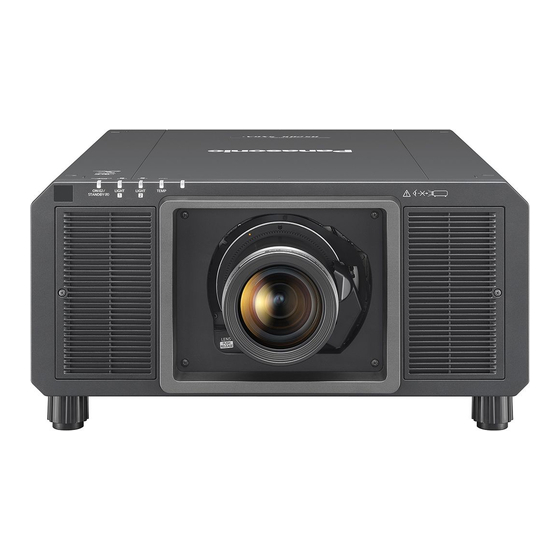
Page 30: Projector Body
Chapter 1 Preparation — About your projector Projector body Front Side 3 4 5 Rear Light source indicator <LIGHT1> Bottom Indicates the status of light source 1. Light source indicator <LIGHT2> Indicates the status of light source 2. Temperature indicator <TEMP> Indicates the internal temperature status. - Page 31 Chapter 1 Preparation — About your projector r Control panel Power on <b> button 11 <MENU> button Sets the projector to projection mode when the <MAIN Displays or hides the main menu. (x page 85) POWER> switch on the projector is set to <ON> and the power Returns to the previous menu when a sub-menu is displayed.
- Page 32 Chapter 1 Preparation — About your projector r Connecting terminals <REMOTE 1 IN> terminal/<REMOTE 1 OUT> terminal <DC OUT 1> terminal/<DC OUT 2> terminal These are terminals to connect the remote control for serial This is the USB terminal dedicated for power supply. (DC 5 V, control in a multiple projector environment.
-
Page 33: Preparing The Remote Control
Chapter 1 Preparation — Preparing the remote control Preparing the remote control Inserting and removing the batteries (ii) Fig. 1 Fig. 2 Open the cover. (Fig. 1) Insert the batteries and close the cover (insert the m side first). (Fig. 2) f When removing the batteries, perform the steps in reverse order. -
Page 34: Connecting The Remote Control To The Projector With A Cable
Chapter 1 Preparation — Preparing the remote control Connecting the remote control to the projector with a cable If you control the multiple projectors with a single remote control, use commercially available M3 stereo mini jack cables to connect to the <REMOTE 1 IN>/<REMOTE 1 OUT> terminals of the projectors. The remote control is effective even in places where an obstacle stands in the light path or where devices are susceptible to outside light. -
Page 35: Chapter 2 Getting Started
Getting Started Chapter 2 This chapter describes things you need to do before using the projector such as the setup and connections. ENGLISH - 35... -
Page 36: Setting Up
Chapter 2 Getting Started — Setting up Setting up Usable outlet This projector supports AC100 V to AC120 V, and AC 200 V to AC 240 V as the power supply. A grounding outlet supporting 15 A is required with either voltage. The shape of the usable outlet differs depending on the power supply. - Page 37 Chapter 2 Getting Started — Setting up Mounting on the ceiling and projecting forward Mounting on the ceiling and projecting from rear (Using the translucent screen) Menu item Setting value Menu item Setting value [FRONT/REAR] [FRONT] [FRONT/REAR] [REAR] [FLOOR/CEILING] [AUTO] or [CEILING] [FLOOR/CEILING] [AUTO] or [CEILING] Portrait setting and projecting forward...
-
Page 38: Parts For Installation (Optional)
Chapter 2 Getting Started — Setting up Parts for installation (optional) The optional Ceiling Mount Bracket is required. The Ceiling Mount Bracket (Model No.: ET-PKD520H (for High Ceilings), ET-PKD520S (for Low Ceilings)) is used together with the Ceiling Mount Bracket (Model No.: ET-PKD520B (Projector Mount Bracket)). - Page 39 Chapter 2 Getting Started — Setting up r Fixed-focus Lens (Model No.: ET-D75LE95, ET-D75LE90) Projected image Screen Screen (Unit: m) Projected image height Projected image width Projected image size Projection distance (from the screen to the mirror reflection surface Distance between the projector and the screen (from the screen to the tip of the lens) Distance between the projector and the screen (from the screen to the front surface of the projector) Distance between the projector and the screen (from the screen to the rear surface of the projector) Distance between the projector and the screen (from the screen bottom edge to the projector top)
- Page 40 Chapter 2 Getting Started — Setting up [GEOMETRY] projection range [VERTICAL KEYSTONE] (viewed from the side) [HORIZONTAL KEYSTONE] (viewed from above) Screen Screen Vertical arc correction (viewed from the side) Horizontal arc correction (viewed from above) Projection distance Projection distance Arc radius Arc radius Screen Screen...
- Page 41 Chapter 2 Getting Started — Setting up Standard status Only [CURVED Only [KEYSTONE] used [KEYSTONE] and [CURVED CORRECTION] used together CORRECTION] used Projection Vertical Horizontal Vertical Horizontal lens Model keystone keystone keystone keystone Min. value of Min. value of Min. value of Min.
- Page 42 Chapter 2 Getting Started — Setting up Projection distance of each projection lens A ±5 % error in listed projection distances may occur. When [GEOMETRY] is used, distance is corrected to become smaller than the specified image size. For PT-RZ21K r When the image aspect ratio is 16:10 (Unit: m) Lens type Zoom Lens...
- Page 43 Chapter 2 Getting Started — Setting up r When the image aspect ratio is 16:9 (Unit: m) Lens type Zoom Lens Projection lens Model No. ET-D75LE6 ET-D75LE10 ET-D75LE20 ET-D75LE30 ET-D75LE40 ET-D75LE8 Throw ratio 0.924-1.10:1 1.30-1.67:1 1.67-2.41:1 2.41-4.66:1 4.62-7.38:1 7.34-13.8:1 Projected image size Projection distance (L) Height Min.
- Page 44 Chapter 2 Getting Started — Setting up r When the image aspect ratio is 4:3 (Unit: m) Lens type Zoom Lens Projection lens Model No. ET-D75LE6 ET-D75LE10 ET-D75LE20 ET-D75LE30 ET-D75LE40 ET-D75LE8 Throw ratio 1.12-1.32:1 1.56-2.01:1 2.00-2.90:1 2.89-5.60:1 5.55-8.86:1 8.82-16.6:1 Projected image size Projection distance (L) Height Min.
- Page 45 Chapter 2 Getting Started — Setting up For PT-RS20K r When the image aspect ratio is 4:3 (Unit: m) Lens type Zoom Lens Projection lens Model No. ET-D75LE6 ET-D75LE10 ET-D75LE20 ET-D75LE30 ET-D75LE40 ET-D75LE8 Throw ratio 1.01-1.19:1 1.41-1.81:1 1.80-2.61:1 2.60-5.05:1 5.00-7.99:1 7.95-14.9:1 Projected image size Projection distance (L) Height...
- Page 46 Chapter 2 Getting Started — Setting up r When the image aspect ratio is 16:9 (Unit: m) Lens type Zoom Lens Projection lens Model No. ET-D75LE6 ET-D75LE10 ET-D75LE20 ET-D75LE30 ET-D75LE40 ET-D75LE8 Throw ratio 1.01-1.19:1 1.41-1.81:1 1.81-2.61:1 2.61-5.05:1 5.00-7.99:1 7.96-15.0:1 Projected image size Projection distance (L) Height Min.
- Page 47 Chapter 2 Getting Started — Setting up Formula for calculating the projection distance per projection lens To use a projected image size not listed in this manual, check the projected image size SD (m) and use the respective formula to calculate projection distance. The unit of all the formulae is m.
-
Page 48: Adjusting Adjustable Feet
Chapter 2 Getting Started — Setting up For PT-RS20K r Zoom Lens Projection distance (L) formula Projection lens Model No. Throw ratio Aspect ratio Min. (LW) Max. (LT) 1.01 - 1.19:1 = 0.8150 x SD - 0.0566 = 0.9764 x SD - 0.0736 ET-D75LE6 1.01 - 1.19:1 16:9... -
Page 49: Attaching/Removing The Projection Lens (Optional)
Before attaching the projection lens, remove the lens cover attached to the projection lens. f Panasonic takes no responsibility for any damage or malfunction of the product resulting from the use of projection lenses which are not manufactured by Panasonic. Be sure to use the specified projection lenses. -
Page 50: Removing The Projection Lens
Chapter 2 Getting Started — Attaching/removing the projection lens (optional) Insert the projection lens by aligning the mark on the projection lens (orange) with the mark on the projector (E on the left side of LOCK) and turn clockwise until it clicks. (Fig. 3) Secure the projection lens with the supplied lens fixing screw. - Page 51 Chapter 2 Getting Started — Attaching/removing the projection lens (optional) Attach the supplied lens hole cover. (Fig. 2) f Insert the lens hole cover by aligning the mark on the lens hole cover (E) with the mark on the projector (E on the left side of LOCK) and turn clockwise until it clicks.
-
Page 52: Connecting
Chapter 2 Getting Started — Connecting Connecting Before connecting f Before connecting, carefully read the operating instructions for the external device to be connected. f Turn off the power of all devices before connecting cables. f Take note of the following points before connecting the cables. Failure to do so may result in malfunctions. g When connecting a cable to a device connected to the projector or the projector itself, touch any nearby metallic objects to eliminate static electricity from your body before performing work. -
Page 53: Connecting Example: Av Equipment
Chapter 2 Getting Started — Connecting <DVI-D IN> terminal pin assignments and signal names Outside view Pin No. Signal name Pin No. Signal name T.M.D.S data 2- (13) ― T.M.D.S data 2+ (14) +5 V T.M.D.S data 2/4 shield (15) ― (16) Hot plug detection (24) -
Page 54: Connecting Example: Computers
Chapter 2 Getting Started — Connecting For <SDI IN 1>/<SDI IN 2> terminals Digital VCR for commercial use SD-SDI signal, HD-SDI signal, or 3G-SDI signal Note f Use a 5C-FB or higher (such as 5C-FB, or 7C-FB) or a Belden 1694A or higher connection cable to properly transmit images. Use a connection cable of 100 m (328'1") length or less. -
Page 55: Connecting Example Using Digital Link
150 m (492'2") if the twisted-pair-cable transmitter supports the long-reach communication method. If this distance is exceeded, image may be disrupted or a malfunction may occur in LAN communication. Please note that Panasonic does not support the use of the projector outside the maximum transmission distance. -
Page 56: Connecting Example When Using The Contrast Synchronization Function/Shutter Synchronization Function
(https://panasonic.net/cns/projector/). Note that the verification for devices of other manufacturers has been made for the items set by Panasonic Corporation, and not all the operations have been verified. For operation or performance problems caused by the devices of other manufacturers, contact the respective manufacturers. - Page 57 Chapter 2 Getting Started — Connecting Note f The contrast synchronization function and the shutter synchronization function can be used simultaneously. f For details on the settings of the contrast synchronization function and the shutter synchronization function, refer to the [PROJECTOR SETUP] menu →...
-
Page 58: Chapter 3 Basic Operations
Basic Operations Chapter 3 This chapter describes basic operations to start with. 58 - ENGLISH... -
Page 59: Switching On/Off The Projector
Chapter 3 Basic Operations — Switching on/off the projector Switching on/off the projector Connecting the power cord To prevent disconnection of the power cord, use the supplied power cord and securely insert all the way in to fix it. Confirm that the <MAIN POWER> switch is on the <OFF> side before connecting the supplied power cord. Use the power cord matching with the power supply voltage and the shape of the outlet. -
Page 60: Power Indicator
Chapter 3 Basic Operations — Switching on/off the projector For other countries or regions (when using the power cord with the lock button) Lock button Fig. 1 Fig. 2 Confirm that the <MAIN POWER> switch on the side of the projector is on the <OFF> side, and remove the power plug from the outlet. -
Page 61: Switching On The Projector
Chapter 3 Basic Operations — Switching on/off the projector Indicator status Projector status The power is switched off. (standby mode) Projection will start when the power on <b> button is pressed. f The projector may not operate when the light source indicators <LIGHT1>/<LIGHT2> or the temperature indicator <TEMP>... -
Page 62: When The Initial Setting Screen Is Displayed
Chapter 3 Basic Operations — Switching on/off the projector f It may take longer to start the projection when the [PROJECTOR SETUP] menu → [STANDBY MODE] is set to [ECO] compared to the time when it is set to [NORMAL]. f If the power was turned off at the previous use by pressing the <OFF> side of the <MAIN POWER> switch or by using the breaker directly while projecting, the power indicator <ON (G)/STANDBY (R)>... - Page 63 Chapter 3 Basic Operations — Switching on/off the projector Initial setting (operation setting) Set the items for the operating method depending on the projector’s application and duration of usage. After completed the initial setting, you can change the settings of each item from the [PROJECTOR SETUP] menu →...
- Page 64 Chapter 3 Basic Operations — Switching on/off the projector Interrelation of luminance and runtime The projector can be operated at arbitrary brightness and duration of use by combining the settings of [MAX LIGHT OUTPUT LEVEL] and [LIGHT OUTPUT]. Interrelation of luminance and runtime is as follows. Make the initial setting (operation setting) depending on your desired duration of use and brightness of the projected image.
- Page 65 Chapter 3 Basic Operations — Switching on/off the projector Initial setting (installation setting) Set [FRONT/REAR] and [FLOOR/CEILING] in [PROJECTION METHOD] depending on the installation mode. Refer to “Installation mode” (x page 36) for details. After completed the initial setting, you can change the setting from the [PROJECTOR SETUP] menu → [PROJECTION METHOD].
- Page 66 Chapter 3 Basic Operations — Switching on/off the projector Initial setting (screen setting) Set the screen format (aspect ratio) and display position of the image. After completed the initial setting, you can change the settings of each item from the [DISPLAY OPTION] menu → [SCREEN SETTING]. Press qw to switch the setting.
- Page 67 Chapter 3 Basic Operations — Switching on/off the projector Initial setting (time zone) Set [TIME ZONE] in accordance with the country or region where you use the projector. After completed the initial setting, you can change the setting from the [PROJECTOR SETUP] menu → [DATE AND TIME].
-
Page 68: Making Adjustments And Selections
Chapter 3 Basic Operations — Switching on/off the projector Making adjustments and selections It is recommended to perform the focus adjustment after 30 minutes have elapsed with the focus test pattern displayed. For details of the test pattern, refer to “[TEST PATTERN] menu” (x page 180). To use the active focus optimizer function, set the [PROJECTOR SETUP] menu →... -
Page 69: Switching Off The Projector
Chapter 3 Basic Operations — Switching on/off the projector Switching off the projector Press the power standby <v> button. f The [POWER OFF(STANDBY)] confirmation screen is displayed. Press qw to select [OK], and press the <ENTER> button. (Or press the power standby <v> button again.) f Projection of the image will stop, and the power indicator <ON (G)/STANDBY (R)>... -
Page 70: Projecting
Chapter 3 Basic Operations — Projecting Projecting Check the projection lens attachment (x page 49), external device connection (x page 52), and power cord connection (x page 59), and then switch on the power (x page 61) to start projecting. Select the video for projection, and adjust appearance of the projected image. -
Page 71: Adjusting The Focus, Zoom, And Lens Shift
Chapter 3 Basic Operations — Projecting f Set the [DISPLAY OPTION] menu → [RGB IN] → [RGB1 INPUT SETTING] in accordance with the signal input to the <RGB 1 IN> terminal. Switching the input by displaying the input selection screen The input of the image for projection can be selected by displaying the input selection screen. Press the <INPUT MENU>... -
Page 72: Adjusting The Focus When The Fixed-Focus Lens (Model No.: Et-D75Le95, Et-D75Le90) Is Used
Chapter 3 Basic Operations — Projecting CAUTION During the lens shift operation, do not insert your hand in any opening around the lens. Your hand may be caught in between, resulting to injury. Note f When the projection lens without the zoom function is attached, the zoom adjustment screen is not displayed. f When the Fixed-focus Lens (Model No.: ET-D75LE50) is used, do not adjust the lens shift, and use the projection lens in the home position. -
Page 73: Setting The Lens Type
Chapter 3 Basic Operations — Projecting Note f When the projector is used for the first time or when the projection lens is replaced, confirm that the setting in the [PROJECTOR SETUP] menu → [LENS] → [LENS TYPE] is appropriate, and then execute the [PROJECTOR SETUP] menu → [LENS] → [LENS CALIBRATION]. f The projected image size and scale shown on the periphery focus adjustment ring are an approximate guide. - Page 74 Chapter 3 Basic Operations — Projecting Press qw to select [OK], and press the <ENTER> button. f The lens calibration is started. f After completing the calibration in the adjustment range, the projection lens will move to the home position. Note f [LENS CALIBRATION] cannot be executed when the [PROJECTOR SETUP] menu →...
-
Page 75: Moving The Projection Lens To The Home Position
Chapter 3 Basic Operations — Projecting Moving the projection lens to the home position Operate in following procedure to move the projection lens to the home position. When operating from the main menu Press the <MENU> button. f The [MAIN MENU] screen is displayed. Press as to select [PROJECTOR SETUP]. -
Page 76: Lens Shift Range
Chapter 3 Basic Operations — Projecting Lens shift range The projector can adjust the position of the projected image within the lens shift range for each projection lens based on the position of the projected image in the home position (standard projection position). Perform the lens shift adjustment within the range indicated in the following illustration. - Page 77 Chapter 3 Basic Operations — Projecting r PT-RS20K ET-D75LE8, ET-D75LE10, ET-D75LE20, Projection lens Model No. ET-D75LE6 ET-D75LE30, ET-D75LE40 Projected image width H Projected image width H 0.2 H 0.2 H 0.3 H 0.3 H Lens shift range Origin position of the lens Origin position of the lens mounter mounter...
-
Page 78: Adjusting The Lens Mounter When The Focus Is Unbalanced
Chapter 3 Basic Operations — Projecting Adjusting the lens mounter when the focus is unbalanced Focus balance Relationship between the tilt of the lens and the screen focus surface When the projection lens is tilted in contrast with the image forming surface, tilting the front side (screen side) of the projection lens downwards (in the direction of the dotted arrow line), the upper side of the screen focus surface will tilt inwards and the lower side will tilt outwards as shown in the example. - Page 79 Chapter 3 Basic Operations — Projecting Adjustment procedure r Relationship between the adjustment location and adjustment screws Adjustment location: (b)+(c) Location where the just focus point of the screen is in the inner side of the screen When the just focus point of When the just focus point of the When the just focus point of When the just focus point of the...
-
Page 80: Operating With The Remote Control
Chapter 3 Basic Operations — Operating with the remote control Operating with the remote control Using the shutter function If the projector is not used for a certain period of time during the meeting intermission, for example, it is possible to turn off the image temporarily. button Press the <SHUTTER>... -
Page 81: Using The Automatic Setup Function
Chapter 3 Basic Operations — Operating with the remote control Note f The hide condition of the on-screen display can also be canceled by pressing the <MENU> button on the control panel for at least three seconds while the on-screen display is off (hidden). Using the automatic setup function The image position when the DVI-D/HDMI signal is input, or the resolution, clock phase, and image position when the analog RGB signal is input can be adjusted automatically. -
Page 82: Displaying Internal Test Pattern
Chapter 3 Basic Operations — Operating with the remote control Displaying internal test pattern The projector has nine types of internal test patterns to check the condition of the projector. To display test patterns, perform the following steps. button Press the <TEST PATTERN> button. Press qw to select the test pattern. -
Page 83: Using The Ac Voltage Monitor Function
Chapter 3 Basic Operations — Operating with the remote control Using the AC voltage monitor function The value of input supply voltage can be displayed on the self-diagnosis display at the side of the projector. r To display during projection Press the power on <b> button. f The value of the input supply voltage is displayed only as numeric value on the self-diagnosis display. -
Page 84: Chapter 4 Settings
Settings Chapter 4 This chapter describes the settings and adjustments you can make using the on-screen menu. 84 - ENGLISH... -
Page 85: Menu Navigation
Chapter 4 Settings — Menu navigation Menu navigation The on-screen menu (Menu) is used to perform various settings and adjustments of the projector. Navigating through the menu Operating procedure button Press the <MENU> button on the remote control or control panel. f The [MAIN MENU] screen is displayed. -
Page 86: Main Menu
Chapter 4 Settings — Menu navigation Press as to select a sub-menu, and press qw or the <ENTER> button to change or adjust settings. f Some items will switch in order as follows each time you press qw. f For some items, press qw to display an individual adjustment screen with a bar scale as shown below. CONTRAST ADJUST Note... -
Page 87: Sub-Menu
Chapter 4 Settings — Menu navigation Main menu item [SIMPLE] mode Page [ADVANCED MENU] ― [DISPLAY LANGUAGE] [3D SETTINGS] ― [DISPLAY OPTION] [PROJECTOR SETUP] [P IN P] ― [TEST PATTERN] [SIGNAL LIST] [SECURITY] ― [NETWORK] Sub-menu The sub-menu of the selected main menu item is displayed, and you can set and adjust items in the sub-menu. The menu item with l in the [SIMPLE] mode column indicates that this is displayed in the menu screen (OSD) when the [DISPLAY OPTION] menu →... - Page 88 Chapter 4 Settings — Menu navigation [ADVANCED MENU] Sub-menu item Factory default [SIMPLE] mode Page [DIGITAL CINEMA REALITY] [AUTO] ― [BLANKING] ― ― [INPUT RESOLUTION] ― ― [CLAMP POSITION] [24] ― [EDGE BLENDING] [OFF] ― [FRAME RESPONSE] [NORMAL] ― [FRAME DELAY] [+0.00ms] ―...
- Page 89 Chapter 4 Settings — Menu navigation Sub-menu item Factory default [SIMPLE] mode Page [UNIFORMITY] ― ― [SHUTTER SETTING] ― ― [FREEZE] ― ― [WAVEFORM MONITOR] [OFF] ― [CUT OFF] ― ― [PROJECTOR SETUP] Sub-menu item Factory default [SIMPLE] mode Page [PROJECTOR ID] [ALL] [PROJECTION METHOD] ―...
- Page 90 Chapter 4 Settings — Menu navigation [NETWORK] Sub-menu item Factory default [SIMPLE] mode Page [DIGITAL LINK MODE] [AUTO] ― [DIGITAL LINK STATUS] ― [NETWORK SETUP] ― [NETWORK CONTROL] ― [NETWORK STATUS] ― [DIGITAL LINK MENU] ― ― [Art-Net SETUP] [OFF] ― [Art-Net CHANNEL SETTING] ―...
-
Page 91: [Picture] Menu
Chapter 4 Settings — [PICTURE] menu [PICTURE] menu On the menu screen, select [PICTURE] from the main menu, and select an item from the sub-menu. Refer to “Navigating through the menu” (x page 85) for the operation of the menu screen. [PICTURE MODE] You can switch to the desired picture mode suitable for the image source and the environment in which the projector is used. -
Page 92: [Brightness]
Chapter 4 Settings — [PICTURE] menu Attention f Adjust [BRIGHTNESS] first when you need to adjust the black level. [BRIGHTNESS] You can adjust the dark (black) part of the projected image. Press as to select [BRIGHTNESS]. Press qw or the <ENTER> button. f The [BRIGHTNESS] individual adjustment screen is displayed. - Page 93 Chapter 4 Settings — [PICTURE] menu [USER1] Adjusts white balance as desired. Refer to “Adjusting desired white balance” (x page 93) for details. [USER2] [3200K] - [9300K] Allows you to set in increments of 100 K. Select so that images become natural. Note f When [PICTURE MODE] (x page 91) is set to [USER] or [DICOM SIM.], [DEFAULT] cannot be selected.
-
Page 94: [Gamma]
Chapter 4 Settings — [PICTURE] menu Press the <ENTER> button. f The confirmation screen is displayed. Press qw to select [OK], and press the <ENTER> button. f The [USER1] or [USER2] data is overwritten. f If you press qw to select [CANCEL] and then press the <ENTER> button, the data will not be overwritten. f The [WHITE BALANCE HIGH] screen is displayed. -
Page 95: [System Daylight View]
Chapter 4 Settings — [PICTURE] menu [1.0] [1.8] Set so that images become as you like. [2.0] - [2.8] can be set in increments of 0.1. [2.0] - [2.8] *1 When [PICTURE MODE] is set to [DYNAMIC], [USER], or [DICOM SIM.], [DEFAULT] cannot be selected. Note f DICOM is an abbreviation of “Digital Imaging and COmmunication in Medicine”... -
Page 96: [Noise Reduction]
Chapter 4 Settings — [PICTURE] menu Note f If you press w while the adjustment value is [+15], the value will become [0]. If you press q while the adjustment value is [0], the value will become [+15]. [NOISE REDUCTION] You can reduce noises when the input image is degraded and noise is occurring in the image signal. Press as to select [NOISE REDUCTION]. -
Page 97: [Color Space]
Chapter 4 Settings — [PICTURE] menu Setting item Details Adjusts the light source when the brightness level of the video [BRIGHT SIGNAL LEVEL] signal being input gets lower than the set value. The higher the (Setting of the brightness level [6%] - [50%] value, the larger the range to perform the light adjustment of the of the signal to start the light light source. -
Page 98: [System Selector]
Chapter 4 Settings — [PICTURE] menu Note f DCI-P3 is the specifications of the digital cinema color region defined by the Digital Cinema Initiatives (DCI). [SYSTEM SELECTOR] The projector will automatically detect the input signal, but you can set the system method manually when an unstable signal is input. -
Page 99: [Position] Menu
Chapter 4 Settings — [POSITION] menu [POSITION] menu On the menu screen, select [POSITION] from the main menu, and select an item from the sub-menu. Refer to “Navigating through the menu” (x page 85) for the operation of the menu screen. Note f When the optional DIGITAL LINK output supported device (Model No.: ET-YFB100G, ET-YFB200G) is connected to the <DIGITAL LINK/ LAN>... -
Page 100: [Zoom]
Chapter 4 Settings — [POSITION] menu The projector identifies the video ID (VID) embedded in the video signals and displays the image by [VID AUTO] automatically switching the screen sizes between 4:3 and 16:9. This function is effective for NTSC signals. The projector identifies the video ID (VID) embedded in the video signals and displays the image by [AUTO] automatically switching the screen sizes between 4:3 and 16:9. -
Page 101: [Clock Phase]
Chapter 4 Settings — [POSITION] menu Note f When [ASPECT] is set to [THROUGH], [ZOOM] cannot be adjusted. When [ASPECT] is set to [DEFAULT] Press as to select [ZOOM]. Press the <ENTER> button. f The [ZOOM] screen is displayed. Press as to select [MODE]. Press qw to switch the item. - Page 102 Chapter 4 Settings — [POSITION] menu [OFF] Does not perform geometric adjustment. [KEYSTONE] Adjusts any trapezoidal distortion in the projected image. [CORNER/PINCUSHION] Adjusts any distortion in the four corners of the projected image. [CURVED CORRECTION] Adjusts any curved distortion in the projected image. [PC-1] [PC-2] Performs geometric adjustment using a computer.
- Page 103 Chapter 4 Settings — [POSITION] menu [CURVED CORRECTION] [LENS THROW RATIO] Set the throw ratio. Select the value close to the actual projection distance divided by projected image width here. [VERTICAL KEYSTONE] [HORIZONTAL KEYSTONE] [VERTICAL ARC] [HORIZONTAL ARC] [VERTICAL BALANCE] [HORIZONTAL BALANCE] [MAINTAIN ASPECT RATIO] Select [ON] to correct while keeping the aspect ratio.
- Page 104 Chapter 4 Settings — [POSITION] menu [CORNER/PINCUSHION] [UPPER LEFT] [UPPER RIGHT] [LOWER LEFT] [LOWER RIGHT] [LINEARITY] Horizontal direction Vertical direction [PINCUSHION] [UPPER] [LOWER] [LEFT] [RIGHT] [FREE GRID] Finer adjustment is possible by selecting the points or lines to be corrected. For details of operation, refer to “Adjusting distortion with [FREE GRID]” (x page 104). Adjusting to desired linearity Press as to select [GEOMETRY].
- Page 105 Chapter 4 Settings — [POSITION] menu [OFF] Disables the adjustment to be performed with [FREE GRID]. [ON] Enables the adjustment to be performed with [FREE GRID]. f Proceed to Step 6) when [ON] is selected. Press the <ENTER> button. f The [FREE GRID] screen is displayed. Press as to select [GRID RESOLUTION].
- Page 106 Chapter 4 Settings — [POSITION] menu [WHITE] [BLACK] [RED] Select the color of the marker that indicates the control point. [GREEN] The marker that indicates the control point is displayed in the control point selection mode and adjustment mode. [BLUE] (Factory default setting: [WHITE]) [CYAN] [MAGENTA] [YELLOW]...
- Page 107 Chapter 4 Settings — [POSITION] menu Note f Each correction data for [KEYSTONE], [CORNER/PINCUSHION], [CURVED CORRECTION], [PC-1], [PC-2], and [PC-3] cannot be initialized at once. To initialize all the correction data, select each item and execute [INITIALIZE] individually. f When the [PROJECTOR SETUP] menu → [INITIALIZE] → [ALL USER DATA] is executed, all the correction data for [FREE GRID] is initialized.
-
Page 108: [Advanced Menu] Menu
Chapter 4 Settings — [ADVANCED MENU] menu [ADVANCED MENU] menu On the menu screen, select [ADVANCED MENU] from the main menu, and select an item from the sub- menu. Refer to “Navigating through the menu” (x page 85) for the operation of the menu screen. [DIGITAL CINEMA REALITY] The picture quality is enhanced by raising the vertical resolution higher performing the cinema processing when 576/50i signal for PAL (or SECAM), 480/60i signal for NTSC, and 1080/50i or 1080/60i signal is input. -
Page 109: [Input Resolution]
The upper limit of the adjustment range may be restricted so that the entire projected image is not covered by blanking width. f “Geometric & Setup Management Software” can be downloaded from the Panasonic website (https://panasonic.net/cns/projector/pass/). It is necessary to register and login to PASS to download. -
Page 110: [Edge Blending]
Chapter 4 Settings — [ADVANCED MENU] menu [EDGE BLENDING] The overlapping area is made seamless by creating inclination in the brightness in the overlapped area when structuring a multi-display screen by combining the projected images from multiple projectors. It is recommended that edge blending is adjusted after an image is projected continuously for at least 30 minutes and then the image is stable. - Page 111 Chapter 4 Settings — [ADVANCED MENU] menu 13) Press the <ENTER> button. f The [BLACK LEVEL ADJUST] screen is displayed. f The menu screen becomes dark automatically when the projector goes into the [BLACK LEVEL ADJUST] screen. f By setting [AUTO TESTPATTERN] to [ON] in the [EDGE BLENDING] screen, the black test pattern is displayed when the projector goes into the [BLACK LEVEL ADJUST] screen.
- Page 112 Chapter 4 Settings — [ADVANCED MENU] menu 27) Press asqw to adjust the position of the adjustment point. f Press as to adjust [VERTICAL] when [UPPER FREE SHAPE] or [LOWER FREE SHAPE] is selected in Step 19). f Press qw to adjust [HORIZONTAL] when [LEFT FREE SHAPE] or [RIGHT FREE SHAPE] is selected in Step 19).
-
Page 113: [Frame Response]
Chapter 4 Settings — [ADVANCED MENU] menu Press qw to select [ON] or [USER]. Press the <ENTER> button. f The [EDGE BLENDING] screen is displayed. Press as to select [BLACK LEVEL ADJUST]. Press the <ENTER> button. f The [BLACK LEVEL ADJUST] screen is displayed. Press as to select [UPPER FREE SHAPE], [LOWER FREE SHAPE], [LEFT FREE SHAPE], or [RIGHT FREE SHAPE] to initialize. -
Page 114: [Frame Creation]
Chapter 4 Settings — [ADVANCED MENU] menu Note f When the [PROJECTOR SETUP] menu → [MULTI PROJECTOR SYNC] → [MODE] is set to [SUB], [FRAME DELAY] cannot be set. In such case, the projector will operate according to the [FRAME DELAY] setting of the projector where the [PROJECTOR SETUP] menu → [MULTI PROJECTOR SYNC] →... -
Page 115: [Frame Lock]
Chapter 4 Settings — [ADVANCED MENU] menu f [FILM DETECTION] cannot be set when a signal for the content with vertical scanning frequency of 30 Hz, 25 Hz, or 24 Hz or a signal for the content with the signal format of 24sF is input. [FRAME LOCK] Set this function to display the image in 3D when the vertical scanning frequency of the signal is 25 Hz, 50 Hz, and 100 Hz. -
Page 116: [Display Language] Menu
Chapter 4 Settings — [DISPLAY LANGUAGE] menu [DISPLAY LANGUAGE] menu On the menu screen, select [DISPLAY LANGUAGE] from the main menu, and display the sub-menu. Refer to “Navigating through the menu” (x page 85) for the operation of the menu screen. Changing the display language You can select the language of the on-screen display. -
Page 117: [3D Settings] Menu
Chapter 4 Settings — [3D SETTINGS] menu [3D SETTINGS] menu On the menu screen, select [3D SETTINGS] from the main menu, and select an item from the sub-menu. Refer to “Navigating through the menu” (x page 85) for the operation of the menu screen. [3D SYSTEM SETTING] Set the image display method to be used during 3D signal input, according to the 3D system in use. -
Page 118: [3D Input Format]
3D trigger output is selected. Note f [11] in [3D SYNC MODE] is the setting when the 3D IR transmitter TY-3DTRW of Panasonic (production discontinued) is used with the projector. Consult your dealer regarding the connection method. f The following settings are disabled and the contrast synchronization function and shutter synchronization function cannot be used when [3D SYNC SETTING] is set to anything other than [OFF]. -
Page 119: [3D Color Matching]
Chapter 4 Settings — [3D SETTINGS] menu [3D COLOR MATCHING] Switch the color matching correction data applied to displayed image. Press as to select [3D COLOR MATCHING]. Press qw to switch the item. f The items will switch each time you press the button. [SHARED 2D/3D] Uses same correction data for 2D signal and 3D signal. -
Page 120: [3D Test Mode]
Chapter 4 Settings — [3D SETTINGS] menu [0.5ms] [1.0ms] [1.5ms] Sets an item so that 3D setting is made correctly. [2.0ms] [2.5ms] [2.7ms] Note f This function is disabled when [3D SYSTEM SETTING] is set to anything other than [SINGLE]. f The crosstalk may get larger or the displayed image may get darker when the setting does not match with the 3D system in use. [3D TEST MODE] Set the image display mode for use with 3D system adjustments. -
Page 121: [Safety Precautions Message]
Chapter 4 Settings — [3D SETTINGS] menu [SAFETY PRECAUTIONS MESSAGE] Set to show or hide the safety precautions message related to 3D viewing when the projector is switched on. Press as to select [SAFETY PRECAUTIONS MESSAGE]. Press qw to switch the item. f The items will switch each time you press the button. -
Page 122: [Display Option] Menu
Chapter 4 Settings — [DISPLAY OPTION] menu [DISPLAY OPTION] menu On the menu screen, select [DISPLAY OPTION] from the main menu, and select an item from the sub- menu. Refer to “Navigating through the menu” (x page 85) for the operation of the menu screen. [COLOR MATCHING] Correct the color difference between projectors when using multiple projectors simultaneously. - Page 123 Chapter 4 Settings — [DISPLAY OPTION] menu Press the <ENTER> button. f The [MEASURED MODE] screen is displayed. Press as to select [MEASURED DATA]. f The adjustment condition can be reset by selecting [RESET]. For details regarding [RESET], refer to “Resetting the adjustment condition of the color matching” (x page 123). Press the <ENTER>...
-
Page 124: [Large Screen Correction]
Chapter 4 Settings — [DISPLAY OPTION] menu [LARGE SCREEN CORRECTION] Corrects the phenomenon in which colors that appear lighter when viewed on a large screen viewed from a close distance compared to when viewed on an average screen size so that colors appear the same. Press as to select [LARGE SCREEN CORRECTION]. - Page 125 Chapter 4 Settings — [DISPLAY OPTION] menu Press the <ENTER> button. f The [AUTO SETUP] screen is displayed. Press as to select [MODE]. Press qw to switch the item. f The items will switch each time you press the button. [DEFAULT] Standard setting.
-
Page 126: [Backup Input Setting]
Chapter 4 Settings — [DISPLAY OPTION] menu [BACKUP INPUT SETTING] Set the backup function that switches the signal to the backup input signal as seamless as possible when input signal is disrupted. Press as to select [BACKUP INPUT SETTING]. Press the <ENTER> button. f The [BACKUP INPUT SETTING] screen is displayed. -
Page 127: [Simul Input Setting]
Chapter 4 Settings — [DISPLAY OPTION] menu f When the [DISPLAY OPTION] menu → [SIMUL INPUT SETTING] → [HDMI/DVI-D] is set to anything other than [OFF], [BACKUP INPUT MODE] which includes the DVI-D input and HDMI input in the combination of inputs cannot be selected. f When the [DISPLAY OPTION] menu →... -
Page 128: [Rgb In]
Chapter 4 Settings — [DISPLAY OPTION] menu [RGB IN] Set to match the signal to input to the <RGB 1 IN> terminal. Setting [RGB1 INPUT SETTING] Press as to select [RGB IN]. Press the <ENTER> button. f The [RGB IN] screen is displayed. Press as to select [RGB1 INPUT SETTING]. -
Page 129: [Dvi-D In]
Chapter 4 Settings — [DISPLAY OPTION] menu Press the <ENTER> button. f The [VERTICAL SCAN FREQUENCY] screen is displayed. Press qw to select [VERTICAL SCAN FREQUENCY]. f Select [60Hz], [50Hz], [30Hz], [25Hz], or [24Hz] when [1920x1080p] is selected for [RESOLUTION]. f Select [60Hz], [50Hz], or [48Hz] when [1920x1080i] is selected for [RESOLUTION]. f Select [60Hz] or [50Hz] when anything other than following is selected for [RESOLUTION]. -
Page 130: [Hdmi In]
Chapter 4 Settings — [DISPLAY OPTION] menu Note f The data for Plug and play will change when the setting is changed. Refer to “List of compatible signals” (x page 246) for a resolution that supports plug and play. Setting [EDID MODE] in [DVI-D IN] Press as to select [DVI-D IN]. - Page 131 Chapter 4 Settings — [DISPLAY OPTION] menu Press qw to switch the item. f The items will switch each time you press the button. [AUTO] Automatically sets the signal level. Select this item when the signal output from the HDMI terminal of an external device (such as a Blu- [64-940] ray disc player) is input to the <HDMI IN>...
-
Page 132: [Digital Link In]
Chapter 4 Settings — [DISPLAY OPTION] menu [DIGITAL LINK IN] Set this item in accordance with the video signal input to the <DIGITAL LINK/LAN> terminal. Setting [SIGNAL LEVEL] in [DIGITAL LINK IN] Press as to select [DIGITAL LINK IN]. Press the <ENTER> button. f The [DIGITAL LINK IN] screen is displayed. -
Page 133: [Sdi In]
Chapter 4 Settings — [DISPLAY OPTION] menu 10) Press the <ENTER> button. f The confirmation screen is displayed. 11) Press qw to select [OK], and press the <ENTER> button. Note f The setting details are displayed in [RESOLUTION] and [VERTICAL SCAN FREQUENCY] of [EDID STATUS]. f The resolution and vertical scanning frequency settings may also be required on your computer or video device. - Page 134 Chapter 4 Settings — [DISPLAY OPTION] menu Press as to select the item, and press the <ENTER> button. f Select [AUTO], [720x480i], [720x576i], [1280x720p], [1920x1080i], [1920x1080p], [1920x1080sF], or [2048x1080p] when [SINGLE LINK SETTING] is selected. f Select [AUTO], [1920x1080i], [1920x1080p], [1920x1080sF], or [2048x1080p] when [DUAL LINK SETTING] is selected.
-
Page 135: [On-Screen Display]
Chapter 4 Settings — [DISPLAY OPTION] menu Setting [BIT DEPTH] in [SDI IN] Press as to select [SDI IN]. Press the <ENTER> button. f The [SDI IN] screen is displayed. Press as to select [SINGLE LINK SETTING] or [DUAL LINK SETTING], and press the <ENTER> button. - Page 136 Chapter 4 Settings — [DISPLAY OPTION] menu Sets to the center left of the screen. Sets to the bottom left of the screen. Sets to the top center of the screen. Sets to the center of the screen. Sets to the bottom center of the screen. Sets to the upper right of the screen.
-
Page 137: [Menu Mode]
Chapter 4 Settings — [DISPLAY OPTION] menu [OFF] Does not hold the cursor position. Note f The cursor position is not maintained even if [OSD MEMORY] is set to [ON]. Setting [INPUT GUIDE] Set whether to display the input guide in the position set in [OSD POSITION]. The input guide is the screen to display the information such as currently selected input terminal name, signal name, memory number, the input terminal and signal structuring [P IN P], and [BACKUP INPUT STATUS]. -
Page 138: [Image Rotation]
[USER LOGO] Displays the image registered by the user. Note f To create and register the [USER LOGO] image, use “Logo Transfer Software”. The software can be downloaded from the Panasonic website (https://panasonic.net/cns/projector/). [STARTUP LOGO] Set the logo display when the power is turned on. - Page 139 Chapter 4 Settings — [DISPLAY OPTION] menu Press the <ENTER> button. f The [UNIFORMITY] screen is displayed. Press as to select [WHITE], [RED], [GREEN], or [BLUE]. Press qw to adjust the level. Item Operation Adjustment Range of adjustment The lower-side color becomes Press w.
-
Page 140: [Shutter Setting]
Chapter 4 Settings — [DISPLAY OPTION] menu [SHUTTER SETTING] The operation of the shutter function is set. Setting [MECHANICAL SHUTTER] Press as to select [SHUTTER SETTING]. Press the <ENTER> button. f The [SHUTTER SETTING] screen is displayed. Press as to select [MECHANICAL SHUTTER]. Press qw to switch the item. - Page 141 Chapter 4 Settings — [DISPLAY OPTION] menu Setting [SHUT-OFF] Automatically open/close the mechanical shutter when the power is turned off. Press as to select [SHUTTER SETTING]. Press the <ENTER> button. f The [SHUTTER SETTING] screen is displayed. Press as to select [SHUT-OFF]. Press qw to switch the item.
-
Page 142: [Freeze]
Chapter 4 Settings — [DISPLAY OPTION] menu Press qw to switch the item. f The items will switch each time you press the button. [OFF] Select this item when the shutter synchronization function is not used. [ON] Select this item when the shutter synchronization function is used. Note f The [MULTI PROJECTOR SYNC] setting item is common with the following menu item. -
Page 143: [Cut Off]
Chapter 4 Settings — [DISPLAY OPTION] menu Note f Setting is also available from the [PROJECTOR SETUP] menu → [FUNCTION BUTTON]. f Waveform monitor cannot be displayed while in [P IN P]. f The waveform monitor turns off when the P IN P function is used while the waveform is being monitored. f The waveform monitor is not displayed when on-screen display is hidden (off). - Page 144 Chapter 4 Settings — [DISPLAY OPTION] menu [OFF] Disables cutoff. [ON] Enables cutoff. Note f When input is switched or a signal is switched, the cutoff setting returns to its original setting (off). 144 - ENGLISH...
-
Page 145: [Projector Setup] Menu
Chapter 4 Settings — [PROJECTOR SETUP] menu [PROJECTOR SETUP] menu On the menu screen, select [PROJECTOR SETUP] from the main menu, and select an item from the sub- menu. Refer to “Navigating through the menu” (x page 85) for the operation of the menu screen. [PROJECTOR ID] The projector has an ID number setting function that can be used when multiple projectors are used side by side to enable simultaneous control or individual control via a single remote control. -
Page 146: [Lens]
Chapter 4 Settings — [PROJECTOR SETUP] menu Select this item when installing the projector with the top surface of the projector facing down such as [CEILING] ceiling attachment. Projected image is inverted upside down. Note f Refer to “Angle sensor” (x page 37) for details on the range of the installation attitude that can be detected by the built-in angle sensor. [LENS] Perform the setting and operation regarding the projection lens. - Page 147 Chapter 4 Settings — [PROJECTOR SETUP] menu [LENS INFORMATION SETTING] Confirming the projection lens information Press as to select [LENS]. Press the <ENTER> button. f The [LENS] screen is displayed. Press as to select [LENS INFORMATION SETTING]. Press the <ENTER> button. f The [LENS INFORMATION SETTING] screen is displayed.
- Page 148 Chapter 4 Settings — [PROJECTOR SETUP] menu Press the <ENTER> button. f The [LENS INFORMATION SETTING] screen is displayed. Press as to select [LENS NAME]. Press the <ENTER> button. f The [LENS NAME INPUT] screen is displayed. Press asqw to select the character, and press the <ENTER> button to enter the character. Press asqw to select [OK], and press the <ENTER>...
- Page 149 Chapter 4 Settings — [PROJECTOR SETUP] menu Note f The numeric value information of the zoom position is displayed only in following cases. g When the standard DC motor unit installed in the Zoom Lens (Model No.: ET-D75LE6, ET-D75LE8, ET-D75LE10, ET-D75LE20, ET-D75LE30, ET-D75LE40, etc.) is replaced with the stepping motor unit using the Stepping Motor Kit (Model No.: ET-D75MKS10) g When the projection lens with stepping motor is attached Loading the lens position...
- Page 150 Chapter 4 Settings — [PROJECTOR SETUP] menu f The name of the saved lens memory and its lens position information ([VERTICAL POSITION]/ [HORIZONTAL POSITION]/[FOCUS POSITION]/[ZOOM POSITION]) are displayed in the [LENS MEMORY DELETE] screen. Press as to select the item to delete, and press the <ENTER> button. f The confirmation screen is displayed.
- Page 151 Chapter 4 Settings — [PROJECTOR SETUP] menu Press the <ENTER> button. f The [LENS] screen is displayed. Press as to select [LENS HOME POSITION]. Press the <ENTER> button. f The confirmation screen is displayed. Press qw to select [OK], and press the <ENTER> button. f [PROGRESS] is displayed in the [HOME POSITION] screen, and the projection lens is moved to the origin position.
- Page 152 Chapter 4 Settings — [PROJECTOR SETUP] menu Performing simplified setting using the internal test pattern Set the parameters for [FOCUS OFFSET BRIGHT] and [FOCUS OFFSET DARK] using the test pattern built in the projector following the guidance of [SETUP ASSISTANT]. Press as to select [LENS]. Press the <ENTER>...
- Page 153 Chapter 4 Settings — [PROJECTOR SETUP] menu f It will return to previous screen by selecting [BACK] and pressing the <ENTER> button. 18) Wait until [Waiting time] turns [0s]. f Wait until the focus is stabilized. f When the [Waiting time] turns [0s], the [Please wait...] message disappears, and [NEXT] becomes selectable.
- Page 154 Chapter 4 Settings — [PROJECTOR SETUP] menu Press as to select [ACTIVE FOCUS OPTIMIZER]. Press the <ENTER> button. f The [ACTIVE FOCUS OPTIMIZER] screen is displayed. Press as to select [FOCUS OFFSET SETUP]. Press the <ENTER> button. f The [FOCUS OFFSET SETUP] screen is displayed. Press as to select [SETUP ASSISTANT].
- Page 155 Chapter 4 Settings — [PROJECTOR SETUP] menu 20) Press qw to select [NEXT], and press the <ENTER> button. f The [SETUP ASSISTANT] screen (page 5/8) is displayed. f It will return to previous screen by selecting [BACK] and pressing the <ENTER> button. 21) Press asqw to select [FOCUS POSITION].
- Page 156 Chapter 4 Settings — [PROJECTOR SETUP] menu Press the <ENTER> button. f The [FOCUS OFFSET SETUP] screen is displayed. Press as to select [FOCUS OFFSET BRIGHT] or [FOCUS OFFSET DARK]. Press qw to set the parameter. Displaying the test pattern The internal focus test pattern used with [SETUP ASSISTANT] is displayed. Press as to select [LENS].
- Page 157 Chapter 4 Settings — [PROJECTOR SETUP] menu Zoom Lens with DC motor, the Fixed-focus Lens This section describes the operating procedure when the Zoom Lens (Model No.: ET-D75LE6, ET-D75LE8, ET-D75LE10, ET-D75LE20, ET-D75LE30, ET-D75LE40, etc.) in which the DC motor has not been replaced with the stepping motor unit is attached, or when the Fixed-focus Lens (Model No.: ET-D75LE50, ET-D75LE95, ET-D75LE90, etc.) without the zoom function is attached.
-
Page 158: [Operation Setting]
Chapter 4 Settings — [PROJECTOR SETUP] menu f To cancel, select [CANCEL]. Note f [LENS CALIBRATION] cannot be executed when the [PROJECTOR SETUP] menu → [LENS] → [LENS TYPE] is set to [NOT SELECTED]. f [PROGRESS] is displayed in the menu during lens calibration. The operation cannot be canceled during calibration. f [INCOMPLETE] is displayed when the lens calibration is not performed correctly. - Page 159 Chapter 4 Settings — [PROJECTOR SETUP] menu Operation Adjustment Range of adjustment Press w. Increases the maximum level of brightness correction. 8.0 % - 100.0 % Press q. Decreases the maximum level of brightness correction. Press as to select [APPLY]. Press the <ENTER> button. f The confirmation screen is displayed.
-
Page 160: [Light Output]
Chapter 4 Settings — [PROJECTOR SETUP] menu Interrelation of luminance and runtime The projector can be operated at arbitrary brightness and duration of use by combining the settings of [MAX LIGHT OUTPUT LEVEL], [LIGHT OUTPUT], and [CONSTANT MODE] in [BRIGHTNESS CONTROL SETUP]. Interrelation of luminance and runtime is as follows. -
Page 161: [Brightness Control]
Synchronizes nine or more projectors using a computer and the dedicated software “Multi Monitoring [PC] & Control Software” *1 “Multi Monitoring & Control Software” can be downloaded from the Panasonic website (https://panasonic.net/cns/projector/). f When [PC] is selected, proceed to Step 9). Press as to select [LINK]. - Page 162 Chapter 4 Settings — [PROJECTOR SETUP] menu f If the <ENTER> button is pressed when [LINK] is set from [GROUP A] to [GROUP D], the group name is displayed on the screens of projectors that have been set in the same group. LINK GROUP A Note...
- Page 163 Chapter 4 Settings — [PROJECTOR SETUP] menu [BRIGHTNESS CONTROL STATUS] screen display example When [CONSTANT MODE] is set to [OFF] The screen shows the status that the brightness control is disabled. BRIGHTNESS CONTROL STATUS CONSTANT MODE PROJECTOR RETURN MENU When [CONSTANT MODE] is set to [AUTO], and [LINK] is set to [OFF] The screen shows the status of the brightness control in one projector.
- Page 164 There is a problem with the brightness sensor. If problems persist even after switching on the [Brightness Sensor Error] power, consult your dealer. *1 “Multi Monitoring & Control Software” can be downloaded from the Panasonic website (https://panasonic.net/cns/projector/). Note f If the synchronized projectors are not displayed in the list, check the following:...
-
Page 165: [Standby Mode]
Chapter 4 Settings — [PROJECTOR SETUP] menu 12) Adjust [LIGHT OUTPUT] of each projector. f Adjust [LIGHT OUTPUT] of all the other projectors so that the brightness will be the same as the projector with the least brightness. 13) Set [CONSTANT MODE] of [BRIGHTNESS CONTROL SETUP] to [AUTO], and [LINK] to [GROUP A] in all projectors. -
Page 166: [Initial Startup]
The no signal lights-out function is disabled in following cases. g When the [DISPLAY OPTION] menu → [BACK COLOR] is set to [DEFAULT LOGO] or [USER LOGO], and the Panasonic logo or the image registered by the user is displayed on the projected image g When the [SECURITY] menu →... -
Page 167: [Schedule]
Chapter 4 Settings — [PROJECTOR SETUP] menu Setting the date and time manually Press as to select [DATE AND TIME]. Press the <ENTER> button. f The [DATE AND TIME] screen is displayed. Press as to select [ADJUST CLOCK]. Press the <ENTER> button. f The [ADJUST CLOCK] screen is displayed. - Page 168 Switches the input to DIGITAL LINK. [SDI1] Switches the input to SDI1. [SDI2] Switches the input to SDI2. Switches the input to DIGITAL LINK, and switches the input of the [INPUT1] - [INPUT10] Panasonic twisted-pair-cable transmitter to the specified input. 168 - ENGLISH...
-
Page 169: [Multi Projector Sync]
Chapter 4 Settings — [PROJECTOR SETUP] menu Detailed settings of [COMMAND] Description [COMMAND] [NORMAL] Prioritizes luminance. Controls the power to increase the life of the light source with higher [ECO] luminance. [OPERATING MODE] [USER1] Controls the power with the setting set to [USER1]. [USER2] Controls the power with the setting set to [USER2]. - Page 170 Chapter 4 Settings — [PROJECTOR SETUP] menu Press as to select [MODE]. Press qw to switch the item. f The items will switch each time you press the button. Select this item when the contrast synchronization function and the shutter synchronization function [OFF] are not used.
- Page 171 Chapter 4 Settings — [PROJECTOR SETUP] menu All the projectors are correctly connected, and correctly set. They are in the condition that the contrast [LINKED] synchronization function or the shutter synchronization function can be used. The projectors are not correctly connected, or not correctly set. Check the cable connection status [NO LINK] and the projector setting for each projector that is linked.
-
Page 172: [Remote2 Mode]
Chapter 4 Settings — [PROJECTOR SETUP] menu Setting the communication condition of the <SERIAL OUT> terminal Press as to select [RS-232C]. Press the <ENTER> button. f The [RS-232C] screen is displayed. Press as to select [(OUT) BAUDRATE]. Press qw to switch the item. f The items will switch each time you press the button. -
Page 173: [Function Button]
Chapter 4 Settings — [PROJECTOR SETUP] menu Press as to select [REMOTE2 MODE]. Press qw to switch the item. f The items will switch each time you press the button. [DEFAULT] Uses pin assignment of the <REMOTE 2 IN> terminal in standard setting. (x page 241) [USER] Changes the setting of the <REMOTE 2 IN>... - Page 174 Chapter 4 Settings — [PROJECTOR SETUP] menu [MAIN/SUB VERSION] Displays the main and sub versions of the firmware of the projector. [INTAKE AIR TEMP.] Displays the status of the intake air temperature of the projector. [OPTICS MODULE TEMP.] Displays the status of the internal temperature of the projector. [EXHAUST AIR TEMP.] Displays the status of the exhaust air temperature of the projector.
-
Page 175: [Ac Voltage Monitor]
Chapter 4 Settings — [PROJECTOR SETUP] menu [INPUT] Displays the input terminal used for the projected image. [SIGNAL FORMAT] Displays the format of the input signal. [SIGNAL FREQUENCY] Displays the frequency of the input signal. [SCAN TYPE] Displays the scan type of the input signal. [TOTAL DOTS] Displays the total dot count of the input signal. -
Page 176: [Data Cloning]
Chapter 4 Settings — [PROJECTOR SETUP] menu [DATA CLONING] Perform the operations of the data cloning function. Data such as the settings and adjustment values of the projector can be copied to multiple projectors via LAN. For details of operation, refer to “Using the data cloning function” (x page 215). [SAVE ALL USER DATA] Save the various setting values as a backup in the built-in memory of the projector. -
Page 177: [Service Password]
Chapter 4 Settings — [PROJECTOR SETUP] menu Press the <ENTER> button. f The confirmation screen is displayed. Press qw to select [OK], and press the <ENTER> button. Note f The security password is the password set in the [SECURITY] menu → [SECURITY PASSWORD CHANGE]. Initial password of the factory default setting: awsqawsq f The following settings are not initialized even if [ALL USER DATA] is executed. -
Page 178: [P In P] Menu
Chapter 4 Settings — [P IN P] menu [P IN P] menu On the menu screen, select [P IN P] from the main menu, and select an item from the sub-menu. Refer to “Navigating through the menu” (x page 85) for the operation of the menu screen. Using P IN P function Locate a separate, small sub screen in the main screen to project two images simultaneously. - Page 179 Chapter 4 Settings — [P IN P] menu 16) Press qw to switch the item. [MAIN WINDOW] The main window has display priority. [SUB WINDOW] The sub window has display priority. Note f The P IN P function may not be available for some signals being input or terminals being selected. Refer to “Two-window display combination list”...
-
Page 180: [Test Pattern] Menu
Chapter 4 Settings — [TEST PATTERN] menu [TEST PATTERN] menu On the menu screen, select [TEST PATTERN] from the main menu. Refer to “Navigating through the menu” (x page 85) for the operation of the menu screen. [TEST PATTERN] Display the test pattern built-in to the projector. Settings of position, size, and other factors will not be reflected in test patterns. -
Page 181: [Signal List] Menu
Chapter 4 Settings — [SIGNAL LIST] menu [SIGNAL LIST] menu On the menu screen, select [SIGNAL LIST] from the main menu. Refer to “Navigating through the menu” (x page 85) for the operation of the menu screen. r Registered signal details Memory number: A1 (1-2) Sub memory number... -
Page 182: Protecting The Registered Signal
Chapter 4 Settings — [SIGNAL LIST] menu f To cancel the deletion, press the <MENU> button to return to the [REGISTERED SIGNAL LIST] screen. Press the <ENTER> button. f The selected signal will be deleted. Note f A registered signal can also be deleted from [REGISTERED SIGNAL DELETE] on the [REGISTERED SIGNAL SETUP] screen. Protecting the registered signal Press asqw to select the signal to protect. -
Page 183: Sub Memory
Chapter 4 Settings — [SIGNAL LIST] menu f This function can be used only when a signal is input from the <RGB 1 IN> terminal, the <RGB 2 IN> terminal, <DVI-D IN> terminal, the <HDMI IN> terminal, or the <DIGITAL LINK/LAN> terminal. f When [WIDE] is set, the image may be distorted because a signal is recognized as the same even if its synchronizing frequency varies slightly. -
Page 184: [Security] Menu
Chapter 4 Settings — [SECURITY] menu [SECURITY] menu On the menu screen, select [SECURITY] from the main menu, and select an item from the sub-menu. Refer to “Navigating through the menu” (x page 85) for the operation of the menu screen. f When the projector is used for the first time Initial password: Press awsqawsq in order, and press the <ENTER>... -
Page 185: [Text Change]
[USER LOGO] Displays the image registered by the user. Note f To create and register the [USER LOGO] image, use “Logo Transfer Software”. The software can be downloaded from the Panasonic website (https://panasonic.net/cns/projector/). [TEXT CHANGE] Edit the text to be displayed when [TEXT] is selected in [DISPLAY SETTING]. -
Page 186: [Control Device Password Change]
Chapter 4 Settings — [SECURITY] menu Press the <ENTER> button. f The [CONTROL PANEL] screen or the [REMOTE CONTROL] screen is displayed. Press as to select [CONTROL PANEL] or [REMOTE CONTROL]. Press qw to switch [USER]. Press as to select the button item to set. f When [INPUT SELECT BUTTON] is selected, press the <ENTER>... - Page 187 Chapter 4 Settings — [SECURITY] menu Press asqw to select the text, and press the <ENTER> button to enter the text. Press asqw to select [OK], and press the <ENTER> button. f To cancel, select [CANCEL]. Attention f The initial password is “AAAA” as the factory default setting or when the [PROJECTOR SETUP] menu → [INITIALIZE] → [ALL USER DATA] is executed.
-
Page 188: [Network] Menu
Chapter 4 Settings — [NETWORK] menu [NETWORK] menu On the menu screen, select [NETWORK] from the main menu, and select an item from the sub-menu. Refer to “Navigating through the menu” (x page 85) for the operation of the menu screen. [DIGITAL LINK MODE] Switch the communication method of the <DIGITAL LINK/LAN>... -
Page 189: [Network Setup]
Chapter 4 Settings — [NETWORK] menu [NETWORK SETUP] Perform the initial setting of the network before using the network function. Press as to select [NETWORK SETUP]. Press the <ENTER> button. f The [NETWORK SETUP] screen is displayed. Press as to select an item, and change the settings according to the operation instructions of the menu. -
Page 190: [Network Status]
Chapter 4 Settings — [NETWORK] menu Press qw to select [OK], and press the <ENTER> button. [NETWORK STATUS] Display the status of the projector network. Press as to select [NETWORK STATUS]. Press the <ENTER> button. f The [NETWORK STATUS] screen is displayed. [DHCP] Displays the status of use of the DHCP server. -
Page 191: [Art-Net Channel Setting]
Chapter 4 Settings — [NETWORK] menu [Art-Net CHANNEL SETTING] Set the assignment of the channel. For the channel definitions used for controlling the projector with the Art-Net function, refer to “Using Art-Net function” (x page 229). Press as to select [Art-Net CHANNEL SETTING]. Press qw to switch the item. -
Page 192: [Art-Net Status]
Chapter 4 Settings — [NETWORK] menu f Same item cannot be set for multiple channels, except for [NONE]. Note f Assign each item of [LENS H SHIFT MSB], [LENS V SHIFT MSB], [LENS FOCUS MSB], and [LENS ZOOM MSB] to a channel together with [LENS H SHIFT LSB], [LENS V SHIFT LSB], [LENS FOCUS LSB], and [LENS ZOOM LSB]. -
Page 193: Chapter 5 Operations
Operations Chapter 5 This chapter describes how to use each function. ENGLISH - 193... -
Page 194: Network Connection
You can use the application software “Smart Projector Control” to set and adjust projectors connected to a LAN using a smartphone or tablet. Visit the Panasonic website (https://panasonic.net/cns/projector/) for details. f Multi Monitoring & Control Software “Multi Monitoring & Control Software”, a software application to monitor and control multiple display devices (projector or flat panel display) connected to intranet, can be used. - Page 195 (https://panasonic.net/cns/projector/). Note that the verification for devices of other manufacturers has been made for the items set by Panasonic Corporation, and not all the operations have been verified. For operation or performance problems caused by the devices of other manufacturers, contact the respective manufacturers.
- Page 196 Chapter 5 Operations — Network connection [SUBNET MASK] 255.255.255.0 [DEFAULT GATEWAY] 192.168.0.1 [DNS1]/[DNS2] None Operating the computer Turn on the power of the computer. Perform the network setting following the instruction of your network administrator. f Operation from the computer is possible by configuring the network setting of the computer as follows if the projector is in the factory default setting.
-
Page 197: Web Control Function
Enter the user name and the password. f The factory default settings are User name: dispuser (user rights)/dispadmin (administer rights); Password: @Panasonic. f Change of password is prompted when using the web control function for the first time. Proceed to Step 4). - Page 198 Chapter 5 Operations — Web control function Click OK. f The [Change password] page is displayed. For user rights For administrator rights Enter the new user name and password, and click [Change]. f The screen in Step 3) is displayed again. Enter the new user name and password.
- Page 199 Chapter 5 Operations — Web control function Rights for each account The administrator rights allow use of all functions. There is a limitation in the rights that can be used with the user rights. Select the rights depending on the purpose. The function that has l in the administrator rights/user rights column indicates that it can be operated with that rights.
- Page 200 Chapter 5 Operations — Web control function [Projector status] page Click [Status] → [Projector status]. Display the status of the projector for the following items. [PROJECTOR TYPE] 11 [LIGHT OUTPUT] Displays the type of the projector. Displays the setting status of [LIGHT OUTPUT]. [MAIN VERSION] 12 [INPUT] Displays the firmware version of the projector.
- Page 201 Chapter 5 Operations — Web control function Error information page When [Error (Detail)] or [Warning (Detail)] is displayed in the [SELF TEST] display field of the [Projector status] screen, click it to display the content of the error/warning. f The projector may go into the standby status to protect the projector depending on the contents of the error. Display of error information Error code Displays the alphanumeric symbols and content of errors/...
- Page 202 Chapter 5 Operations — Web control function [Mail error log] page Click [Status] → [Mail error log]. E-mail error log is displayed if periodic E-mail sending has failed. Note f [Access error log] and [Mail error log] display the recent few thousand accesses/requests. All information may not be displayed when many accesses/requests are made at once.
- Page 203 Chapter 5 Operations — Web control function [Detail control] page Click [Projector control] → [Detail control]. Control of the projector [WAVEFORM MONITOR] The projector is controlled by clicking the buttons in the same Displays the waveform of the input signal. way as the buttons on the remote control. After control, the on- [PROJECTION METHOD] screen display of the projector at the right of the control page is Switches the setting of the projection method.
- Page 204 Chapter 5 Operations — Web control function Lens position setting page Click [Projector control] → [Detail control] → [LENS] → [SET POSITION]. [Get] [Back] Acquires the current lens position and displays the acquired Returns to the [LENS] page. values in the lens position information field. [Apply] Lens position information field Moves to the lens position displayed in the lens position...
- Page 205 Chapter 5 Operations — Web control function [Network config] page Click [Detailed set up] → [Network config]. f Click [Network config] to display the [CAUTION!] screen. f Click the [Next] button to display the current settings. f Click the [Change] button to display the setting change screen. [PROJECTOR NAME] [DNS1] Enter the name of the projector.
- Page 206 Chapter 5 Operations — Web control function [Adjust clock] page Click [Detailed set up] → [Adjust clock]. [Time Zone] [Date] Select the time zone. Enter the date to be changed. [Set time zone] [Time] Updates the time zone setting. Enter the time to be changed. [NTP SYNCHRONIZATION] [Submit] Set to [ON] when setting the date and time automatically.
- Page 207 Chapter 5 Operations — Web control function [E-mail set up] page Send an E-mail to preset E-mail addresses (up to two addresses) when a problem has occurred. Click [Detailed set up] → [E-mail set up]. [ENABLE] [MINIMUM TIME] Select [ENABLE] to use the E-mail function. Change the minimum interval for the temperature warning E-mail.
- Page 208 Chapter 5 Operations — Web control function [Authentication set up] page Set the authentication items when POP authentication or SMTP authentication is necessary to send an E-mail. Click [Detailed set up] → [Authentication set up]. [Auth] [Password] Select the authentication method specified by your Internet Enter the password for the POP server or the SMTP server.
- Page 209 Chapter 5 Operations — Web control function Contents of E-mail sent Example of the E-mail sent when E-mail is set The following E-mail is sent when the E-mail settings have been established. === Panasonic projector report(CONFIGURE) === Projector Type : PT-RZ21K Serial No...
- Page 210 Chapter 5 Operations — Web control function Example of the E-mail sent for an error The following E-mail is sent when an error has occurred. === Panasonic projector report(ERROR) === Projector Type : PT-RZ21K Serial No : 123456789012 ----- ERROR INFORMATION ----- U21 Intake air temp.
- Page 211 Chapter 5 Operations — Web control function [Change password] page Click [Change password]. [Administrator] [Next] Used to change the setting of the [Administrator]. Used to change the setting of the password. [User] Used to change the setting of the [User]. [Administrator] account [Account] [New] Displays the account to change.
- Page 212 Chapter 5 Operations — Web control function [User] account [Account] [OK] Displays the account to change. Determines the change of password. [New] [User name]: Enter the desired new user name. (Up to 16 characters in single byte) [Password]: Enter the desired new password. (Up to 16 characters in single byte) [Password(Retype)]: Enter the desired new password again.
- Page 213 Chapter 5 Operations — Web control function Operation page [Tools], [Info], [Help] [Input Select] Tabs for selecting the setting, information, or help page of the Controls input selection. projector. Not available when the power of the projector is turned off. [POWER] Menu screen control buttons Turns off/on the power.
- Page 214 Chapter 5 Operations — Web control function [Info] page Click [Info] in the operation page. [Projector Name] [Source] Displays the projector name. Displays the selected input. [Mac Address] [Error Status] Displays the MAC address. Displays the error status. [Lamp1 Hours], [Lamp2 Hours] [Exit] Displays the runtime of the light source 1 and the light source 2.
-
Page 215: Using The Data Cloning Function
Chapter 5 Operations — Using the data cloning function Using the data cloning function Perform the operation of the data cloning function. Data such as the settings and adjustment values of the projector can be copied to multiple projectors via LAN. r Data that cannot be copied The following settings cannot be copied. - Page 216 Chapter 5 Operations — Using the data cloning function f Data is copied to the copy destination projector in the standby mode. If the copy destination projector is in the projection mode, the data cloning request message is displayed, and then the copy destination projector automatically shifts to the standby mode to start copy of data. 12) Turn on the copy destination projector.
-
Page 217: Chapter 6 Maintenance
Maintenance Chapter 6 This chapter describes inspection methods when there are problems, and maintenance methods. ENGLISH - 217... -
Page 218: Light Source/Temperature Indicators
Chapter 6 Maintenance — Light source/temperature indicators Light source/temperature indicators When an indicator lights up If a problem occurs inside the projector, the light source indicators <LIGHT1>/<LIGHT2> or temperature indicator <TEMP> will inform you by lighting or blinking in red. Check the status of the indicators and take following measures. - Page 219 Chapter 6 Maintenance — Light source/temperature indicators Temperature indicator <TEMP> Indicator status Status Solution f Wait five minutes when the power is turned on while the temperature is low (approximately 0 °C (32 °F)). f Warm-up status f Install the projector in a location with the operating environment temperature Lighting in red between 0 °C (32 °F) and 50 °C (122 °F) f Internal temperature is high...
-
Page 220: Maintenance
Chapter 6 Maintenance — Maintenance Maintenance Before maintenance f Make sure to turn off the power before performing the maintenance of the projector. f When switching off the projector, make sure to follow the procedures in “Switching off the projector” (x page 69). Maintenance Outer case Wipe off dirt and dust with a soft, dry cloth. -
Page 221: Troubleshooting
Chapter 6 Maintenance — Troubleshooting Troubleshooting Review the following points. For details, see the corresponding pages. Problems Points to be checked Page f Is the power plug firmly inserted into the outlet? ― f Is the <MAIN POWER> switch set to <OFF>? f Is the wall outlet supplying electricity? ―... - Page 222 Chapter 6 Maintenance — Troubleshooting Problems Points to be checked Page f Perform [LENS CALIBRATION]. Lens shift cannot be adjusted. f Is the Fixed-focus Lens (Model No.: ET-D75LE50) attached? ― f Are the connections between the twisted-pair-cable transmitter and an external ―...
-
Page 223: Self-Diagnosis Display
Chapter 6 Maintenance — Self-diagnosis display Self-diagnosis display There is a self-diagnosis display on the side of the projector. Self-diagnosis display will automatically display the value of the input supply voltage, or details of errors or warnings when they occur. (x page 31) The following list shows the alphanumeric symbol that is displayed when an error or a warning has occurred and its details. - Page 224 Chapter 6 Maintenance — Self-diagnosis display Error/warning alphanumeric Error/warning alphanumeric symbol content Action number symbol Circuit intake fan 2 warning Light source driver fan warning Light source 1 driver communication error Light source 2 driver communication error Lens mounter error Light source 1 error Light source 2 error Light source driver fan error Radiator fan 1 error...
- Page 225 Chapter 6 Maintenance — Self-diagnosis display r Measure for error and warning Action Measure number The operating environment temperature is too high. Use the projector in an appropriate operating environment temperature The operating environment temperature is too high, or the air exhaust port may be blocked. Use the projector in an appropriate operating environment temperature .
-
Page 226: Chapter 7 Appendix
Appendix Chapter 7 This chapter describes specifications and after-sales service for the projector. 226 - ENGLISH... -
Page 227: Technical Information
― query Returns the name set in [PROJECTOR NAME] of [NETWORK NAME ? Projector name query xxxxx SETUP]. Manufacturer name INF1 ? Panasonic Returns manufacturer name. query PT-RZ21K INF2 ? Model name query Returns model name. PT-RS20K Other information INF0 ? xxxxx Returns information such as version number. - Page 228 Chapter 7 Appendix — Technical information Parameter/response Class Command Control details Remark string Input signal resolution AAAA: Horizontal resolution IRES ? AAAAxBBBB query BBBB: Vertical resolution Recommended 1920x1200 RRES ? Returns the number of pixels. resolution query 1400x1050 FREZ Freeze control Freeze clear Freeze (stop) FREZ ?
-
Page 229: Using Art-Net Function
Chapter 7 Appendix — Technical information Using Art-Net function Since the network function of the projector supports the Art-Net function, you can control the projector settings with the DMX controller and application software using the Art-Net protocol. Channel definition The following table lists the channel definitions used for controlling the projector with the Art-Net function. Channel settings can be switched using the [NETWORK] menu →... - Page 230 Chapter 7 Appendix — Technical information Art-Net channel setting Control details [USER] LENS ZOOM MSB ― ― LENS ZOOM LSB ― ― ENABLE/DISABLE *1 These items can be controlled in following case. When the standard DC motor unit installed in the Zoom Lens (Model No.: ET-D75LE6, ET-D75LE8, ET-D75LE10, ET-D75LE20, ET-D75LE30, ET-D75LE40, etc.) is replaced with the stepping motor unit using the Stepping Motor Kit (Model No.: ET-D75MKS10), or when a projection lens with the stepping motor is attached.
- Page 231 Chapter 7 Appendix — Technical information r LENS FUNCTION SELECT Operate together with LENS CONTROL. Performance Parameter Default value No operation 0-15 LENS H SHIFT 16-31 LENS V SHIFT 32-47 LENS FOCUS 48-63 LENS ZOOM 64-79 Move to the home position 80-95 Load LENS MEMORY 1 96-111...
- Page 232 Chapter 7 Appendix — Technical information r POWER Performance Parameter Default value Standby 0-63 No operation 64-191 Power on 192-255 r SHUTTER Performance Parameter Default value SHUTTER: Open 0-63 No operation 64-191 SHUTTER: Closed 192-255 r FADE-IN, FADE-OUT Operate together with SHUTTER. Performance Parameter Default value...
- Page 233 Chapter 7 Appendix — Technical information r FREEZE Performance Parameter Default value No operation 0-31 32-95 No operation 96-159 160-223 No operation 224-255 r COLOR, TINT Performance Parameter Default value No operation 0-31 Factory default setting 32-63 … … 128-129 … …...
-
Page 234: Control Commands Via Lan
“ENABLE/DISABLE” of channel 11 to “Disable” and then back to “Enable”. f To create and register the USER LOGO image, use “Logo Transfer Software”. The software can be downloaded from the Panasonic website (https://panasonic.net/cns/projector/). - Page 235 Chapter 7 Appendix — Technical information r Received data Termination Header Data section symbol Command ‘0’ ‘0’ Control command (CR) example 0x30 0x30 (ASCII string) 0x0d Data length 1 byte 1 byte Undefined length 1 byte f Example: The projector is powered on “00001”...
- Page 236 Chapter 7 Appendix — Technical information Termination Header Data section symbol Data length 1 byte 1 byte Undefined length 1 byte f Example: Transmission of power supply status acquisition command “00QPW” (CR) r Received data Termination Header Data section symbol Command ‘0’...
-
Page 237: Serial In>/
Chapter 7 Appendix — Technical information <SERIAL IN>/<SERIAL OUT> terminal The <SERIAL IN>/<SERIAL OUT> terminal of the projector conforms with RS-232C so that the projector can be connected to and controlled from a computer. Connection Single projector Projector connecting terminals Computer D-Sub 9p (female) D-Sub 9p (male) D-Sub 9p (male)Terminal - Page 238 Chapter 7 Appendix — Technical information D-Sub 9-pin (male) Pin No. Signal name Details Outside view ― Received data Transmitted data ― Earth ― Connected internally ― Communication conditions (Factory default) Signal level RS-232C-compliant Sync. method Asynchronous Baud rate 9 600 bps Parity None Character length...
- Page 239 Chapter 7 Appendix — Technical information Attention f If a command is sent after the light source starts lighting, there may be a delay in response or the command may not be executed. Try sending or receiving any command after 60 seconds. f When transmitting multiple commands, be sure to wait until 0.5 seconds has elapsed after receiving the response from the projector before sending the next command.
- Page 240 Chapter 7 Appendix — Technical information Control command The following table lists the commands that can be used to control the projector using a computer. r Projector control command Parameter/response Command Details Remark (parameter) string Power on ― To check if the power is on, use the “Power query” command. Power standby STANDBY Power query...
-
Page 241: Remote 2 In> Terminal
Chapter 7 Appendix — Technical information <REMOTE 2 IN> terminal It is possible to control the projector remotely (by external contact) from a control panel located away from the projector where remote control signals cannot reach. Use the <REMOTE 2 IN> terminal on the connecting terminals of the projector to connect to the control panel. Remote control Contact control Remote control/contact control... - Page 242 Chapter 7 Appendix — Technical information g When the [PROJECTOR SETUP] menu → [STANDBY MODE] is set to [ECO] f Only confirmation of the IP address is possible in following case. Setting is not possible. g When the [NETWORK] menu → [Art-Net SETUP] is set to [ON(2.X.X.X)], [ON(10.X.X.X)] f Setting and confirming of the subnet mask and default gateway are not possible.
- Page 243 Chapter 7 Appendix — Technical information Press the <ENTER> button on the control panel. f It will go into an IP address setting mode (where the self-diagnosis display is blinking in 0.5 second intervals). f It will not go into the IP address setting mode even if the <ENTER> button on the remote control is pressed. Press the <AUTO SETUP>...
-
Page 244: Two-Window Display Combination List
Chapter 7 Appendix — Technical information Two-window display combination list l: P IN P (picture in picture) combination is possible a: P IN P (picture in picture) combination is possible through the same frequency ―: P IN P (picture in picture) combination is not possible Sub window RGB1 RGB2... -
Page 245: Control Device Password
Chapter 7 Appendix — Technical information Control device password To initialize your password, consult your distributor. Upgrade Kit If the optional Upgrade Kit (Model No.: ET-UK20) is applied, the following functions are extended. Function Standard status When the Upgrade Kit is applied Adjustment range of Maximum of ±40°... -
Page 246: List Of Compatible Signals
Chapter 7 Appendix — Technical information List of compatible signals The following table specifies the video signals that the projector can project. For details of SDI signal, refer to “List of single link SDI compatible signals” (x page 248) and “List of dual link SDI compatible signals” (x page 249). f Symbols that indicate formats are as follows. - Page 247 Chapter 7 Appendix — Technical information Scanning freq. Plug and play Dot clock Signal name Resolution freq. Format DVI-D Horizontal Vertical HDMI/ (SIGNAL FORMAT) (Dots) RGB2 (MHz) (kHz) (Hz) EDID1 EDID2 EDID3 1024 x 768/120 1 024 x 768 98.8 120.0 139.1 R/D/H ―...
- Page 248 Chapter 7 Appendix — Technical information Note f A signal with a different resolution is converted to the number of display dots. The number of display dots is as follows. g PT-RZ21K: 1 920 x 1 200 g PT-RS20K: 1 400 x 1 050 f The “i”...
- Page 249 Chapter 7 Appendix — Technical information Scanning freq. Dot clock Signal name Resolution freq. Format Color format Sampling Horizontal Vertical (SIGNAL FORMAT) (Dots) (MHz) (kHz) (Hz) 2 048 x 1 080 28.1 25.0 74.3 3G-SDI Level-A 4:4:4 10bit 2 048 x 1 080 28.1 25.0 74.3...
- Page 250 Chapter 7 Appendix — Technical information Scanning freq. Dot clock Signal name Resolution freq. Format Color format Sampling Horizontal Vertical (SIGNAL FORMAT) (Dots) (MHz) (kHz) (Hz) 2 048 x 1 080 27.0 24.0 74.3 HD-SDI 4:4:4 10bit 2K/24p 2 048 x 1 080 27.0 24.0 74.3...
- Page 251 Chapter 7 Appendix — Technical information List of 3D compatible signals The following table specifies the 3D compatible video signals that the projector can project. f Abbreviations for input formats and 3D formats in the table have the following meanings. g FP: Frame packing format g SBS: Side by side format g TB: Top and bottom format g LBL: Line by line format...
- Page 252 Chapter 7 Appendix — Technical information Scanning freq. HDMI DVI-D Dot clock Signal name Resolution freq. Horizontal Vertical (SIGNAL FORMAT) (Dots) (MHz) (kHz) (Hz) 1 600 x 1 200 75.0 60.0 162.0 ― ― ― ― ― ― ― 1600 x 1200 1 600 x 1 200 61.8 49.9...
- Page 253 Chapter 7 Appendix — Technical information Scanning freq. RGB1/RGB2 SDI1/SDI2 Dot clock Signal name Resolution freq. H-D R1-2 S1-2 Horizontal Vertical (SIGNAL FORMAT) (Dots) TB LBL FS SBS TB LBL 3G (MHz) (kHz) (Hz) 1 600 x 1 200 75.0 60.0 162.0 ―...
-
Page 254: Specifications
Chapter 7 Appendix — Specifications Specifications The specifications of the projector are as follows. Power supply 100 V - 120 V / 200 V - 240 V ~ (100 V - 120 V / 200 V - 240 V alternating current), 50 Hz/60 Hz Power consumption 940 W (9.6 A) / 1 510 W (7.7 A) When [STANDBY MODE] is set to [ECO]: 0.3 W... - Page 255 Chapter 7 Appendix — Specifications r Terminal 1 set (BNC x 5 (RGB/YP /YC/VIDEO x 1)) RGB signal 0.7 V [p-p] 75 Ω (SYNC ON GREEN: 1.0 V [p-p] 75 Ω) SYNC/HD TTL high impedance, automatic positive/negative polarity compatible <RGB 1 IN> terminal TTL high impedance, automatic positive/negative polarity compatible signal...
- Page 256 RGB signal input f Resolution: 640 x 400 to 1 920 x 1 200 f Dot clock frequency: 162 MHz or less f PIAS (Panasonic Intelligent Auto Scanning) system signal input f Resolution: 480i/576i to 1 920 x 1 080 f Dot clock frequency: 148.5 MHz or less...
-
Page 257: Dimensions
Chapter 7 Appendix — Dimensions Dimensions Unit: mm 299 (11-25/32") 258 (10-5/32") 644 (25-11/32") 516 (20-5/16") 598 (23-17/32") * Actual dimensions may differ depending on the product. ENGLISH - 257... -
Page 258: Precautions For Attaching The Ceiling Mount Bracket
Ask a qualified technician to do the installation work such as mounting the projector on the ceiling. f Panasonic takes no responsibility for any damage to the projector resulting from use of the Ceiling Mount Bracket other than the Panasonic product, or an inappropriate choice of location for installing the Ceiling Mount Bracket, even if the warranty period of the projector has not expired. - Page 259 Chapter 7 Appendix — Precautions for attaching the Ceiling Mount Bracket r Specification for the screw holes to fix the projector (projector bottom view) Unit: mm 110 (4-11/32") 145 (5-23/32") 110 (4-11/32") 135 (5-5/16") 145 (5-23/32") ENGLISH - 259...
-
Page 260: Index
Index Index 0 – 9 [DYNAMIC CONTRAST] [NO SIGNAL SHUT-OFF] [3D COLOR MATCHING] [3D INPUT FORMAT] [EDGE BLENDING] <ON SCREEN> button [3D PICTURE BALANCE] <ENTER> button Remote control 28, 80 [3D SAFETY PRECAUTIONS] Projector body [ON-SCREEN DISPLAY] [3D SETTINGS] 88, 117 Remote control On-screen menu [3D SYNC SETTING]... - Page 261 Index [STARTUP INPUT SELECT] [STARTUP LOGO] [STATUS] <STATUS> button Remote control 28, 82 Sub memory <S-VIDEO Y/C> button Remote control 28, 70 Switching off the projector Switching on the projector Switching the input signal [SYSTEM DAYLIGHT VIEW] [SYSTEM SELECTOR] Temperature indicator [TEST PATTERN] 89, 180 <TEST PATTERN>...
- Page 262 Atıkların atılmasıyla ilgili yanlış uygulamalar yasayla belirlenmiş olan cezalara sebebiyet verebilir. Panasonic Corporation Web Site : https://panasonic.net/cns/projector/ © Panasonic Corporation 2017 Panasonic System Solutions Company of North America Two Riverfront Plaza, Newark, NJ 07102 TEL: (877) 803 - 8492 Panasonic Canada Inc.
Need help?
Do you have a question about the PT-RZ21К and is the answer not in the manual?
Questions and answers