Advertisement
Quick Links
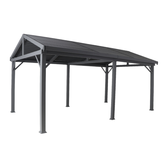
BRIGHTON LOUVRE PANEL GAZEBO
Please carefully read the below warnings and instructions.
!
Save the instructions for future reference.
• Before installing please contact your local council for semi permanent structure requirements.
• For permanent fixture contact your local council and use appropriate fixings.
• This gazebo is a Semi-Permanent structure. Damage caused by extreme weather conditions including heavy rain or high winds is not
covered under warranty.
• Please carefully read all instructions before assembly and use.
• Please separate and identify all parts, ensuring that you have all parts listed.
• To avoid damage to your gazebo, it is recommended that you assemble it on a clean, protected surface.
• Washers must be used when indicated during the assembly process.
• Loosely tighten the nuts and then securely tighten when all are in position. Be careful not to over tighten the nuts during assembly.
• As an added precaution we strongly recommend you tighten any loose components after an initial period of use (around 3-6 months).
For assured longevity and safe use of your gazebo, we recommend regular checking and tightening of any bolts.
IMPORTANT SAFETY INSTRUCTIONS
• The ground for erecting and anchoring the gazebo is required to be a level, solid and a safe surface.
• Beware of existing utilities underground.
• Keep away from any electrical installations and transportation devices.
• Never climb, sit, or stand on the structure.
Assembly Instructions
Item Number: 0262347
Advertisement

Related Manuals for Mimosa BRIGHTON LOUVRE 0262347


Summary of Contents for Mimosa BRIGHTON LOUVRE 0262347
- Page 1 BRIGHTON LOUVRE PANEL GAZEBO Assembly Instructions Item Number: 0262347 Please carefully read the below warnings and instructions. Save the instructions for future reference. • Before installing please contact your local council for semi permanent structure requirements. • For permanent fixture contact your local council and use appropriate fixings. •...
- Page 2 PIECE Q TY r · .. .. .. Leg tube . Leg tube I . . · I Roof frame I · : : 1 Roof frame 1 : : : :1 Roof frame Roof frame 《 Supporting frame 咐 Supporting frame ·I �...
- Page 3 connection plate Roof Edge Panel Cover plate Roof Edge Panel Roof Edge Panel Shutter Shutter Inclined connection plate Leg base cover Leg base cover Supporting Plate Supporting Plate Handle loop cover bracket Corner Bracket...
- Page 4 Corner Bracket Cover plate Angled Connection Bracket Washer Inclined Bracket Drainage Cover Drainage Cover Handle Washer Washer Handle bracket...
- Page 5 Bolt Bolt Bolt Bolt Masonary Bolts Bolt Bolt Bolt Allen key Screw driver Spanner...
- Page 6 Connect the leg base covers (M&M1) to the leg tubes (A &A1) using bolts (AA). Tighten securely using Allen key (JJ) Attach the handle bracket (v) to the leg tube (A1) using bolt (AA) and Allen Key (JJ). Screw in the bolt (DD) into the hole above the handle bracket.
- Page 7 Connect supporting plates (N&N1) to the leg tubes (A ), using bolts (AA). Tighten securely using Allen Key (JJ). M6*18...
- Page 8 Insert the angled connection bracket (R) into the two edge louvre adjustment components (D & D1). Tighten the bolts (AA) using Allen Key (JJ) Repeat the above process for the opposite Connect the handle loop (P) and the edge louvre adjustment components (D &...
- Page 9 Connect the supporting frame (C) and the edge louvre adjustment components (D & D1) with bolts (AA). Tighten securely with Allen Key (JJ). M6*18...
- Page 10 Secure the leg tubes (A & A1) to the edge louvre adjustment components (D & D1) using bolts (AA). Repeat for the other end.
- Page 11 Align the roof frame (B2) between the two leg tubes and connect using bolts (HH). Tighten securely using Allen Key (JJ). Connect roof frame(B2) and leg tubes with the incline stabiliser braces (E &E1), using bolts (CC) & (AA). Tighten securely using Allen Key(JJ)
- Page 12 Connect the roof frame (B&B1) and the leg tubes with the incline stabiliser braces (E& E1), using bolts (CC and AA). Tighten securely using Allen Key (JJ). Connect the two roof frames (B&B1) to the leg tubes, using bolts (HH). Then connect the incline stabiliser braces (E &...
- Page 13 Insert the connection plate (G) into the two roof frame(B&B1). Join the cover bracket (Q) to the roof frame (B&B1) using bolt (AA). Connect the two roof frame (B&B1) to the leg tube(A1)using bolt(AA). Connect the roof frame (B3) to the two roof Connect the frame(B&B1)using...
- Page 14 Cover the roof frame (B & B1&B3) with the corner brackets (Q1) using screws (FF) and screw driver (KK). Refer image below. Attach the inclined connection plate(L) to the roof frame (B &B1), using bolts (AA). Tighten securely using Allen key (JJ).
- Page 15 Insert the connection plate (G1) into the two roof frame(F)using bolt(AA).
- Page 16 Attach the roof frame (F) to the louvre adjusting components (D &D1)and the supporting frame(C1), using bolts (AA). Tighten securely using Allen key (JJ).
- Page 17 Insert the inclined bracket (R2) into the centre louvre adjustment component (D2) and secure using bolts (AA & BB). Tighten securely using Allen Key (JJ). Attach the handle loop (P) to the protruding parts on the lower end of the centre louvre adjustment component (D2), using bolts (GG). Tighten securely using screw driver (KK).
- Page 18 Attach the centre louvre adjustment component (D2) to the roof frame (F& B&B1), using bolts (AA). Secure the other end of (D2) to the inclined connection plate (L) using bolts (AA). Tighten securely using Allen Key (JJ).
- Page 19 Secure the shutter (K1) to the edge louvre adjustment component (D1) with bolt (BB) and washer (U). Secure the other end to the centre louvre adjustment component (D2) in the same way. 24* 8.5*2.5...
- Page 20 Place the washers (U1) between the roof frame (H & F). Place the cover plate (Q3) on the roof frame (H) and after aligning the holes secure with bolt (BB) and washer (U1). Repeat for the other holes. 16* 7*10...
- Page 21 Before installing the shutter (K), use the handle (T) to rotate the louvre arms from position 1 to position 2 (as pictured above).
- Page 22 Insert the shutter(K) as shown, place the edge of the shutter(K)to the tip of the bayonet,then push shutter down until it clicks into place.
- Page 23 Tighten the bolt(AA) Attach the(R1)and corner bracket(Q2)with bolt(AA)
- Page 24 As shown, connect edge adjusting component with roof frame(J&J1),cover drainage cover (S or S1),align the hole,and tighten the bolt(AA).
- Page 25 Your gazebo is now fully assembled. If your gazebo is to be located on a concrete or paved area you can use the included masonary anchors (EE) to secure the gazebo in position. Note: You should check your local council regulations before securing this gazebo permanently.
- Page 26 Please carefully read the below warnings and instructions. Save the instructions for future reference. • Before installing please contact your local council for semi permanent structure requirements. • For permanent fixture contact your local council and use appropriate fixings. • This gazebo is a Semi-Permanent structure. Damage caused by extreme weather conditions including heavy rain or high winds is not covered under warranty.
Need help?
Do you have a question about the BRIGHTON LOUVRE 0262347 and is the answer not in the manual?
Questions and answers