Advertisement
Quick Links
Advertisement

Subscribe to Our Youtube Channel
Related Manuals for Mimosa SIGNATURE PORTSEA


Summary of Contents for Mimosa SIGNATURE PORTSEA
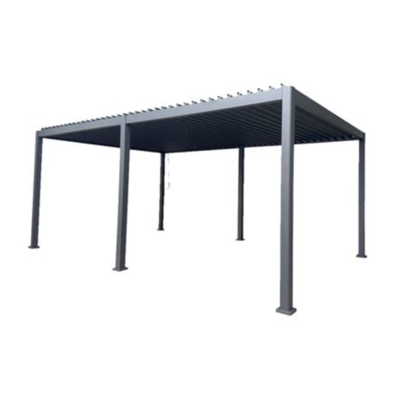
- Page 1 MIMOSA 3.6 × 6M PORTSEA GAZEBO ASSEMBLY GUIDE AND OPERATING INSTRUCTIONS...
- Page 2 MIMOSA 3.6 × 6M PORTSEA GAZEBO...
- Page 3 MIMOSA 3.6 × 6M PORTSEA GAZEBO...
- Page 4 MIMOSA 3.6 × 6M PORTSEA GAZEBO...
- Page 5 MIMOSA 3.6 × 6M PORTSEA GAZEBO...
- Page 6 MIMOSA 3.6 × 6M PORTSEA GAZEBO...
- Page 7 MIMOSA 3.6 × 6M PORTSEA GAZEBO...
- Page 8 MIMOSA 3.6 × 6M PORTSEA GAZEBO STEP 1 Check that no parts are missing from the four boxes. Ensure you have the required tools and safety equipment shown below. STEP 2 Slide a collar (I) over the bottom of one of the leg sections (A) as shown in figure 2, with the rounded part of the collar facing towards the top of the leg.
- Page 9 MIMOSA 3.6 × 6M PORTSEA GAZEBO STEP 3 Repeat the same step for the middle posts. STEP 4 Slide beams B and B1 together and repeat for beams B2 and B3.
- Page 10 MIMOSA 3.6 × 6M PORTSEA GAZEBO STEP 5 Take parts (T1) spacer and (U1) M8 x 45mm screw and tighten with Allen Key (Y) on the B1 beam. Repeat this process on the B2 beam to secure the beam joins in place.
- Page 11 MIMOSA 3.6 × 6M PORTSEA GAZEBO STEP 6 Lay three of the leg sections (A and A1) on the ground as shown below. Take the A1 post and slide the beam (B and B1) into position in the grooves along the top of the post section.
- Page 12 MIMOSA 3.6 × 6M PORTSEA GAZEBO STEP 7 Repeat Step 6 using beams B2 and B3 to secure into the two A1 posts and the centre (A) post.
- Page 13 MIMOSA 3.6 × 6M PORTSEA GAZEBO STEP 8 Working with at least two other people and ensuring everyone is wearing a hard hat , set up two ladders. Lift up one side wall (made up of three legs and beam) and raise one end of the beam (C) above the opening of the post section (A).
- Page 14 MIMOSA 3.6 × 6M PORTSEA GAZEBO STEP 9 Move the ladders to the other side of the structure. Install the other beam (C) onto the open end, using the same method as in Step 8.
- Page 15 MIMOSA 3.6 × 6M PORTSEA GAZEBO STEP 10 Find the corner below along the B beam with the crank pin hanging down. Remove the screw from the crank pin temporarily. Slide the crank loop (V) over the pin, lining up the holes.
- Page 16 MIMOSA 3.6 × 6M PORTSEA GAZEBO STEP 11 Take one of the louvres (D) aside and position as shown below, with the large opening facing up and in front of you. Take the louvre arm plate (L) and position it on the inside of the left end of the louvre.
- Page 17 MIMOSA 3.6 × 6M PORTSEA GAZEBO STEP 12 Move this louvre to the top of the structure, lining up the louvre arm (L) with the crank socket on the B1 rail, just above the crank handle. Insert the crank bolt of the louvre arm into the crank socket.
- Page 18 MIMOSA 3.6 × 6M PORTSEA GAZEBO STEP 13 Back on the other side where the crank handle is, secure the crank bolt from the louvre arm into the socket on the B1 rail using an M6 bolt (U) and washer (T). Tighten with the...
- Page 19 MIMOSA 3.6 × 6M PORTSEA GAZEBO STEP 14 On the other side of the louvre, secure the louvre pin into the second position slot by placing a small cover (M) on top of the slot section, lining up the holes. Screw the cover in...
- Page 20 MIMOSA 3.6 × 6M PORTSEA GAZEBO STEP 15 Repeat steps 13 and 14 for the opposite end of the gazebo.
- Page 21 MIMOSA 3.6 × 6M PORTSEA GAZEBO STEP 16 For each of the remaining 18 louvres, position a louvre plate (K) on the inside of each end. Affix each of the plates into place using two 19mm screws (Q).
- Page 22 MIMOSA 3.6 × 6M PORTSEA GAZEBO STEP 17 For each of the remaining 18 louvres, position a louvre plate (K) on the inside of each end. Affix each of the plates into place using two 19mm screws (Q).
- Page 23 MIMOSA 3.6 × 6M PORTSEA GAZEBO STEP 18 For each of the remaining 36 louvres, position a louvre plate (K) on the inside of each end. Affix each of the plates into place using two 19mm screws (Q).
- Page 24 MIMOSA 3.6 × 6M PORTSEA GAZEBO STEP 19 On the other side of the louvre, secure the louvre pin into the second position slot by placing a small cover (M) on top of the slot section, lining up the holes. Screw the cover in...
- Page 25 MIMOSA 3.6 × 6M PORTSEA GAZEBO STEP 20 On the other side of the louvre, secure the louvre pin into the second position slot by placing a small cover (M) on top of the slot section, lining up the holes. Screw the cover in...
- Page 26 MIMOSA 3.6 × 6M PORTSEA GAZEBO STEP 21 Install one of these louvres into the first position, next to the beam. Ensuring this louvre is in the same orientation as the one already installed, insert the pin on the crank handle end into the first hole position on the B1 rail.
- Page 27 MIMOSA 3.6 × 6M PORTSEA GAZEBO STEP 22 Once all louvres are correctly installed, take the louvre guide rail (G) and line up the holes with the free louvre pins on the crank handle side. Put the louvre guide rail over the pins as shown below.
- Page 28 MIMOSA 3.6 × 6M PORTSEA GAZEBO STEP 23 Position an right-angle plate (N) on top of one of the corners. Use three 19mm screws (R)to affix it into place. Repeat for the remaining corners. ×4 times STEP 23 Secure the feet of the gazebo into the ground. For a hard surface such as concrete or tile, drill holes into the surface through the holes in the feet and install the supplied anchor bolts (W).
- Page 29 MIMOSA 3.6 × 6M PORTSEA GAZEBO...
Need help?
Do you have a question about the SIGNATURE PORTSEA and is the answer not in the manual?
Questions and answers