
Related Manuals for SAES SIP POWER

Summary of Contents for SAES SIP POWER
- Page 1 USER MANUAL SIP POWER ION Pump Controller SAES Getters S.p.A. – Italy www.saesgroup.com M.HIST.0109.23 Rev.1 May 22, 2017 UDOC – CONTROLLED COPY...
- Page 2 The SIP POWER power supply is used for operating the ION element of NEXTorr family pumps. It is designed to be used indoor in laboratory conditions. WARNING After transportation, the device has to be left idle without mains voltage for at least 3 hours at the laboratory temperature.
-
Page 3: Table Of Contents
8. THE OUTPUT CONNECTOR FUNCTION ................27 8.1. Pin layout of IN/OUT Interface connector ..............27 8.2. Analog Output ....................... 28 8.3. RS485 Interface ......................29 USER MANUAL - SIP POWER ION PUMP CONTROLLER M.HIST.0109.23 Rev.1 Page 3 of 62... - Page 4 INSTRUCTION FOR INSTRUMENT DISPOSAL..............56 15. PRODUCT CONFIGURATIONS AND ACCESSORIES ............57 16. WARRANTY CONDITIONS ....................58 17. SERVICE ..........................59 17.1. Sales & Service Locations: ..................59 USER MANUAL - SIP POWER ION PUMP CONTROLLER M.HIST.0109.23 Rev.1 Page 4 of 62...
-
Page 5: Application
2. INTRODUCTION 2.1. General description SIP POWER is the power supply that controls the ion pump (IP) of NEXTorr family. NEXTorr pumps combine in a very compact and unique design Non Evaporable Getter (NEG) and ion pump technologies. SIP POWER can be supplied with alphanumeric display or without display. - Page 6 USER MANUAL - SIP POWER ION PUMP CONTROLLER M.HIST.0109.23 Rev.1 Page 6 of 62...
-
Page 7: Simplified Block Scheme
2.3. Simplified block scheme 2.4. Scheme of the instrument connection USER MANUAL - SIP POWER ION PUMP CONTROLLER M.HIST.0109.23 Rev.1 Page 7 of 62... -
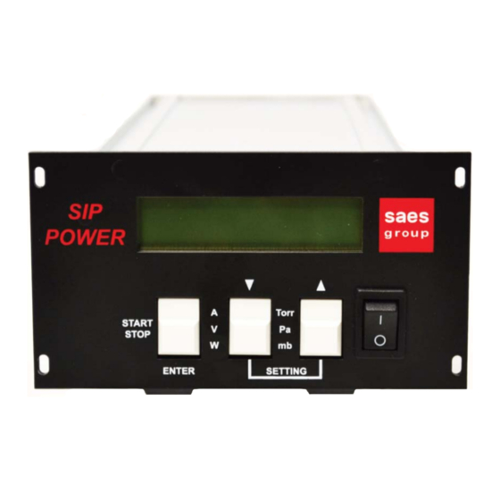
Page 8: The Front Panel Of The Unit
4. Torr/Pa/mb button to change the unit of pressure between Torr, Pascal or mbar respectively 5. ON/OFF instrument power switch 2.6. The rear panel of the unit USER MANUAL - SIP POWER ION PUMP CONTROLLER M.HIST.0109.23 Rev.1 Page 8 of 62... - Page 9 7. USB connector (to record the device parameters on a USB flash memory) 8. SAFETY connector 9. OUTPUT pump connector 10. IN/OUT interface connector with INTERLOCK 11. instrument’s MAININPUT plug USER MANUAL - SIP POWER ION PUMP CONTROLLER M.HIST.0109.23 Rev.1 Page 9 of 62...
-
Page 10: The Front Panel Of The Unit With Leds And Rs485 Interface
Saes Group USB stick with o User manual o SIP power manager: software for remote control via LAN o SIP power controller: software for remote control of one unit via RS485 o SAES product brochures USER MANUAL - SIP POWER ION PUMP CONTROLLER M.HIST.0109.23 Rev.1... -
Page 11: Instrument Dimensions And Weight
SIP POWER weight (all configurations) about 1 kg 220V to 24Vdc power supply unit weighs about 300g and its dimensions are about 12x5x3 cm. 128,5 122,5 111,5 USER MANUAL - SIP POWER ION PUMP CONTROLLER M.HIST.0109.23 Rev.1 Page 11 of 62... -
Page 12: Installation
(rack 3U 19" installation with M3 screws). According to the desired version it is possible to mount/remove four rubber feet. Stand-alone version Mounting on panel USER MANUAL - SIP POWER ION PUMP CONTROLLER M.HIST.0109.23 Rev.1 Page 12 of 62... - Page 13 The circulation of cooling air on the upper/bottom left/right side and behind the device must not be significantly limited when the unit is inserted in a rack or laid on a table. USER MANUAL - SIP POWER ION PUMP CONTROLLER M.HIST.0109.23 Rev.1...
-
Page 14: Electrical Connections
Safety pin of safe cable (2 mm plug) must be inserted into the Safety connector. An enable signal called INTERLOCK must be provided to SIP POWER via IN/OUT interface connector with a closed contact between pins 6-9 and 1-14 (see plot at Sec. 8.1). -
Page 15: Operations
Some ticks are heard during the starting of the power supply belonging to the automatic initialization settings. SIP POWER switches on very rapidly (3-5 seconds) and is immediately ready to locally operate. Remote communication (Ethernet plus USB module) is available after 30 seconds from the switch on of the SIP POWER. -
Page 16: Comparators With Simple Threshold Or Hysteresis
The supply is equipped with other two comparators-switches of the pump current/pressure. These other two switches, SW2 and SW3, can be used to directly connect the SIP POWER with other electronic equipment. Their outputs are led to the IN/OUT INTERFACE output connector. As for SW1, also for SW2 and SW3 the status is shown on the display first line with the symbol of open/close electric switch (more details in the display paragraph). -
Page 17: Operating Ip In Case Of Main Line Interruption
The pin layout of the output connector is described in the Sec.8.1. 4.4. Operating IP in case of main line interruption In case of interruption of line voltage, the SIP POWER restarts in the conditions indicated in section 3.1. For security reasons it is not possible to activate automatic restarts. -
Page 18: Display And Multiple Functions Of Keys
On the first row the following will be shown alternatively: three pieces of information on the working situation, alarm or alarms indications. In order to state to SIP POWER that the indication has been understood and then hide it, press the right key for 5 seconds. - Page 19 Note: the voltage here reported is the actual value measured on the output in real time, without any average, and without any processing. So it is possible that it changes slightly instantly. USER MANUAL - SIP POWER ION PUMP CONTROLLER M.HIST.0109.23 Rev.1...
-
Page 20: Multifunctional Keys
The function of each key is visible on the side of each key (see above image): START / STOP key switches on and off the high voltage supply to the pump USER MANUAL - SIP POWER ION PUMP CONTROLLER M.HIST.0109.23 Rev.1 Page 20 of 62... - Page 21 In order to leave SETTING menu, press at the same time central and right keys for 5 seconds For details on all setting see SETTINGS chapter. USER MANUAL - SIP POWER ION PUMP CONTROLLER M.HIST.0109.23 Rev.1 Page 21 of 62...
-
Page 22: Settings And Service Mode Menu
WINDOW mode. Can be changed from 0nA to 99mA SW2 Max Thr. is the upper hysteresis value in WINDOW mode. Can be changed from 0nA to 99mA (ignored in SIMPLE mode). USER MANUAL - SIP POWER ION PUMP CONTROLLER M.HIST.0109.23 Rev.1 Page 22 of 62... -
Page 23: Sw3 Mode And Sw3 Min Thr. And Sw3 Max Thr
IP address can be changed according to user needs. It is a multifield parameter that allows to set the 4 different bytes of an IP address. IP Netmask field allow you to change Sip Power IP Netmask which is represented in CIDR notation. For example the class 255.255.255.0 = 8+8+8+0 is indicated as 24 MAC Address of ETHERNET-USB card cannot be modified. -
Page 24: Hw. Rev. And Sw. Ver
Hw. Rev. and Sw. Ver. Read only parameter reporting Hardware and Software version of the instrument. Serial Number Read only parameter reporting serial number of the instrument. USER MANUAL - SIP POWER ION PUMP CONTROLLER M.HIST.0109.23 Rev.1 Page 24 of 62... -
Page 25: Abnormal Situation And Alarm Notification
SIP POWER electronic circuit is designed so that this phenomenon is automatically stopped. If arcing is particularly strong or long SIP POWER switches off the voltage supply to the pump for one or two seconds and raises an event. If arcing happens at least three times in less than 45 seconds the supply to the pump is stopped completely. -
Page 26: Input Voltage
25% the rated input voltage. The voltage supplied to the pump is interrupted and restarts automatically when the alarm is cleared. This notification can be useful with the battery pack. It is recommended to switch SIP POWER off immediately when this message is shown. -
Page 27: The Output Connector Function
3 SW2+ positive terminal of comparator switch 2 IP active + positive terminal of switch Operation IP on IN + positive terminal of control input INTERLOCK USER MANUAL - SIP POWER ION PUMP CONTROLLER M.HIST.0109.23 Rev.1 Page 27 of 62... -
Page 28: Analog Output
7). This signal is proportional to logarithm of ion pump current. The limits of the signal are: 0 V for ≤1 nA; 10 V for 100 mA. Pressure scale, must be recalculated accordingly to ion pump sensitivity and chosen pressure unit. USER MANUAL - SIP POWER ION PUMP CONTROLLER M.HIST.0109.23 Rev.1 Page 28 of 62... -
Page 29: Rs485 Interface
Default communication baud rate for RS485 is 38400, 8 data bits, 2 stop-bit, without parity bit, flow control none. Default Modbus slave address is 11 (broadcast is 255). Control of the supply by means of serial interfaces is described in following chapters. USER MANUAL - SIP POWER ION PUMP CONTROLLER M.HIST.0109.23 Rev.1 Page 29 of 62... - Page 30 0x2000 unsigned integer LIFE_TIME total working hours 0x3000 unsigned integer TEMPERATURE internal temperature [K] 0x3001 unsigned integer ARCING_NUMBER number of arcing events from power supply start USER MANUAL - SIP POWER ION PUMP CONTROLLER M.HIST.0109.23 Rev.1 Page 30 of 62...
- Page 31 0x7001 unsigned integer CRITICAL_STEP1 critical step2 bypass command 0x8000 unsigned integer MODBUS_ID power supply Modbus ID 0x8001 unsigned integer LIFE_TIME_RESET total working hours reset USER MANUAL - SIP POWER ION PUMP CONTROLLER M.HIST.0109.23 Rev.1 Page 31 of 62...
- Page 32 Bit 15:2 – Reserved bits These bits are reserved for future use. Bit 1 – Ethernet flag If this bit is set, it means that Sip Power features a Ethernet connection and network registers are addressable. Bit 1 – Display flag If this bit is set, it means that Sip Power features a display on the front panel.
- Page 33 Status Registers These registers are useful to retrieve information about the power supply status. LIFE_TIME – 0x2000 – Total working hours LIFE_TIME[31:24] LIFE_TIME[23:16] LIFE TIME[15:8] LIFE TIME[7:0] USER MANUAL - SIP POWER ION PUMP CONTROLLER M.HIST.0109.23 Rev.1 Page 33 of 62...
- Page 34 This alarm latch is set when the power supply detects a output over-current event. This alarm latch is set only if switch SW1 mode is set to ON and the output current increases over USER MANUAL - SIP POWER ION PUMP CONTROLLER M.HIST.0109.23 Rev.1...
- Page 35 Bit 1 – SW2 Output state This flag shows output status of SW2 switch. Bit 0 – SW1 Output state This flag shows output status of SW1 switch. USER MANUAL - SIP POWER ION PUMP CONTROLLER M.HIST.0109.23 Rev.1 Page 35 of 62...
- Page 36 Bit 15:0 – Output voltage This register shows output voltage in V units (sampled in the same time slice of VIN and IOUT). IOUT – 0x3008 – Output current USER MANUAL - SIP POWER ION PUMP CONTROLLER M.HIST.0109.23 Rev.1 Page 36 of 62...
- Page 37 This register contains output voltage set point in V units. The minimum allowed value is 1000V, the maximum allowed value is 6000V. VOUT_RAMP_INTV – 0x4001 – Output voltage ramping interval VOUT_RAMP_INTV[31:24] VOUT_RAMP_INTV[23:16] VOUT_RAMP_INTV[15:8] USER MANUAL - SIP POWER ION PUMP CONTROLLER M.HIST.0109.23 Rev.1 Page 37 of 62...
- Page 38 0 – SW2 switch is bypassed (OFF) 1 – SW2 switch is in simple mode (SIMPLE) SW1_THR – 0x4004 – Switch SW1 threshold SW1_THR[31:24] SW1_THR[23:16] SW1_THR[15:8] USER MANUAL - SIP POWER ION PUMP CONTROLLER M.HIST.0109.23 Rev.1 Page 38 of 62...
- Page 39 Bit 31:0 – Switch SW2 high threshold These registers contain switch SW2 high threshold in nA units. SW3_THR_MIN – 0x400a – Switch SW3 low threshold USER MANUAL - SIP POWER ION PUMP CONTROLLER M.HIST.0109.23 Rev.1 Page 39 of 62...
- Page 40 CONV_RATE – 0x400e – Conversion rate CONV_RATE[15:8] CONV_RATE[7:0] Bit 31:0 – Conversion rate This register contains the conversion rate in A/Torr units useful to compute chamber pressure from output current. USER MANUAL - SIP POWER ION PUMP CONTROLLER M.HIST.0109.23 Rev.1 Page 40 of 62...
- Page 41 These bytes contains IP network mask (CIDR notation, available only if ETHERNET flag is set in CARD_TYPE register). MAC_ADDR – 0x5003 – Ethernet MAC address MAC_ADDR[47:40] USER MANUAL - SIP POWER ION PUMP CONTROLLER M.HIST.0109.23 Rev.1 Page 41 of 62...
- Page 42 Keepalive timer resets after any successfully processed Modbus frame (frames that rise an exception do not reset keepalive timer). Keepalive interval cannot be lower than 1000 ms, the only exception is 0 ms which disables keepalive timer. USER MANUAL - SIP POWER ION PUMP CONTROLLER M.HIST.0109.23 Rev.1 Page 42 of 62...
- Page 43 Following register are used for special purposes such as changing the slave Modbus ID of the power supply. CRITICAL_STEP1 – 0x7000 – Critical step bypass 1 CRITICAL_STEP1_VALUE[15:8] USER MANUAL - SIP POWER ION PUMP CONTROLLER M.HIST.0109.23 Rev.1 Page 43 of 62...
- Page 44 To change the slave Modbus ID critical step 1 and critical step 2 bypasses have to be previously enabled. LIFE_TIME_RESET – 0x8001 – Salve Modbus ID write LIFE_TIME_RESET_SECRET[63:56] USER MANUAL - SIP POWER ION PUMP CONTROLLER M.HIST.0109.23 Rev.1 Page 44 of 62...
- Page 45 To reset the total working hours counter of the power supply you have to enable critical step1 and critical step2 bypass then write the life time reset secret in LIFE_TIME_RESET register. USER MANUAL - SIP POWER ION PUMP CONTROLLER M.HIST.0109.23 Rev.1...
- Page 46 0x41 – Set IP address command to set IP address and netmask. A payload is required. 0x80 – Read All Answer this command is used only by Sip Power to answer to Read All command. A payload is provided.
- Page 47 Bit 152:183 – Switch SW3 low threshold This field contains switch SW3 low threshold in nA units. This is also SW3 threshold in SIMPLE mode. USER MANUAL - SIP POWER ION PUMP CONTROLLER M.HIST.0109.23 Rev.1 Page 47 of 62...
- Page 48 Bit 0:31 – New IP address This field contains the new Sip Power IP address. Bit 32:63 – New IP network mask This field contains the new Sip Power IP network mask. 10.3. Payload for 0x80 – Read All Answer Command 16bits...
- Page 49 If this bit is set, it means that Sip Power features a Ethernet connection. • Bit 0 – Display flag If this bit is set, it means that Sip Power features a display on the front panel. Bit 16:31 – Hardware revision number This field is structured as follow: •...
- Page 50 • Bit 15:3 – Reserved bits These bits are reserved for future use. • Bit 2 – SW3 Output state This flag shows output status of SW3 switch. USER MANUAL - SIP POWER ION PUMP CONTROLLER M.HIST.0109.23 Rev.1 Page 50 of 62...
- Page 51 Bit 1600:1631 – New IP address This field contains the new Sip Power IP address. Bit 1632:1663 – New IP network mask This field contains the new Sip Power IP network mask. Bit 1664:1671 – MAC address byte 0 ...
- Page 52 In case of dust contamination it can be cleaned by means of a vacuum cleaner. For repair the supply should be shipped back to Saes Group S.p.A.. 11.1. IP troubleshooting During a running mode of the ION pump these messages may be displayed: (for more details see Cap.
- Page 53 38400 Bd, 8 data bits, 2 stop-bit Input voltage 24 Vdc Maximal input current Weight 1 kg Ambient temperature at operation 5÷40 °C Relative humidity 20÷80 % USER MANUAL - SIP POWER ION PUMP CONTROLLER M.HIST.0109.23 Rev.1 Page 53 of 62...
- Page 54 DECLARATION OF CE CONFORMITY USER MANUAL - SIP POWER ION PUMP CONTROLLER M.HIST.0109.23 Rev.1 Page 54 of 62...
- Page 55 USER MANUAL - SIP POWER ION PUMP CONTROLLER M.HIST.0109.23 Rev.1 Page 55 of 62...
- Page 56 The different materials shall be collected separately in accordance with local waste disposal legislations. Neither the collection nor the transport of thus collected and separated materials is subject to any special requirements. USER MANUAL - SIP POWER ION PUMP CONTROLLER M.HIST.0109.23 Rev.1 Page 56 of 62...
- Page 57 Configurations and accessories are given in the following section: Code Product description 3B0506 SIP POWER (with display, standard ETHERNET interface and USB pendrive interface) 3B0507 SIP POWER LOCAL (only with display) 3B0508 SIP POWER LEDS (with standard ETHERNET interface and USB pendrive interface)
- Page 58 This warranty shall only apply to the BUYER and may not be assigned. During the term of the warranty set forth above, SAES will promptly repair the Products which for their features can be repaired and which do not conform to the specifications and which BUYER returns to SAES at the address provided.
- Page 59 SERVICE For a request of return of the component contact a SAES Customer Service and will receive a Return Merchandise Authorization (RMA) number. 17.1. Sales & Service Locations: Europe, Middle East and Africa: SAES Getters S.p.A. Viale Italia 77 20020 Lainate (Milan) - Italy Ph.
- Page 60 USER MANUAL - SIP POWER ION PUMP CONTROLLER M.HIST.0109.23 Rev.1 Page 60 of 62...
- Page 61 SAES GETTERS S.p.A. – Italy www.saesgroup.com This document is property of SAES Group S.p.A The information contained herein is subject to change without notice USER MANUAL - SIP POWER ION PUMP CONTROLLER M.HIST.0109.23 Rev.1 Page 61 of 62...
- Page 62 USER MANUAL - SIP POWER ION PUMP CONTROLLER M.HIST.0109.23 Rev.1 Page 62 of 62...
Need help?
Do you have a question about the SIP POWER and is the answer not in the manual?
Questions and answers
Sip power washer won’t start
The SAES SIP POWER ion pump controller may not start due to the following reasons:
1. Interlock Signal Missing: If the interlock contact is open while the pump is in stop status, the power supply cannot start.
2. Safety Signal Missing: If the safety input signal is not present in stop status, the power supply cannot start.
3. Arcing Protection: If strong or prolonged arcing is detected, SIP POWER switches off the voltage supply to prevent damage.
Checking the interlock and safety connections and ensuring no arcing issues may resolve the startup issue.
This answer is automatically generated
@Oliver Fahy