
Related Manuals for SAES NEG POWER

Summary of Contents for SAES NEG POWER
- Page 1 USER MANUAL NEG POWER NEG Pump Controller NEG POWER starting ... SAES Getters S.p.A. – Italy www.saesgroup.com M.HIST.0101.23 R2 January, 26 2021 * Copy Approved By DCM on 27/01/2021 * Uncontrolled copy when printed...
- Page 2 The NEG POWER - NEG Pumps Controller power supply serves for operating the NEG (Non Evaporable Getters) pumps. It is designed to be used indoor in laboratory conditions. WARNING After transportation, the device has to be left idle without mains voltage for at least 3 hours at the laboratory temperature.
-
Page 3: Table Of Contents
5.2. RS232 / RS485 Interface .................... 23 Electrical Specifications ..................... 24 Summary Table of the NEG Pumps controlled by the NEG POWER ......25 PRODUCT CONFIGURATIONS AND ACCESSORIES ..........26 8.1. NEG POWER configurations and accessories: ............26 ... -
Page 4: Application
There are two versions: NEG POWER for up to 4 controlled pumps, NEG POWER SMALL supporting up to 2 pumps only. NEG POWER can control up to 4 different getter pumps at the same time, with an adjustable DC voltage output up to 110 V, current up to 10A, power up to 700W. -
Page 5: Main Features
Low power modules of 150 W can be also installed in the NEG POWER to work in the low range of power with the smallest SAES NEG pumps requiring low values of power / voltage / current with a precision around ±... -
Page 6: Neg Power: The Front Panel Of The Unit
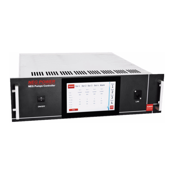
2.5. NEG POWER: the front panel of the unit 1. ON/OFF instrument power switch 2. touch screen display 3. LAN connector: RJ45 connector for Ethernet 4. handles for transport 2.6. NEG POWER: the rear panel of the unit 5. instrument MAININPUT IEC 16 A: plug for mains power supply 6. -
Page 7: Neg Power Small: The Front Panel Of The Unit
2.7. NEG POWER SMALL: the front panel of the unit 14. touch screen display 2.8. NEG POWER SMALL: the rear panel of the unit 15. instrument MAIN INPUT IEC 16 A: plug for mains power supply 16. ON/OFF instrument power switch 17. -
Page 8: Neg Power Dimensions And Weight
2.9. NEG POWER Dimensions and Weight NEG POWER dimensions 19” rack, 3U, depth 460 mm NEG POWER weight (with 1 power module) 10 kg NEG POWER weight (with 2 power modules) 12 kg NEG POWER weight (with 3 power modules) 13.5 kg... -
Page 9: Installation
Insert the instrument in the appropriate space (19” rack 3U according to DIN 41494 standard). Fix the NEG POWER front panel on the rack columns with four M6 screws. NEG POWER SMALL is half 19” rack large. It is prepared with lateral holes to fix it on rack with two brackets. -
Page 10: Cleaning
3.3. Cleaning ATTENTION: before starting any cleaning turn the units off and remove all mains. The units should be cleaned with a damp cloth when necessary. The use of solvents an aggressive or scouring cleaning agent is not permitted. Avoid spraying or spilling any type of liquid directly onto the unit. Before putting the units into operation mode to check them that are thoroughly dry. -
Page 11: Mode Of Operation
4. MODE OF OPERATION NEG POWER has a touch screen display to control all the pumps together and in a very friendly way; it is also possible to control the NEG POWER by the SAES remote control software. The most popular SAES NEG pumps are preset in the software (like the GP SORB AC, the CapaciTorr, CapaciTorr HV and NEXTorr families). -
Page 12: The General Setup Button
4.3. The General Setup button A Setup button is present in the General menu. It allows to access menus of instrument settings: Date and time settings, Network settings, Modbus Server Settings, Output Channel Settings, Brightness and Standby time. SAVE button saves the changes. BACK button leaves the menu. REBOOT button restarts the firmware. - Page 13 Log files are stored in RAM so they are lost after power off cycle. NEG POWER is able to detect the Output Insulation Losses making a check between positive/negative power wire and ground wire or between thermocouple wires and ground wire.
- Page 14 System settings: choose the screen brightness and standby delay (from 0 = never to 4 hours of inactivity). M.HIST.0101.23 R2 Page 14 of 36 January, 26 2021...
-
Page 15: The Setup Menu
(for example CapaciTorr D1000 in the example below). The system shows automatically the list of SAES pumps that can be controlled with that output. In the left example picture below a list of pumps for standard 700 W module is shown, whereas the right picture shows the list that will appear when the low power module (150 W module) is installed. - Page 16 Selecting the pump model, the recommended settings are preloaded (instructions to change these values are reported at point 4). please note that these settings are for pumps without jackets. CABLE is an automatic recognition of the cable length (if the cable supports the feature). It can not be changed by the user.
-
Page 17: The Limit Setup Button
Let’s assume that the working point of the NEG POWER is V = 10V I = 5A so P = 50W and T = 400°C NEG POWER stays in this working point because the output has reached Vmax and cannot exceed it. -
Page 18: The Save And Cancel Buttons
4.6. The SAVE and CANCEL buttons For each channel there are two independent presets: one for activation and one for conditioning. Presets can be saved to permanent memory or changes can be cancelled restoring previous settings. SAVE CANCEL 4.7. The START/STOP buttons START / STOP buttons are the first indicator of the status of the output. -
Page 19: The Recommended Settings
All parameters are adjustable in the setup menu, but every change of selected pump model or of operating mode (Activation/Conditioning) restore the default settings. When you turn off and turn on NEG POWER, the last settings and used parameters are presented and you can use again pressing start button without any other change. This happens because NEG POWER stores permanently the current parameters when you press start button. -
Page 20: Heating (Activation/Conditioning) Without Stop
Some applications require special getter pumps (HV) that work when the getter material is hot. NEG POWER can be used to keep these pumps hot giving them the necessary power continuously. To do this, t_hold = is used (to set t_hold = reduce t_hold down to 100 and press down again). -
Page 21: Alarms
4.11. Alarms If there are problems during the control of NEG pumps, the output status is ALARM and the output start / stop button is disabled. The status is ALARM until the problem is solved. When an alarm occurs, a red bar appears on the screen with detailed information of the problem. Touch the red bar to acknowledge the alarm. -
Page 22: Alarm History
4.13. Information page Touching SAES logo an information page appears. The software versions, serial numbers and general system information are here listed. Please, note that Service page is a sub menu for service use only. M.HIST.0101.23 R2... -
Page 23: The Output Connector Function
5. THE OUTPUT CONNECTOR FUNCTION The output connectors can be used for a possible connection of a device designed for monitoring or controlling the supply activity. IN/OUT INTERFACE is intended for connection to protective hardware systems; LAN connector can be used for communication purposes via ETHERNET interface in MODBUS TCP protocol. -
Page 24: Electrical Specifications
Low power modules Output1-4 at 30 V: Output power 150 W + overload Output Voltage 0-30 V Overload 110% for one minute Supply Current NEG POWER models Maximum Rated Current 3B0501-3B0502-3B0503-3B0504 20 A 3B0521-3B0522-3B0523-3B0524 10 A 3B0525-3B0526-3B0527 20 A 3B0528-3B0529-3B0530... -
Page 25: Summary Table Of The Neg Pumps Controlled By The Neg Power
7. Summary Table of the NEG Pumps controlled by the NEG POWER GP PUMPS Activation Activation Activation Model Pump Notes Voltage (nude) Current (nude) Power (nude) Temperature [°C ] GP 50-2F st 707 (450°C) NO TCK GP 50-2F st 101 (700°C) NO TCK... -
Page 26: Product Configurations And Accessories
NEG POWER LP C4 3B0524 Controller for NEG Pumps ( 4 outputs low power) Additional low power module Power module to upgrade NEG POWER LP NEG POWER hybrid S1L1 C2 3B0525 ( 1 output standard power and 1 output low power ) -
Page 27: Pump Cables And Accessories
8.2. Pump cables and accessories: Product description Codes: length 3m length 5m length 10m Cable supply output for MK4 type pumps 3B0345 3B0356 3B0353 Cable supply output for MK5 type pumps 3B0337 3B0361 3B0364 and for CapaciTorr D2000 and D3500 pumps Cable supply output HT for MK5 type pumps 3B0393 3B0394... -
Page 28: Declaration Of Ce Conformity
9. DECLARATION OF CE CONFORMITY M.HIST.0101.23 R2 Page 28 of 36 January, 26 2021... -
Page 29: Instruction For Instrument Disposal
INSTRUCTION FOR INSTRUMENT DISPOSAL The instrument disposal has to be carried out in compliance with the user’s country applicable regulations. The information below is issued in compliance with the regulations as set out by the 2012/19/EU directive (Waste Electrical and Electronic Equipment). The instrument contains materials which may endanger the environment and it’s not allowed to dispose it with unsorted urban waste. -
Page 30: Warranty Conditions
This warranty shall only apply to the BUYER and may not be assigned. During the term of the warranty set forth above, SAES will promptly repair the Products which for their features can be repaired and which do not conform to the specifications and which BUYER returns to SAES at the address provided. -
Page 31: Service
12. SERVICE For a request of return of the component contact a SAES Customer Service and will receive a Return Merchandise Authorization (RMA) number. SAES S.p.A. can not accept any instrument which contains radioactivity or contamination of hazards: biological, toxic, reactive, corrosive, explosive or flammable. If this requirement present a problem call SAES Customer Service to discuss alternatives solutions. -
Page 32: Appendix A: Supply Cables
APPENDIX A: Supply cables GP100 MK4, GP200 MK4, GP500 MK4. For these pumps which are equipped with a dedicated electrical connector, use output supply shown in figure: REAR VIEW OF CONNECTORS BLUE YELLOW/GREEN BROWN BLUE BROWN YELLOW/GREEN POSITIVE-RED POSITIVE - RED NEGATIVE - GREEN NEGATIVE - GREEN TO NEG PUMP CONTROLLER... - Page 33 GP100 MK5, GP200 MK5, GP500 MK5, CapaciTorr D2000, CapaciTorr D3500 For these pumps which are equipped with a dedicated electrical connector, use the output supply cable shown in figure: REAR VIEW OF CONNECTORS POSITIVE - RED BLUE YELLOW/GREEN NEGATIVE - GREEN BROWN YELLOW/GREEN BROWN...
- Page 34 CapaciTorr D1000, NexTorr D300-5, NexTorr D500-5, NexTorr D1000-10, NexTorr D2000-10 For this pump which are equipped with a dedicated electrical connector, use the output supply cable shown in figure: REAR VIEW OF CONNECTORS ALUMEL CHROMEL BLUE YELLOW/GREEN BROWN YELLOW/GREEN NOT USED BROWN ALUMEL CHROMEL...
- Page 35 (BLANK PAGE) M.HIST.0101.23 R2 Page 35 of 36 January, 26 2021...
- Page 36 SAES GETTERS S.p.A. – Italy www.saesgroup.com This document is property of SAES Group S.p.A The information contained herein is subject to change without notice M.HIST.0101.23 R2 Page 36 of 36 January, 26 2021...
Need help?
Do you have a question about the NEG POWER and is the answer not in the manual?
Questions and answers