Table of Contents
Advertisement
Quick Links
Advertisement
Table of Contents

Related Manuals for Asko DC7794


Summary of Contents for Asko DC7794
- Page 1 User manual DRYING CABINET ASKO DC7794HP...
- Page 3 ASKO offers you all these features. When you buy an ASKO product, you can be sure that the inside is just as good as the outside and that the ethics and morality that go into building this product are just as high as the quality and function you are getting.
-
Page 4: Table Of Contents
CONTENTS THIS USER MANUAL OPERATION User tips SAFE OPERATION Drying programme Selecting a drying programme Technical safety Starting the drying programme FOR A GOOD ENVIRONMENT Stopping the drying programme Packaging material The door is opened Dealing with an old drying cabinet SETTING THE DRYING PROGRAMME DESCRIPTION OF THE DRYING... -
Page 5: This User Manual
THIS USER MANUAL The contents of this user manual describe the drying cabinet’s functions and how it should be used. It also includes instructions for installation, reversing the door and maintenance. It also contains a service appendix. -
Page 6: Safe Operation
SAFE OPERATION This advice and the warnings on safe operation have been compiled so that you can avoid incorrect use and unnecessary risks of accidents, and should be read before the drying cabinet is installed and used. WARNING! This drying cabinet fulfils the relevant safety requirements. - Page 7 SAFE OPERATION Check that the information on the drying cabinet rating plate (fuse, ■ voltage and frequency) is consistent with the mains electricity supply. Do not use an extension lead to set up the electrical connection ■ for the drying cabinet, because the necessary safety cannot be guaranteed (risk of overheating).
-
Page 8: For A Good Environment
FOR A GOOD ENVIRONMENT Packaging material Dealing with an old drying cabinet The packaging material that protects the drying cabinet against transport Once the drying cabinet reaches the damage has been selected with end of its life, it must be disposed of for consideration of the environment and recycling. -
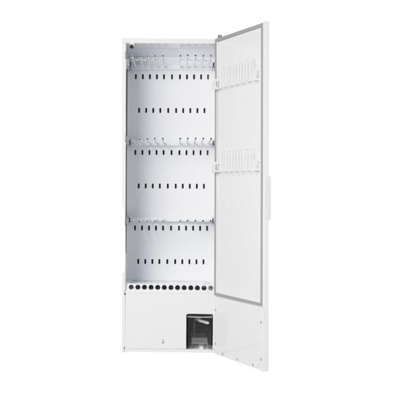
Page 9: Description Of The Drying Cabinet
DESCRIPTION OF THE DRYING CABINET The ASKO DC7794HP drying cabinet process, and the water that is formed is works according to the same principle conveyed to a detachable water tank, or as a heat pump, with a dehumidifier unit via a hose to the drain. -
Page 10: Air Flow In The Cabinet
AIR FLOW IN THE CABINET Air inflow in 6 rows of holes Cleaning filter beneath the shoe rack Return air after dehumidification. Goes into a duct on the back of the drying cabinet. Dehumidifier unit Make sure that shoes and similar items placed in the cabinet do not block the air flow! -
Page 11: Control Panel
CONTROL PANEL The drying cabinet is equipped with two drying programmes for different types of garments. These programmes are set through programming menus using four buttons on the menu panel. Several languages can be used. ARROW UP, increases the value or steps in one direction through the programmes. -
Page 12: Language Setting
CONTROL PANEL Language setting The following languages can be used: English, Swedish, Norwegian, Danish and Finnish. Make sure that the drying Step through to the desired cabinet’s main ON/OFF switch is language using the ARROW UP off. The display is not lit. and DOWN buttons. -
Page 13: Positioning The Drying Cabinet
POSITIONING THE DRYING CABINET An earthed electrical socket must ■ be within a distance of 2 m from the bottom of the drying cabinet. The drying cabinet has a 2 m long earthed cable with plug attached at the bottom. The electrical socket must be located so that no extension lead needs to be used. -
Page 14: Condensation Water
CONDENSATION WATER Condensation water can be discharged in two ways, either by being collected in a detachable water tank or by being conveyed through a hose to the floor drain. Detachable water tank The water tank is dimensioned to be easily adequate for a complete wash. -
Page 15: Connection To Floor Drain
CONDENSATION WATER Connection to floor drain The drying cabinet is supplied from the factory with a hose to the detachable water tank. To change to discharging condensation water to a floor drain, proceed as follows: Carefully pull the upper part of the hose out around 2-3 cm. Cut off the hose in the middle of the opening. -
Page 16: Installation
INSTALLATION Unpacking Check that the product has not been Check that all transportation securing damaged in transit. Any damage in devices have been removed before transit must be reported to the retailer connecting the drying cabinet. within 7 days. Packaging materials such as plastic After unpacking, check that the and styrofoam should be kept out of product is free of faults. -
Page 17: Reversing The Door
INSTALLATION Reversing the door The cabinet is supplied from the factory right-hung. The door can subsequently be rehung on the opposite side. A rehanging set is required to rehang the door. This can be ordered as a spare part. Rehanging set Connector for cables. - Page 18 INSTALLATION Lay the door down carefully with the inside facing upwards. Undo all the screws holding the upper panel in place. The screws are located under the magnetic strips. Remove the hangers and lift off the panel together with the magnetic strip.
- Page 19 INSTALLATION Move the lower hinge (9) to the other side. The hinge should be reversed and the hinge pin unscrewed and remounted on the other side of the hinge.. Make sure that the hinge pin is tightened securely. Lower hinge Place the door on the cabinet and take the new upper hinge and carefully thread in the new cable.
-
Page 20: Placement/Attachment
INSTALLATION Placement/attachment The drying cabinet is only designed for operation indoors in a dry environment. Attachment bracket The drying cabinet should not be installed in a location where high pressure water is used for cleaning. LEVELLING The drying cabinet should stand level on a flat surface, resting on all four feet. -
Page 21: Electrical Connections
INSTALLATION Electrical connections The drying cabinet should be connected to a 230V single-phase 50 - 60 Hz earthed socket. The drying cabinet is supplied ready for connection with a cable with an earthed plug. The drying cabinet should be connected using the cable supplied to an earthed wall socket, and must not be permanently connected! The socket should be located where... -
Page 22: Start-Up
START-UP Read this user manual WARNING! before using the drying Read the safety instructions on page cabinet for the first time. 5 before using the drying cabinet. Check that the cabinet is firmly attached to the wall. See page 19. Check that no packaging material has been left behind. -
Page 23: Operation
OPERATION The cabinet contains three sections with hangers. Each section has a number of bars on which to hang the washing. Hang the articles in the drying cabinet according to how much space they ■ require, not according to their weight. Turn up the two bottom hanger sections if long garments are to be dried. -
Page 24: User Tips
OPERATION User tips Always follow the washing instructions on garments if such instructions are ■ provided. If fabric softener or antistatic product is used, the manufacturer’s instructions ■ concerning its use should be followed. Remove washing that is already dry. This will reduce the drying time for ■... -
Page 25: Drying Programme
OPERATION Drying programme The drying cabinet is equipped with two automatic drying programmes: NORMAL DRY ■ EXTRA DRY ■ THE PROGRAMMES SWITCH THE DRYING PROCESS OFF AUTOMATICALLY WHEN THE ITEMS OF CLOTHING ARE DRY. Selecting a drying programme NORMAL DRY – Used for drying of garments of normal thickness. ■... -
Page 26: Starting The Drying Programme
SETTING THE DRYING PROGRAMME Starting the drying programme MOST RECENTLY USED DRYING PROGRAMME ■ Press the ON/OFF switch to the “ON” position, indicated by the display lighting up and showing the most recently run programme. If this is the programme you want, press START/STOP. Otherwise choose another drying programme by stepping UP or DOWN with the arrow keys. -
Page 27: Stopping The Drying Programme
SETTING THE DRYING PROGRAMME PROGRAMME END ■ When the cooling period has ended, the drying process is finished, and the display shows the text (flashing). “END” When the START/STOP button is pressed after the door is opened, the current programme is stopped and the display shows the most recently used programme. In waiting mode the display goes off Empty the condensation water tank after 15 min and lights up again when... -
Page 28: Introduction
SETTING THE DRYING PROGRAMME There are options for optimising the drying cabinet’s two drying programmes for best results. The setting is adjusted on the control panel for the programme concerned. This is only to be done if you find that: The washing is not dried sufficiently. -
Page 29: Procedure
SETTING THE DRYING PROGRAMME Procedure The drying cabinet’s parameter list is accessed through the control panel. The parameter list is shown as follows: on the top row of the display the current value is shown, e.g. P 2071, on the bottom row the set value of the parameter is shown. Make sure that the drying cabinet’s main ON/OFF switch is off. -
Page 30: Care
CARE Cleaning Brush the cleaning filter clean with the brush supplied. Replacement parts High-pressure cleaning should not be If the connecting cable is damaged used! for any reason, it must be replaced. Genuine parts can obtained from the cabinet retailer. Cleaning and maintenance must not be performed by children without supervision. -
Page 31: Service
This information can be found on the rating plate located inside the cabinet. Rating plate (inside) ASKO DC 7794HP Name of the drying cabinet Article number Serial number (12 digit) -
Page 32: Troubleshooting
TROUBLESHOOTING Issues Action The drying cabinet 1. Check that the mains lead is plugged in. does not work 2. Check that no fuse has blown. 3. Have you pressed the start button? 4. Is the door closed? 5. Is the water tank in position and empty? The display shows 1. - Page 33 TROUBLESHOOTING Issues Action The display shows SHOULD BE CARRIED OUT BY A SERVICE ENGINEER CLOSE THE DOOR 1. Check that the door seals correctly so that the door switch is activated. (The switch is located at the bottom of the cabinet on the cover panel in front of the heat pump unit).
- Page 34 TROUBLESHOOTING Issues Action The sealing strip 1. Check that the cabinet is level. Check with a spirit level and adjust the adjustable feet if necessary. does not seal tightly / the door is ajar 2. Check that the cleaning filter and its holder are correctly installed.
- Page 35 TROUBLESHOOTING Mounting screws for grille Grille over the tray and then shoe stand and lint filter removed Mounting plate Foam cover over pump Foam cover and mounting plate...
- Page 36 TROUBLESHOOTING Float Bracket for micro- switch and moisture sensor Here the foam cover and mounting plate have been removed Lock plate Door switch Front panel with door switch...
-
Page 37: Fault Code List
FAULT CODE LIST Describes the relevant fault codes for this product. Name Description FAULT 03 Fault in moisture Sensor is outside its range sensor FAULT 04 Maxtid process Maximum time for drying process exceeded (the preset value 180 min can be changed using parameter P 2073). -
Page 38: Technical Data
TECHNICAL DATA Capacity: approx. 4.0 kg washing (cotton) Dewatering capacity: 22 g/min Electrical connection: single-phase 220 - 240 V, 50 Hz, 10A Output: 900 W Capacity of main fan: 945 m³/h (free blow) Capacity of secondary fan: 160 m³/h (free blow) 16 metres Hanging length: Dimensions:... - Page 39 TECHNICAL DATA ENERGY CONSUMPTION AND DRYING TIME WHEN DRYING SPUN WASHING * Programme Energy consumption Drying time Temp. max kWh/kg washing NORMAL DRY 90 min 55 °C EXTRA DRY 120 min 55 °C * Values may vary depending on: spin speed ■...
-
Page 40: Service Appendix
SERVICE APPENDIX Electrical diagram -XM4.2 -XA1.X7 -XM4.1 -XA1.X6 -XM3.2 -XA1.X5 -XS3.2 -XM3.1 -XA1.X4 -XS3.1 -XM2.1 -XA1.X3.3 -XM2.2 -XA1.X3.2 -XM2.3 Lamp -XA1.X3.4 -XM1.3 Heater -XM1.2 -XM1.1 -XC1.3 -XC1.2 -XC1.1 106159-0... -
Page 41: Removing The Dehumidifier Unit
SERVICE APPENDIX Removing the dehumidifier unit The dehumidifier unit consists of a closed unit in the bottom of the cabinet. The entire unit must be removed for servicing. Dehumidifier unit FROM REAR Undo the cabinet from the wall and turn it so that you can access the rear. - Page 42 SERVICE APPENDIX After completing the service, fit the unit inside the drying cabinet in the reverse order. Once the cabinet is in place, it is very important that the cabinet is secured to the wall. The door switch (3) is fitted to the front panel (4).
- Page 43 SERVICE APPENDIX FROM FRONT Remove the shoe stand and dismantle the filter holder. Remove the cover plugs and detach the front panel held in place with 2 screws (2) (torx T20). Detach the cable for the door switch (3). Detach the network cable and communication cable. Remove the water tank.
- Page 44 We reserve the right to make changes. en (05-15) ASKO DC7794HP...
Need help?
Do you have a question about the DC7794 and is the answer not in the manual?
Questions and answers