LABORIE NXT Pro Manuals
Manuals and User Guides for LABORIE NXT Pro. We have 2 LABORIE NXT Pro manuals available for free PDF download: Owner's Manual
LABORIE NXT Pro Owner's Manual (128 pages)
Brand: LABORIE
|
Category: Medical Equipment
|
Size: 5 MB
Table of Contents
-
Introduction12
-
Intended Use12
-
Quick Start19
-
Flow Phase36
-
Tests42
-
Stress Test42
-
Login45
-
Settings50
-
Admin51
-
Patients51
-
Symptoms55
-
Workflows58
-
Reports69
-
Editing69
-
Video Images72
-
Review74
-
Cleaning82
-
Disinfection85
-
Backups97
-
Hardware102
-
AIO Computer102
-
Roam NXT106
-
Pim Nxt106
-
Urocap NXT110
-
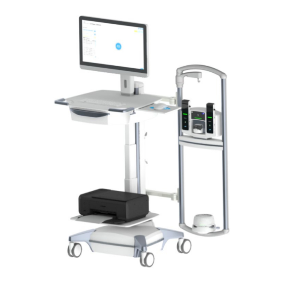
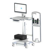
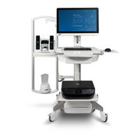
NXT Pro Cart112
-
UPP Puller NXT113
-
EMG Electrodes116
-
Commode116
-
Appendix117
Advertisement
LABORIE NXT Pro Owner's Manual (116 pages)
Brand: LABORIE
|
Category: Medical Equipment
|
Size: 5 MB
Table of Contents
-
Introduction12
-
Intended Use12
-
Quick Start18
-
Flow Phase29
-
Tests35
-
Stress Test35
-
Login37
-
Settings42
-
Admin43
-
Patients43
-
Symptoms47
-
Workflows50
-
Reports60
-
Editing60
-
Video Images63
-
Review65
-
Cleaning73
-
Disinfection76
-
Backups87
-
Hardware93
-
AIO Computer93
-
Roam NXT97
-
Urocap NXT100
-
NXT Pro Cart103
-
EMG Electrodes105
-
Commode105
-
Appendix106