Advertisement
Quick Links
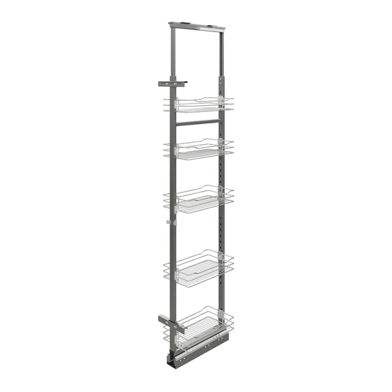
Assembly guide
Component parts
2 x Frame connectors (B)
Frame (A)
Basket (F)
Installed height x 1165 mm = 4 Storage baskets
Installed height x 1685 mm = 5 Storage baskets
Installed height x 1935 mm = 6 Storage baskets
Check off components as shown in diagram and lay on flat surface
1
Working outside of the carcase, secure the two part frame (A) together by
inserting 1 x M4 x 10.0 mm flat head screw (O) into one end of a M5 x 22.0 mm
threaded insert (N). Then place 1 x frame connector (B) into the bottom section of
frame (A) and align the connection holes. BE CAREFUL NOT TO LET THE FRAME
CONNECTORS SLIP DOWN INSIDE THE MAIN FRAME! Insert the M5 x 22.0 mm
threaded insert with the already fitted screw in one side, through the already aligned
holes in the frame. Secure using another M4 x 10.0 mm flat head screw (O). Repeat
process for the other side and top half of frame.
Side mounting pull-out Larder units:
2 x Runners (C)
3 x Door panel
hanging brackets (D)
3 x Door panel
hanging plates (E)
2 x Door panel
connectors (G)
Flat head screw (O)
Threaded insert (N)
Flat head screw (O)
Sales and Technical Support -
Sales and Technical Support -
Tel: 01788 542020, Fax: 01788 544440, E-Mail: info@hafele.co.uk
Tel: 01788 542020, Fax: 01788 544440, E-Mail: info@hafele.co.uk
Tools required (Not Supplied)
Spirit Level
Cross Head Screwdriver
Pencil
Did you know Häfele also supply tools to the trade and industry?
See www.hafele.co.uk for more information.
•
Make sure all the components are included before
you start.
•
The number for technical support is at the bottom
of the page.
•
Don't rush!
•
Read the instructions first.
•
Assemble in the stages shown.
•
Keep the fittings together to avoid loss.
•
Have fun.
2 x M6 mm x 10 mm
12 x M5 x 6.0 mm
Round head bolt (H)
Round head bolt (I)
4 x M6
locking washer (K)
4 x M5 x 22.0 mm
8 x M4 x 10.0 mm
Threaded insert (N)
Flat head screw (O)
2
Secure the top runner (C) to the frame (A) using
2 x M6 locking washers (K), and 2 x M6 Hexagon
nuts (L).
500.00-0100
FITT-10059
Issue - 01
Bradawl
Tape measure
36 x M4 x 15 mm
Pan head screw (J)
4 x M6
Hexagon
pin caps
nuts (L)
x 2 per pin (M)
48 mm pins
x 2 per basket (P)
Advertisement

Subscribe to Our Youtube Channel
Related Manuals for Häfele Side mounting pull-out Larder unit


Summary of Contents for Häfele Side mounting pull-out Larder unit
- Page 1 500.00-0100 FITT-10059 Issue - 01 Assembly guide Side mounting pull-out Larder units: Tools required (Not Supplied) Component parts Bradawl Spirit Level Tape measure 2 x Frame connectors (B) Cross Head Screwdriver Pencil 2 x Runners (C) Did you know Häfele also supply tools to the trade and industry? See www.hafele.co.uk for more information.
- Page 2 Assembly guide Side mounting pull-out Larder units: Steps 3 to 6 Steps 3 to 6 Front edge of carcase Digram 1 Position bottom runner (C) to the internal side of the carcase at floor level with the front fixing hole centre 43 mm from the front edge of the carcase.
- Page 3 Assembly guide Side mounting pull-out Larder units: Step 7 to 9 Step 7 to 9 A= 257 mm + door overlay Installed unit height 1165, B = 800 mm Installed unit height 1685, B = 1175 mm Installed unit height 1935, B = 1400 mm C = 10.0 mm + door overlay D = 239 mm for a 300 mm carcase Attach the top &...
- Page 4 Assembly guide Side mounting pull-out Larder units: Step 10 to 12 Step 10 to 12 Adjustment of the door can be achieved by partially unscrewing, Screws 1 for horizontal adjustment, screw 2 for vertical adjustment, until the desired position is achieved. Screws 3 can then be losened / tightened for in and out adjustment.
Need help?
Do you have a question about the Side mounting pull-out Larder unit and is the answer not in the manual?
Questions and answers