Table of Contents
Advertisement
Quick Links
CLEVER
ASSEMBLY INSTRUCTIONS
Required Tools:
#2 Phillips Driver
Metric Allen Wrenches
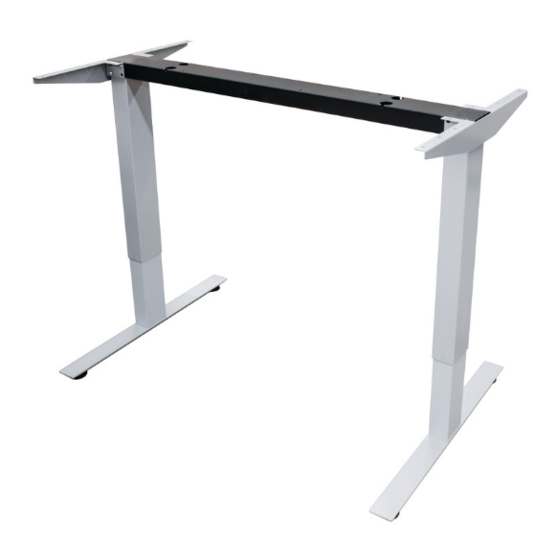
Clever Columns
Clever Feet
Control Box
Table Kit Includes:
2 Clever Columns 1 Cross Beam with Motors 2 Feet
2 Top Supports Control Box Hand Switch Hardware
Cross Beam with Motors
Clever Top Supports
Or
Independent Beams with Motors
Hand Switch
Hardware Included
M10 x 50mm Button Head
QTY 4
M8 x 12mm Button Head
QTY 8
#
/
Wood " re
QTY 20
0000.2299-A
Advertisement
Table of Contents

Related Manuals for Häfele CLEVER


Summary of Contents for Häfele CLEVER
- Page 1 ASSEMBLY INSTRUCTIONS Table Kit Includes: Required Tools: 2 Clever Columns 1 Cross Beam with Motors 2 Feet #2 Phillips Driver Metric Allen Wrenches 2 Top Supports Control Box Hand Switch Hardware...
- Page 2 CLEVER ASSEMBLY INSTRUCTIONS All ele tri otors MU“T e i itialized efore o i g the ta le i the UP dire tio . Please follow the below instructions for proper initialization: 1. All Columns (motors) must be plugged into the Control box.
- Page 3 ASSEMBLY INSTRUCTIONS Step 1 - Insert Clever Column into Cross Beam and slide Top Supports over the width of the Beam. (Fig. 1) Step2 - Attach the Top Supports to the Clever Column using the M8x12mm Button Head Screws provided.
- Page 4 CLEVER ASSEMBLY INSTRUCTIONS Clever Feet Step 3: Attach the Clever Feet using the (Fig. 3) M10x50mm Button Head screws provided. (Fig. 3) Step 4: After Step 3 is complete, flip the assembly right side up (in the operating position). 0000.2299-A...
- Page 5 CLEVER ASSEMBLY INSTRUCTIONS Step 5: Attach Top Supports and Cross Beam to the table top with the #10 x 3/4" Wood Screws provided. (Fig. 4) Step 6: Attach Control Box and Hand Switch underneath the work surface. Center the control box on the opposite side of the user next to the Cross Beam.
Need help?
Do you have a question about the CLEVER and is the answer not in the manual?
Questions and answers