Table of Contents
Advertisement
Quick Links
Before commencing assembly, please read these instructions thoroughly.
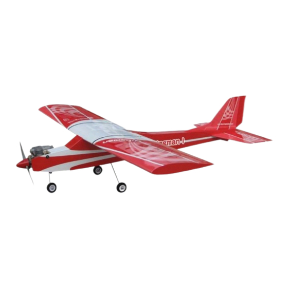
Wing Span: 60 in / 1525 mm
Wing Area: 620 sq in / 40 sq dm
Flying Weight: 3.7 lbs / 1680 g
Fuselage Length: 48.5 in / 1235 mm
Requires: (Engine powered) 2-stroke 0.40 engine
Warning ! This model is not a toy.
It is designed for maximum performance. Please seek advice if one is not familiar with this kind
of engine(electric) powered precision model. Operating this model without prior preparation may
cause injuries. Remember, safety is the most important thing. Always keep this instruction
manual at hand for quick reference.
* Specifications are subject to change without notice.*
THE WINGS MAKER
FACTORY PRE-FABRICATED
ALMOST-READY-TO-FLY (ARF) SERIES
MADE IN CHINA
www.thewingsmaker.com
GA027PO25971103
All manuals and user guides at all-guides.com
Specifications
4-channel radio w/ 4 standard servos
(Electric powered) 450W motor system
4-channel radio w/ 3 standard servos
40A brushless ESC with 11x8E propeller,
4 cells 14.8V 3200 mAh Li- Po battery & charger
INSTRUCTION MANUAL
Advertisement
Table of Contents

Related Manuals for The Wings Maker Wingman I


Summary of Contents for The Wings Maker Wingman I
- Page 1 Operating this model without prior preparation may cause injuries. Remember, safety is the most important thing. Always keep this instruction manual at hand for quick reference. * Specifications are subject to change without notice.* THE WINGS MAKER FACTORY PRE-FABRICATED ALMOST-READY-TO-FLY (ARF) SERIES MADE IN CHINA www.thewingsmaker.com...
-
Page 2: Before You Begin
All manuals and user guides at all-guides.com I N D E X BEFORE YOU BEGIN P. 1 PARTS LIST P. 2 ASSEMBLY P.3-P.12 SAFETY PRECAUTIONS P.12 BEFORE YOU BEGIN Read through the manual before you begin, so you will have an overall idea of what to do. Check all parts. - Page 3 All manuals and user guides at all-guides.com Parts List 1. MAIN WING -- 1 pair SOCKET HEAD SCREW M3x20mm -- 4 pcs WASHER d3xD7mm -- 4 pcs 2. WING JOINER 6x18x180mm -- 1 pc. FUEL TANK 320cc PL1111320 -- 1 set BALSA 8x8x76mm(For Fuel Tank Position Fixing) -- 1 pc.
-
Page 4: Aileron Servo
All manuals and user guides at all-guides.com Main Wing Completed Apply epoxy glue to the linkage wire BEFORE applying instant type CA glue to both sides of each hinge. Please dry fit wing joiner into left and right wing to make sure they fit with the proper Main Wing dihedral angle, mark the wing joiner if necessary. -
Page 5: Stabilizer & Elevator
All manuals and user guides at all-guides.com Stabilizer & Elevator Temporary install the main (Stabi l i zer) wing, adjust leveling of the stabilizer to make it as (Mai n Wi ng) parallel to the main wing as Apply instant type CA glue to both sides of each hinge. B=B' possible. -
Page 6: Elevator Pushrod
All manuals and user guides at all-guides.com Elevator Pushrod Ø1mm pilot holes for The Wings Maker horn are pre-drilled. Please look for pin-hole marks at under side of control surfaces. PB2x10mm Screw TWM PL8210010 CLEVIS WRENCH Tail Skid Fuel Tube... -
Page 7: Front Landing Gear
All manuals and user guides at all-guides.com Front Landing Gear PA3x10mm Screw Steering Arm d3.1mm Plastic Tube d2xD3x200mm 3.1mm Collar Front Wheel Pushwire Bottom View Ø1.2x330mm 3mm Set Screw 3mm Set Screw 3.1mm Collar 1.5mm Wheel Ø50mm 3.1mm 3.1mm Collar Collar PA3x10mm Steering Arm Stand... - Page 8 All manuals and user guides at all-guides.com 10 A Engine GA027GPTS This step is for engine powered. Please follow step 10B if your model is electric powered. Apply thread locker to screws. Blind nuts are off-centered to keep the spinner at the fuselge axis.
- Page 9 All manuals and user guides at all-guides.com Electric If Wingman I is electric powered, please follow this step. M2.5x12mm Socket Head Screw GA027EPTS01 M3x8mm Socket Head Screw d3xD7mm Washer Battery d3xD7mm Washer M3x12mm Socket Head Screw Battery Tie 40A Brushless...
-
Page 10: Radio Equipment
All manuals and user guides at all-guides.com Servo Set 3x3mm Set Screw Linkage Connector Front Wheel Pushwire M2 Nut 2mm Washer 1.5mm Servo M2 Nut Please refer to the attached sheet for linkage connector installation. Radio Equipment Install and arrange the servo as shown in the diagram. Nitro Powered Elevator Servo Elevator Pushrod... - Page 11 All manuals and user guides at all-guides.com Fuselage Cover PM2x10mm Screw d2xD5mm Washer M2 Nylon Insert Lock NUt d2xD5mm Washer d2xD5mm Washer Plywood 2x54.5x99.6mm PM2x10mm Plywood 2x59x131mm PM2x10mm Mounting Plate Mounting Plate M2 Nylon Insert Lock Nut M2 Nylon Insert Lock Nut Main Wing HM3x25mm d3xD7mm...
- Page 12 All manuals and user guides at all-guides.com Wing Setting Adjust the wing and fuselage configuration as shown in the diagrams. A=A' B=B' C=C' D=D' P.11 GA027PO25971103...
- Page 13 All manuals and user guides at all-guides.com Control Throws Adjust the control throws as shown in the diagram. These throws are good for general flying. You can adjust according to your personal preference. Elevator 15mm 15mm Rudder 20mm 20mm Ailerons The ideal C.G.
- Page 14 All manuals and user guides at all-guides.com LINKAGE CONNECTOR HW7111050 & HW7111060 Drill 2mm hole at servo horn. Insert linkage connector into servo horn. Make sure shoulder of screw is cleared from servo horn. Add washer to reduce play if necessary. Shoulder Tighten up the round nut against the shoulder.
-
Page 15: Optional Parts ( Accessories)
All manuals and user guides at all-guides.com Optional Parts ACCESSORIES) 37/ 48 Deluxe Fuel Filler Code No. Size Package KM0374810 PL8110030 15 x 22 x 49mm 1 x 1 pc 13860 8.5-18 Clevis Wrench Code No. Size Package 37.2 PL8210010 48.5 1 set (Front) and M2.5 (Back) - Page 16 All manuals and user guides at all-guides.com www. thewingsmaker.com THE WINGS MAKER GA027PO25971103...
Need help?
Do you have a question about the Wingman I and is the answer not in the manual?
Questions and answers