Table of Contents
Advertisement
Quick Links
Before commencing assembly, please read these instructions thoroughly.
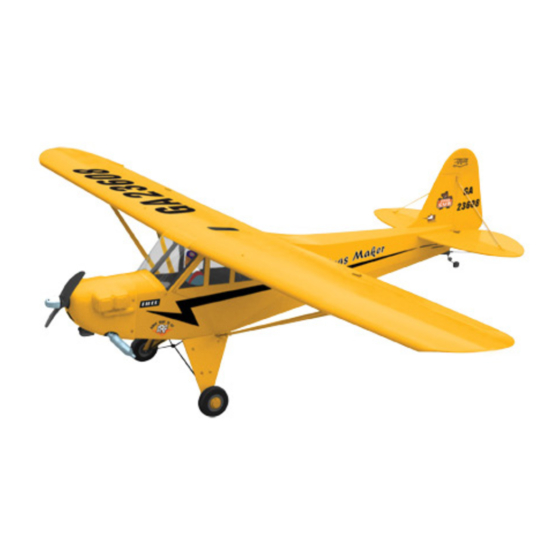
Wing Span: 48.5 in / 1230 mm
Wing Area: 330 sq in / 21.3 sq dm
Flying Weight: 26 oz / 740 g
Fuselage Length: 30.5 in / 760 mm
Requires : Speed 400 motor, 4- channel radio
Warning ! This model is not a toy.
It is designed for maximum performance. Please seek advice if one is not familiar with this kind
of electric powered precision model. Operating this model without prior preparation may cause
injuries. Remember, safety is the most important thing. Always keep this instruction manual at
hand for quick reference.
* Specifications are subject to change without notice.*
THE WINGS MAKER
FACTORY PRE-FABRICATED
ALMOST-READY-TO-FLY (ARF) SERIES
MADE IN CHINA
www. thewingsmaker. com
Specifications
Specifications
w/ 4 micro servos, 15A speed controller
and 7- 8 cells 1000 mAh battery
INSTRUCTION MANUAL
GE016
Advertisement
Table of Contents

Related Manuals for The Wings Maker Piper J-3 Cub EP


Summary of Contents for The Wings Maker Piper J-3 Cub EP
-
Page 1: Instruction Manual
Operating this model without prior preparation may cause injuries. Remember, safety is the most important thing. Always keep this instruction manual at hand for quick reference. * Specifications are subject to change without notice.* THE WINGS MAKER FACTORY PRE-FABRICATED ALMOST-READY-TO-FLY (ARF) SERIES MADE IN CHINA www. - Page 2 I N D E X BEFORE YOU BEGIN P. 1 PARTS LIST P. 2 ASSEMBLY P.3-P.10 SAFETY PRECAUTIONS P. 10 BEFORE YOU BEGIN Read through the manual before you begin, so you will have an overall idea of what to do. Check all parts.
- Page 3 Parts List 1. MAIN WING -- 1 pair 10. WIND SHIELD & SIDE WINDOWS -- 1 set SCREW PWA2x8mm -- 4 pcs 2. PUSHROD Ø1.4x70mm w/ Threads (For Aileron) -- 2 pcs HORN -- 2 sets 11. SPONGE 10x50x150mm -- 1 pc. CLEVIS -- 2 pcs DOUBLE-SIDED TAPE 30x35mm --1 pc.
-
Page 4: Aileron Servo
Main Wing Aileron Servo lead Bottom View Apply instant type CA glue to both sides of each hinge. Ø1mm pilot holes for The Wings Maker tri-horn are pre-drilled. Please Aileron Servo look for pin-hole marks at under side of control surfaces. Straper Screw PM2x18mm... - Page 5 Stabilizer & Elevator (Stabilizer) Temporary install the main wing, adjust leveling of the stabilizer to make it as (Main Wing) Screw parallel to the main wing as possible. PM2x8mm B B' *Also refer to step 15 Wing Setting Completed Ø1mm pilot holes for Wings Maker tri-horn are pre-drilled. PM2x8mm Please lood for pin-hole marks at under side of control surfaces.
-
Page 6: Elevator Pushrod
Elevator Pushrod Pushrod Ø1.4x415mm Bottom View Rudder Pushrod PM2 x 8mm Screw Ø1mm pilot holes for The Wings Maker tri-horn are pre-drilled. Please look for pin-hole marks at side of control surfaces. Pushrod Ø1.4x420mm Clevis Horn Fuel Tube d2xD4x4mm PM2 x 8mm... - Page 7 Motor / Cowling Setting Socket Head Screw M2.6 x 7mm M2.6 x 7mm Screw PM2 x 12mm Screw PM2 x 10mm Screw PWA2 x 8mm Screw PA2.6 x 8mm Speed 400 Motor Gear Box Set Screw Washer d2 x D5mm M2 Nut Washer PM2 x 12mm...
-
Page 8: Radio Equipment
Canopy Screw PWA2 X 8mm 1.5mm PWA2 X 8mm Radio Equipment Rudder Pushrod Battery 15A Speed Controller Battery Tie Ø1.4x420mm Rudder Servo Straper Elevator Pushrod Elevator Servo Double-Sided Tape Ø1.4x415mm Fuel Tube Receiver wrapped up in sponge d2xD4x4mm... -
Page 9: Main Landing Gear
Main Landing Gear Front Screw PA2.6x10mm PVC PLATE Collar PA2.6x10mm 2.6mm M2 NUT 1.5mm PM2x6mm Screw d2xD5mm Washer Wheel Ø50mm 2.6mm collar M2 NUT Washer d2xD5mm 3mm set screw PM2x6mm 20x70mm TRANSPARENT DECALS Main Wing PM2.5x25mm Screw d2.6xD7mm Washer Wing Protection d2.6xD7mm PM2.5x25mm Wing Struts... - Page 10 Wing Setting Adjust the wing and fuselage configuration as shown in the diagrams. A =A ' B =B ' C =C '...
-
Page 11: Control Throws
Adjust the control throws as shown in the Control Throws diagram. These throws are good for general flying. You can adjust according to your personal preference. Rudder 25mm 25mm Elevator 15mm 15mm Aileron 10mm 10mm The ideal C.G. position is 50mm (2.0 in.) behind the leading edge C.G. - Page 12 THE WINGS MAKER GE0160708...
Need help?
Do you have a question about the Piper J-3 Cub EP and is the answer not in the manual?
Questions and answers