Table of Contents
Advertisement
Quick Links
Before commencing assembly, please read these instructions thoroughly.
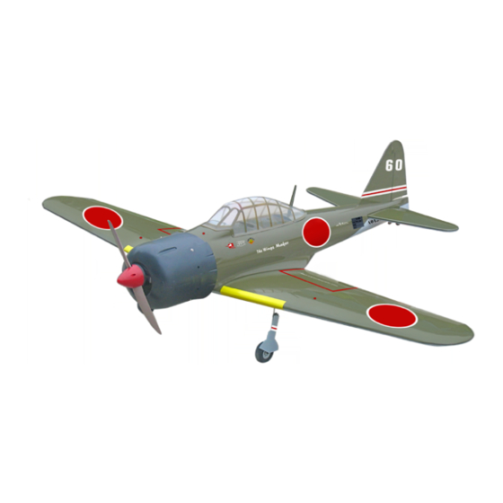
ZERO FIGHTER 60
Wing Span: 60.0 in / 1520 mm
Wing Area: 635 sq in / 41.0 sq dm
Flying Weight: 7.5 Ibs / 3400 g
Fuselage Length: 45.5 in / 1150 mm
Required : 2-stroke 0.61 engine
Warning ! This model is not a toy.
It is designed for maximum performance. Please seek advice if one is not familiar with this kind
of engine powered precision model. Operating this model without prior preparation may cause
injuries. Remember, safety is the most important thing. Always keep this instruction manual at
hand for quick reference.
* Specifications are subject to change without notice.*
THE WINGS MAKER
FACTORY PRE-FABRICATED
ALMOST-READY-TO-FLY (ARF) SERIES
MADE IN CHINA
www.thewingsmaker.com
Specifications
Specifications
6-channel radio w/ 7 servos
INSTRUCTION MANUAL
GA015
Advertisement
Table of Contents

Related Manuals for The Wings Maker ZERO FIGHTER 60


Summary of Contents for The Wings Maker ZERO FIGHTER 60
- Page 1 INSTRUCTION MANUAL Before commencing assembly, please read these instructions thoroughly. ZERO FIGHTER 60 Specifications Specifications Wing Span: 60.0 in / 1520 mm Wing Area: 635 sq in / 41.0 sq dm Flying Weight: 7.5 Ibs / 3400 g Fuselage Length: 45.5 in / 1150 mm Required : 2-stroke 0.61 engine...
-
Page 2: Before You Begin
ZERO FIGHTER 60 I N D E X BEFORE YOU BEGIN P. 1 P. 2 PARTS LIST ASSEMBLY P.3-10 SAFETY PRECAUTIONS P.11 BEFORE YOU BEGIN Read through the manual before you begin, so you will have an overall idea of what to do. - Page 3 Parts List 1. MAIN WING -- 1 pair 13. COWLING --1 pc. TRANSPARENT DUMMY COWLING -- 1 pc. 2. RETRACTABLE LANDING GEAR -- 1 set SCREW PA3x12mm -- 4 pcs SCREW KA3x14mm -- 8 pcs SCREW PM3x8mm -- 4 pcs RIGHT ANGLE WHEEL SPACER -- 2 sets WASHER d3xD7mm -- 8 pcs COLLAR 4.1mm w/ Set Screw -- 2 sets...
-
Page 4: Aileron Servo
Main Wing Peel off shaded portion covering film Aileron Servo Lead Pre-glued Bottom View 3mm Set Screw Retractable Langing Gear Set Screw KA3 x14mm Collar 4.1mm Screw KA3 x14mm Bottom View Aileron Servo PWA2 x12mm Screw Balsa Wood PWA2 x12mm 8 x 18 x 21mm Aileron Servo Cover 2 x 58 x 71mm... - Page 5 Ø1mm pilot holes for The Wings Maker tri-horn are pre-drilled. Aileron Servo Please look for pin-hole marks at under side of control surfaces. PM2 x 12mm PM2 x 16mm PM2 x 16mm Screw PM2 x 12mm Fuel Tube Screw PM2 x 16mm...
- Page 6 Flap Servo Plywood 2x8x20mm Ring Ф2.3mm Peel off shaded portion covering film. 1.5mm Straper Fuel Tube 6 x 5mm -- 3 pcs Clevis Ring Stabilizer/ Elevator A = A' (Stabilizer) (Main Wing) B=B' Temporary install the main wing, adjust leveling of the stabilizer to make it as parallel to the main wing as possible.
-
Page 7: Engine Mount
Vertical Fin / Rudder Pre-glued Screw PA3 x 12mm Set Screw C = C' Collar 2.1mm 3mm Set Screw 3mm Set Screw PA3x12mm Fuel Tank Install Balsa 10 x 10 x 113mm (For fixing fuel tank) Fuel Tank Bottom View Fuel Tank 380cc Engine Mount Screw... - Page 8 Install Engine position Engine Spinner 62mm Screw PM4 x 30mm Fire Wall Throttle Pushwire Washer d4xD9mm w/ plastic tube 115mm 4.53 in. PM4 x 30mm Illustration is for side mounting. You can mount the engine upright or inverted simply by rotating the engine mount.
-
Page 9: Rudder Pushrod
Ø1mm pilot holes for The Wings Maker tri-horn are pre-drilled. Rudder Pushrod Please look for pin-hole marks at side of control surfaces. Screw PM2 x 12mm Fuel Tube Peel off shaded portion Rudder covering film. Tri-horn Tri-horn PM2 x12mm 3 x 14mm Ø1mm pilot holes for The Wings Maker tri-horn are pre-drilled. -
Page 10: Radio Equipment
Radio Equipment Fix the throttle servo tray either to the right or left side of the fuselage according to your throttle pushrod Included with the Radio Set. location. Plywood 3 x 44 x121mm Plywood 6 x60 x119mm Balsa 7 x 7 x 40mm Elevator Servo Bottom View Install Sponge for inserting Battery and Receiver. - Page 11 Wing Setting Adjust the wing and fuselage configuration as shown in the diagrams. A = A' B = B' C = C' Control Trows Adjust the control throws as shown in the diagram. These throws are good for Elevator general flying. You can adjust according 25mm 25mm to your personal preference.
- Page 12 # First time flyer should never fly by himself / herself. Assistance from experienced flyer is absolutely necessary. # Pre-flight adjustment must be done before flying, it is very dangerous to fly a badly pre-adjusted aircraft. ZERO FIGHTER 60 2C 0.61 is specially designed to be powered by engine, using a more powerful engine does not mean better performance.
Need help?
Do you have a question about the ZERO FIGHTER 60 and is the answer not in the manual?
Questions and answers