Table of Contents
Advertisement
Quick Links
Before commencing assembly, please read these instructions thoroughly.
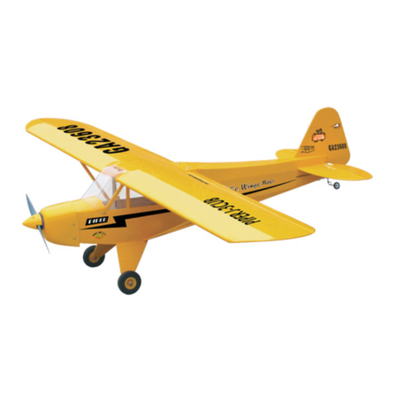
Wing Span: 51.0 in / 1300mm
Wing Area: 419 sq in / 27.0 sq dm
Flying Weight: 3.3-4.0 lbs / 1.5-1.8 kg
Fuselage Length: 33.0 in / 840 mm
Requires: 2-stroke 0.25 or 4-stroke 0.30 engine
Warning ! This model is not a toy.
It is designed for maximum performance. Please seek advice if one is not familiar with this kind
of engine powered precision model. Operating this model without prior preparation may cause
injuries. Remember, safety is the most important thing. Always keep this instruction manual at
hand for quick reference.
* Specifications are subject to change without notice.*
THE WINGS MAKER
FACTORY PRE-FABRICATED
ALMOST-READY-TO-FLY (ARF) SERIES
MADE IN CHINA
www.thewingsmaker. com
Specifications
Specifications
4-channel radio w/ 4 servos
INSTRUCTION MANUAL
GA022
Advertisement
Table of Contents

Related Manuals for The Wings Maker Piper J-3 CUB 26


Summary of Contents for The Wings Maker Piper J-3 CUB 26
-
Page 1: Instruction Manual
Operating this model without prior preparation may cause injuries. Remember, safety is the most important thing. Always keep this instruction manual at hand for quick reference. * Specifications are subject to change without notice.* THE WINGS MAKER FACTORY PRE-FABRICATED ALMOST-READY-TO-FLY (ARF) SERIES MADE IN CHINA www.thewingsmaker. -
Page 2: Before You Begin
I N D E X BEFORE YOU BEGIN P. 1 PARTS LIST P. 2 ASSEMBLY P. 3 - 10 SAFETY PRECAUTIONS P. 10 BEFORE YOU BEGIN Read through the manual before you begin, so you will have an overall idea of what to do. Check all parts. -
Page 3: Parts List
Parts List COVERING: LIGHTEX SGX311 CUB YELLOW... -
Page 4: Engine Mount
Engine Mount PM3x18mm Screw 3.8mm Engine Mount d3xD7mm Washer Fuel Tank Install Basla 8x8x78mm (For fixing fuel tank) Engine PM3x25mm Screw d3xD7mm Washer M3 Nut d3xD7mm M3 Nut 3.5mm PM3x25mm d3xD7mm M3 Nut... -
Page 5: Landing Gear
Landing Gear PM3x16mm Screw d3xD7mm Washer M3 Nut M3 Nut d3xD7mm Washer PM3x16mm 3.5mm Landing Gear PA3x10mm PA3x10mm Screw Landing Gear Wood U-Type 3mm Set Screw 6x10x13mm 3.1mm Collar Balsa 2x90x80mm... - Page 6 Canopy Securely glue the windows to the fuselage. PWA2.3x8mm Screw 1.5mm PWA2.3x8mm Cowling Trim the cowling for the engine head to project PWA2.6x12mm Screw 2.5mm 1.5mm d1.5xD6.5mm Silicon Grommet Strengthen the in side of the fuselage with pieces cut to appropriate sizes from the transparent plastic sheet.
-
Page 7: Aileron Servo
Straper Aileron Servo Fuel Tube 5x8x20 Ø6x5mm Balsa 5x8x20 Balsa Ø1.8x80mm Clevis Ring Vertical Fin / Stabilizer (Stabilizer) (Main Wing) A=A' Temporary install the main wing, adjust leveling of the stabilizer to make it as parallel to the main wing as possible. 90°... - Page 8 Linkage Connector 3mm Set Screw Included with the radio set. Linkage Stopper Throttle Rod Included with the radio set. M2 Nut 2mmWasher Throttle Servo Rudder Rod Heat-shrink Tube Fuel Tube Ø1.8x160mm Ø1.8x120mm Fuel Tube Mind the flame. Lighter Rudder Servo Be careful not to scorch Completed Wooden Rod...
-
Page 9: Radio Equipment
Install and arrange the servos as shown in the diagram. Radio Equipment Balsa x8x78mm Throttle Servo Receiver Fuel Tank Elevator Servo Battery Rudder Servo Radio Equipment Front Elevator Pushrod Rudder Pushrod Throttle Rod Make both pushrods exit as shown in the diagram. Linkage Elevator Pushrod &... -
Page 10: Wing Struts
Wing Struts 362mm 71mm PA2.6x12mm Screw 90mm PA2.6x12mm Main Wing / Wing Struts PM3x30mm PM3x30mm Screw d3xD12mm Washer Transparent Plastic Sheet d3xD12mm Washer 3mm Washer M3 Nut PM3x10mm M3 Nut In order to obtain the wing and fuselage configuration as in the Wing Setting diagrams, insert plates between the wing and fuselage. -
Page 11: Control Throws
Control Throws Adjust the control throws as shown in the diagram. These throws are good for general flying. You can adjust according to your Elevator 14mm personal preference. 14mm Rudder 28mm 28mm Aileron C.G. The ideal C.G. position is 65mm (2.56 in) behind the leading edge measured at where the wing meets the fuselage. - Page 12 THE WINGS MAKER GA0220704...
Need help?
Do you have a question about the Piper J-3 CUB 26 and is the answer not in the manual?
Questions and answers