Table of Contents
Advertisement
Advertisement
Table of Contents

Related Manuals for Grizzly VS MILLING MACHINE G0669X


Summary of Contents for Grizzly VS MILLING MACHINE G0669X
- Page 1 HIGH-PRECISION 10" X 54" VS MILLING MACHINE OWNER'S MANuAL Copyright © JULy, 2008 By grizzLy indUstriaL, inC. WARNING: NO PORtION Of tHIS MANuAL MAy bE REPRODuCED IN ANy SHAPE OR fORM WItHOut tHE WRIttEN APPROVAL Of GRIzzLy INDuStRIAL, INC. #ts10556 printed in taiWan...
-
Page 3: Table Of Contents
INtRODuCtION ... 2 Foreword ... 2 Contact info... 2 Functional overview ... 2 identification ... 3 Machine data sheet ... 6 SECtION 1: SAfEty ... 9 safety instructions for Machinery ... 9 additional safety instructions For Mills ... 11 SECtION 2: CIRCuIt REQuIREMENtS ... 12 220V single-phase operation ... -
Page 4: Introduction
We are proud to offer the Model g0669X high- precision 10" x 54" Milling Machine. this machine is part of a growing grizzly family of fine machin- ery. When used according to the guidelines set forth in this manual, you can expect years of trouble-free, enjoyable operation and proof of grizzly’s commitment to customer satisfaction. -
Page 5: Identification
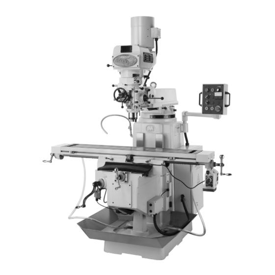
A. turret b. ram C. Lifting eye Bolt D. spindle Motor 5 hp 220V 3-phase E. drive system emergency spindle Brake G. Quill speed selector H. Quill spindle table K. Longitudinal (X-axis) Ball handle g0669X precision 10" x 54" Vs Milling Machine Identification figure 1. - Page 6 A. Quill auto-downfeed Controls (see Page 31 for more detail) b. Quill auto-downfeed selector C. Control panel (see Page 24 for more detail) D. Longitudinal power Feed Limit switch E. table Lock Longitudinal Ball handle G. Longitudinal power Feed figure 2. Front identification. H.
- Page 7 A. spindle Motor Wiring Junction Box b. drive system Cooling Fan C. ram Movement Controls D. Main power switch (on back of electrical Cabinet) E. electrical Cabinet auxiliary 110V outlets (on back of electrical Cabinet) g0669X precision 10" x 54" Vs Milling Machine figure 3.
-
Page 8: Machine Data Sheet
Machine Data Sheet MODEL G0669X EXTREME SERIES 10" X 54" VARIABLE-SPEED VERTICAL MILLING MACHINE Product Dimensions: Shipping Dimensions: Electrical: Motors: Spindle Motor Coolant Pump Motor MACHINE DATA SHEET w/POWER FEED machine data sheet g0669X precision 10" x 54" Vs Milling Machine... - Page 9 Longitudinal Power Feed Motor Table Elevation Motor Main Specifications: Table Information Operation Information g0669X precision 10" x 54" Vs Milling Machine...
- Page 10 Spindle Information Construction Information Other Specifications Features: g0669X precision 10" x 54" Vs Milling Machine...
-
Page 11: Section 1: Safety
Safety Instructions for Machinery g0669X precision 10" x 54" Vs Milling Machine... - Page 12 -10- g0669X precision 10" x 54" Vs Milling Machine...
-
Page 13: Additional Safety Instructions For Mills
Additional Safety Instructions for Mills 1. uNDERStANDING CONtROLS. Make sure you understand the use and operation of all controls. SAfEty ACCESSORIES. always use a chip guard in addition to your safety glasses or use a face shield when milling to reduce the risk of injury from flying chips. -
Page 14: Section 2: Circuit Requirements
SECtION 2: CIRCuIt REQuIREMENtS 220V Single-Phase Operation Serious personal injury could occur if you connect the machine to power before com- pleting the setup process. DO NOt connect the machine to the power until instructed later in this manual. Electrocution or fire could result if machine is not grounded and installed in compliance with electrical... -
Page 15: Section 3: Setup
SECtION 3: SEtuP Setup Safety this machine presents serious injury hazards to untrained users. Read through this entire manu- al to become familiar with the controls and opera- tions before starting the machine! Wear safety glasses dur- ing the entire setup pro- cess! the Model G0669X is a heavy machine. -
Page 16: Inventory
Inventory the following is a description of the main compo- nents shipped with your machine. Lay the compo- nents out to inventory them. Note: If you can't find an item on this list, check the mounting location on the machine or examine the packaging materials carefully. -
Page 17: Clean Up
G2544—Solvent Cleaner & Degreaser a great product for removing the waxy shipping grease from your machine during clean up. figure 7. Cleaner/degreaser available from grizzly. g0669X precision 10" x 54" Vs Milling Machine Site Considerations floor Load refer to the Machine Data Sheet on Page 6 for the weight and footprint specifications of your machine. -
Page 18: Moving & Placing Base Unit
Moving & Placing base unit the Model G0669X is a heavy machine. Serious personal injury may occur if safe moving methods are not used. to be safe, get assistance and use power equipment to move the shipping crate and remove the machine from the crate. -
Page 19: Mounting To Shop Floor
position the lifting straps under the ram, as shown in figure 10, with padding between the straps and the mill to protect the ram way. Lift the mill slowly to make sure the hook and lifting straps are secure and the mill is lifting evenly. -
Page 20: Assembly
Assembly tools Needed ... Qty snap ring pliers ... 1 hex Wrench 4mm ... 1 Wrench 14mm ... 1 phillips screwdriver ... 1 standard screwdriver ... 1 to assemble the mill: Move the head to an upright position (refer to Head Movement on Page 27 for detailed instructions). - Page 21 slide the fine downfeed handwheel onto the shaft on the front of the head, as shown in figure 15. Fine downfeed handwheel figure 15. Fine downfeed handle installed. slip the coarse downfeed handle onto the shaft located on the right side of the head, as shown in figure 16.
-
Page 22: Test Run
10. Use the cross feed ball handle to move the table back to the column until you can posi- tion the front way cover on the saddle ways, then secure the cover in place with the five screws shown in figure 19. screws figure 19. - Page 23 to test run the machine: Make sure you understand the safety instruc- tions at the beginning of the manual and that the machine is setup properly. Make sure all tools and objects used during setup are cleared away from the machine. Lubricate the mill, as explained in Lubrication on Page 38.
- Page 24 10. Verify that the machine is operating cor- rectly. —When operating correctly, the machine runs smoothly with little or no vibration or rubbing noises. — investigate and correct strange or unusual noises or vibrations before operating the machine further. always stop the machine and disconnect it from power before inves- tigating or correcting potential problems.
-
Page 25: Spindle Break-In
16. start spindle rotation. 17. test the variable speed dial by turning the speed all the way up for a few seconds, then turning it all the way down. 18. point the coolant nozzle onto the table, turn the coolant pump switch to "l" or ON, then check for proper operation of the coolant sys- tem. -
Page 26: Section 4: Operations
OMMEND that you read books, trade maga- zines, or get formal training before begin- ning any projects. Regardless of the con- tent in this section, Grizzly Industrial will not be held liable for accidents caused by lack of training. -24-... -
Page 27: Table Movement
E. Spindle Speed Readout: displays the spin- dle speed in rpM's—the top numbers are for the high speed range, and the bottom num- bers are for the low speed range. Coolant Pump Switch: turns the coolant pump on/oFF. G. Vertical Power feed Down button: Lowers the knee. - Page 28 Longitudinal Power feed System your mill is equipped with a longitudinal power feed and limit switch for controlled X-axis table movement. refer to figure 27 and the descrip- tions below to understand the functions of these devices. figure 27. Longitudinal power feed system. A.
-
Page 29: Head Movement
rotate the speed dial all the way to the left, then use the direction lever to select the direction of table travel. Flip the on/oFF switch up to turn the power feed ON. adjust the speed dial to move the table at the correct speed for your operation. -
Page 30: Ram Movement
Rotating the Head disConneCt the MiLL FroM poWer! Loosen the four rotation locking bolts shown in figure 32. Locking Bolts figure 32. head rotation bolts. With one hand helping to support the weight of the head, slowly turn the rotation bolt. Note: Turn the rotation bolt clockwise to move the head to the right and counterclock- wise to move it to the left. -
Page 31: Setting Spindle Rpm
Rotating the Ram disConneCt the MiLL FroM poWer! Loosen the four rotation locking bolts on top of the column shown in figure 34. Locking Bolts figure 34. ram rotation locking bolts. Manually rotate the ram around the column to the desired position. Note: Take care not to entangle or stretch the electrical cabling as you move the ram and head. - Page 32 Measure the diameter of your cutting tool in inches. Use the following formula to calculate the required rpM for your operation: Selecting Spindle Speed Range Make sure the spindle motor is turned OFF, and the spindle is stopped. select the range in the chart below that includes the spindle speed that you have cal- culated for your workpiece.
-
Page 33: Downfeed Controls
Downfeed Controls the quill downfeed movement is controlled by three mechanisms: 1) the coarse downfeed handle, 2) the fine downfeed handwheel, and 3) the quill auto-downfeed system. Coarse Downfeed Handle turn the spindle motor OFF and wait for the spindle to stop. pull the quill auto-downfeed selector knob out and rotate it clockwise to the disengage (forward) position (see figure 38). - Page 34 fine & Auto-Downfeed Components there are a number of devices that are used for fine downfeed and quill auto-downfeed control. Use figure 40 and the descriptions below to understand the functions of these devices. figure 40. Fine downfeed and quill auto- downfeed system components.
-
Page 35: Emergency Spindle Brake
push or pull the auto-downfeed direction pin to select the desired direction of quill move- ment. NOTICE When the spindle speed range is changed, the rotation direction of the spindle will reverse and so will the direction of the quill when in auto-downfeed mode. -
Page 36: Loading/Unloading Tooling
Loading/unloading tooling your mill is equipped with a drawbar that includes one spacer for tool attach- ment flexibility (see figure 42). spacer figure 42. drawbar and spacer. tools Needed Wrench 19mm ... 1 Loading tooling disConneCt the MiLL FroM poWer! Clean any debris or oily substances from the mating surfaces of the spindle and tool tapers. -
Page 37: Section 5: Accessories
aCCessories SECtION 5: ACCESSORIES H6089—2 Axis Digital Read Out (12" x 30") H6093—3 Axis Digital Read Out (12" x 30" x 5") H7850—3 Axis Digital Read Out (12" x 30" x 16 ⁄ ") you will be amazed the list of features for these dros that include: selectable resolution down to 5µm, absolute/incremental coordinate display, arc function, line of holes function, angled cuts func-... - Page 38 10 second vernier scales, gear drives with oil immersion and satin chrome dials. see the current grizzly catalog for full specifica- tions. Features: 4.330" overall height (horizontal), 6.750" height to center hole (vertical), #3 Morse taper, 0.465"...
-
Page 39: Section 6: Maintenance
SECtION 6: MAINtENANCE Always disconnect power to the machine before performing maintenance. failure to do this may result in serious person- al injury. Schedule For optimum performance from your machine, follow this maintenance schedule and refer to any specific instructions given in this section. before Daily Operation: •... -
Page 40: Lubrication
Lubrication your mill has numerous moving metal-to-metal contacts that require proper lubrication to help ensure efficient and long-lasting mill operation. other than lubrication points covered in this sec- tion, all other bearings are internally lubricated and sealed at the factory. simply leave them alone unless they need to be replaced. - Page 41 Ram Way Lubricant frequency iso 68 sae 20W every Bearing and gear 40 hours Lubricant of operation Move the ram forward and backward as neces- sary to access the entire length of the ram way (see figure 55). Use mineral spirits and shop rag to wipe the old lubricant and debris from the way surfaces, then brush on a thin coat of lubricant.
-
Page 42: Coolant Reservoir
Coolant Reservoir Coolant is a potent and extremely solution to humans and animals. use personal protective when handling coolant to prevent infections or poisoning. a small amount of coolant is lost during normal operation. Check the coolant reservoir regularly and fill it if necessary. Checking/Adding Coolant tools Needed phillips screwdriver ... -
Page 43: Changing Coolant
Changing Coolant the Model g0669X coolant reservoir holds approximately 7 gallons (26 liters) of fluid. We rec- ommend changing this fluid every three months or sooner if it develops an unpleasant odor. tools Needed phillips screwdriver ... 1 hex Wrench 5mm ... 1 Catch pan ... -
Page 44: Drive Belt Tensioning
Drive belt tensioning power is transferred from the motor to the spindle with a heavy-duty drive belt. With normal use, this belt will gradually stretch over time. When it does, perform the following procedures to re-tension it. tools Needed phillips screwdriver ... 1 Wrench 13mm ... -
Page 45: Section 7: Service
SECtION 7: SERVICE review the troubleshooting and procedures in this section to fix or adjust your machine if a problem devel- ops. if you need replacement parts or you are unsure of your repair skills, then feel free to call our technical support at (570) 546-9663. - Page 46 Motor & Electrical (continued) symptom possible Cause Machine stalls or is 11. Contactor not getting energized or has poor overloaded. contacts. 12. Motor has overheated. 13. spindle rotation switch at fault. 14. Motor is at fault. 15. Frequency drive at fault. Machine 1.
-
Page 47: Operation
Operation symptom possible Cause tool slips in collet. 1. Collet is not fully drawn into spindle taper. 2. Wrong size collet. 3. debris on collet or spindle mating surface. 4. excessive depth of cut. Breaking tooling. 1. spindle speed/feed rate too fast. 2. -
Page 48: Adjusting Gibs
Adjusting Gibs gibs control the accuracy of table and ram move- ments along the ways. tight gibs make the move- ments more accurate, but harder to move. Loose gibs make the movements sloppy, but easier to move. the goal of gib adjustment is to remove unnecessary sloppiness without causing the ways to bind. -
Page 49: Adjusting Backlash
Adjusting backlash Leadscrew backlash is the amount of motion the leadscrew rotates before the device begins to move. Leadscrews always have a certain amount of backlash that will increase with wear. generally, 0.005"–0.010" of backlash is acceptable. tools Needed t-handle hex Wrench 5mm ... 1 hex Wrench 8mm ... - Page 50 Use the t-handle 5mm hex wrench to loosen the two cap screws shown in figure 67. adjustment plate Cap screws figure 67. Cross feed leadscrew backlash adjustment plate and cap screws. rotate the adjustment plate in small incre- ments, then test the backlash. Note: To test the backlash, re-install the key and ball handle onto the leadscrew.
-
Page 51: Section 8: Electrical
(570) 546-9663. NOTICE the photos and diagrams included in this section are best viewed in color. you can view these pages in color at www.grizzly.com. POWER. this -49-... -
Page 52: Electrical Panel
resistor Frequency drive transformer Contactors Motor overload relay to Knee Wiring Junction terminal Blocks -50- READ ELECTRICAL SAFETY ON PAGE 49! Electrical Panel figure 69. electrical panel wiring. g0669X precision 10" x 54" Vs Milling Machine to Control panel Main power switch Cooling... - Page 53 electrical panel upper Electrical Panel Wiring Diagram (upper) to Control panel (Page 54) -51- READ ELECTRICAL SAFETY g0669X precision 10" x 54" Vs Milling Machine ON PAGE 49!
- Page 54 electrical panel lower Electrical Panel Wiring Diagram (Lower) to spindle Motor (Page 55) to Control panel (Page 54) -52- READ ELECTRICAL SAFETY ON PAGE 49! g0669X precision 10" x 54" Vs Milling Machine to power supply (Page 57) to Knee Wiring Junction Box (Page 56) to Coolant...
-
Page 55: Control Panel
Control Panel spindle spindle Motor speed spindle Motor on Button dial oFF Button spindle speed spindle readout direction switch Coolant pump switch Vertical power Feed Vertical power Feed emergency stop Up Button down Button Button figure 70. Control panel wiring. -53- READ ELECTRICAL SAFETY g0669X precision 10"... -
Page 56: Control Panel Wiring Diagram
control panel wiring Control Panel Wiring Diagram – -54- READ ELECTRICAL SAFETY g0669X precision 10" x 54" Vs Milling Machine ON PAGE 49! -
Page 57: Spindle Motor
motor wiring Spindle & Vertical Power feed Motors Spindle Motor figure 71. spindle motor wiring junction box. to electrical to drive system panel Cooling Fan (Page 51) (Page 57) to emergency spindle Brake (Page 57) Vertical Power feed Motor to Knee Wiring Junction (Page 56) -
Page 58: Electrical Components
electrical components 1 wiring Electrical Components Knee Wiring Junction box to Vertical power to Vertical Crank Feed Motor safety switch (Page 55) (this page) Vertical Crank Safety Switch to Knee Wiring Junction Box (this page) Vertical Limit Switches to Knee Wiring Junction Box (this page) -56-... -
Page 59: Emergency Spindle Brake Safety Switch
electrical components 2 wiring Electrical Components Coolant Pump to electrical panel (Page 52) figure 76. Coolant pump wiring. Drive System Cooling fan to spindle Motor Wiring Junction Box (Page 55) figure 77. drive system cooling fan wiring. Emergency Spindle brake Safety Switch to spindle Motor Wiring Junction Box... -
Page 60: Section 9: Parts
SECtION 9: PARtS base Machine breakdown -58- g0669X precision 10" x 54" Vs Milling Machine... - Page 61 base Machine Parts List REF PART # DESCRIPTION P0669X001 WORM WASHER P0669X002 RAM ADAPTER P0669X003 ADAPTER SCALE P0669X004 LOCK BOLT HEX NUT P0669X006 WORM P0669X007 COLLAR P0669X008 WORM SHAFT PK36M KEY 5 X 5 X 50 P0669X010 P0669X011 LIFTING EYE BOLT 3/4-10 P0669X012 SPACER PSB13M...
- Page 62 base Machine Parts List REF PART # DESCRIPTION P0669X141 BEVEL GEAR 18T P0669X142 SPACER P0669X143 SPANNER NUT P0669X144 SPANNER LOCK WASHER P6204 BALL BEARING 6204ZZ P0669X146 BEARING BRACKET PSB14M CAP SCREW M8-1.25 X 20 P6206 BALL BEARING 6206ZZ PK48M KEY 4 X 4 X 20 P0669X150 DRIVE SHAFT PK34M...
-
Page 63: Drive System
Drive System breakdown -61- g0669X precision 10" x 54" Vs Milling Machine... - Page 64 Drive System Parts List REF PART # DESCRIPTION P0669X201 LOWER PULLEY HOUSING PSB02M CAP SCREW M6-1 X 20 P0669X203 GEAR SHAFT PINION P0669X204 DETENT PLATE P0669X205 DETENT PLUNGER P0669X206 COMPRESSION SPRING PSB20M CAP SCREW M5-.8 X 14 P0669X208 PINION BLOCK P0669X209 PINION CRANK P0669X210...
-
Page 65: Head Breakdown
Head breakdown -63- g0669X precision 10" x 54" Vs Milling Machine... -
Page 66: Head Parts List
REF PART # DESCRIPTION PSB26M CAP SCREW M6-1 X 12 PW03M FLAT WASHER 6MM P0669X303 FEED BEVEL PINION P0669X304 GEAR SHAFT SLEEVE P0669X305 LOCK COLLAR PSS02M SET SCREW M6-1 X 6 P0669X308 FEED GEAR 20T PK103M KEY 3 X 3 X 12 PSB11M CAP SCREW M8-1.25 X 16 PW01M... - Page 67 REF PART # DESCRIPTION P0669X437 BUSHING P0669X435 ANGULAR BEARING 7207C PSS07M SET SCREW M5-.8 X 5 P0669X443 BUSHING PSS02M SET SCREW M6-1 X 6 P0669X442 QUILL PRP02M ROLL PIN 3 X 16 P0669X445 TRIP LEVER P0669X446 TRIP LEVER PIN P0669X447 INDICATOR ROD P0669X448 QUILL INNER LOCK PLUNGER...
-
Page 68: Longitudinal & Cross Slide Leadscrews
Longitudinal & Cross Slide Leadscrews breakdown & Parts List REF PART # DESCRIPTION PN01 HEX NUT 1/2-20 P0669X502 HANDLE P0669X503 BALL CRANK P0669X504 DIAL LOCK RING P0669X505 GRADUATED DIAL P0669X506 DIAL HOLDER PSB26M CAP SCREW M6-1 X 12 P0669X508 BEARING CAP P6204 BALL BEARING 6204ZZ P0669X510... -
Page 69: One-Shot Oiler
One-Shot Oiler breakdown & Parts List REF PART # DESCRIPTION P0669X601 ONE SHOT OILER ASSEMBLY P0669X602 ALUMINUM PIECE 13.5MM P0669X603 OIL REGULATION DISTRIBUTOR P0669X604 OIL REGULATION DISTRIBUTOR P0669X605 FLEXIBLE STEEL TUBE 4 X 550MM P0669X606 ELBOW JOINT P0669X607 ELBOW JOINT Control Panel Electrical Components breakdown &... -
Page 70: Electrical Cabinet
Electrical Cabinet breakdown & Parts List REF PART # DESCRIPTION P0669X801 ELECT CABINET SAFETY SWITCH P0669X802 POWER SWITCH KEDU ZH-HD-2 P0669X803 COOLING FAN P0669X804 FREQ DRIVE YASKAWA VS-606V7 P0669X805 RELAY OMRON MY2-110NJ 805-1 P0669X805-1 RELAY SOCKET OMRON PYF-08A P0669X806 FUSE HOLDER GIKOKA 3P30A600V 806-1 P0669X806-1 FUSE 32A GIN-SING 30A600V P0669X807... -
Page 71: Accessories
Accessories breakdown & Parts List REF PART # DESCRIPTION P0669X901 COOLANT HOSE W/CLAMP P0669X902 TOOL BOX PSDP2 SCREWDRIVER PHILLIPS #2 PSDF2 SCREWDRIVER FLAT #2 P0669X905 HEX WRENCH SET 1.5-10MM g0669X precision 10" x 54" Vs Milling Machine REF PART # DESCRIPTION P0669X906 FREQENCY DRIVE MANUAL... -
Page 72: Label Placement
MuSt maintain the original location and readability of the labels on the machine. If any label is removed or becomes unreadable, REPLACE that label before using the machine again. Contact Grizzly at (800) 523-4777 or www.grizzly.com to order new labels. -70-... -
Page 75: Warranty And Returns
WARRANty AND REtuRNS...
Need help?
Do you have a question about the VS MILLING MACHINE G0669X and is the answer not in the manual?
Questions and answers