Table of Contents
Advertisement
Quick Links
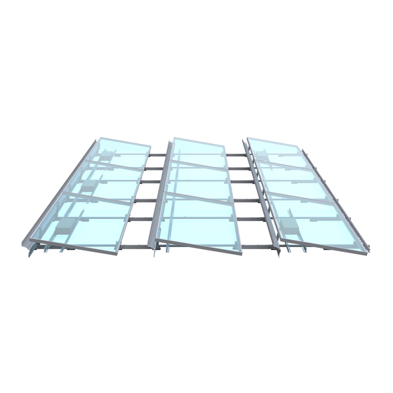
clawFR 10 Degree
Installation Manual
9910045 RevG April 2021
System Fire Class Rating: Class A for low slope roofs with Type 1, 2, 16, 19, 22, 25, 29 and 30 Modules
Scan here for
installation
videos
Table of Contents
O&M considerations
Mechanical Load Rating: See
Appendix A: UL 2703 Grounding
2
3
4
5
6
7
8
9
10
12
14
16
17
18
19
20
21
ANSI/UL 2703
Advertisement
Table of Contents

Related Manuals for ESDEC PANELCLAW clawFR 10 Degree


Summary of Contents for ESDEC PANELCLAW clawFR 10 Degree
-
Page 1: Table Of Contents
Scan here for installation videos Table of Contents Introduction & Safety Overview Storage, Array Construction, and O&M considerations System Components Accessories Tools, Torque, & Construction Aid Construction Aid Setup Build Assemblies Build North Array Row Build Remaining Rows Place Ballast Install Module Low Side clawFR 10 Degree Install Module High Side... -
Page 2: Introduction & Safety Overview
Safety Overview Introduction Safety is an essential part of every PV installation and every The clawFR 10 Degree flat roof mounting system is comprised of construction site. It is imperative to plan ahead for any safety four major components that intuitively assemble into a support concerns and hazards to promote safe work practices during structure for photovoltaic (PV) modules. -
Page 3: Storage, Array Construction, And
Storage Considerations Sub Array Dimensions PanelClaw recommends installing the racking components shortly Each PV system is unique and is frequently made up of multiple after delivery to the project site. If clawFR components are not sub arrays. The Racking Construction Set, which must be onsite at deployed immediately, they should be stored in a well-ventilated, all times during construction, details sub array dimensions and dry location. -
Page 4: System Components
System Components Pair of grooves Base Module Connector Cam Claw* M6x16mm Bolt 2000673 (1 pair of grooves) 5000502XX 5000507XX 5000500 2000697 2000815 (1 groove) Rail Wind Deflector 2000695/2000895 2000887XX Ballast Block: Solid cap concrete roof paver, conforms to ASTM C1491 or C1884 standard and manufactured for freeze-thaw resistance where applicable. -
Page 5: Accessories
Accessories See: Appendices D-H Ground Lug Kit Optimizer Attachment Base Pad Shim Pad 5000494 5000509 2000678 5000228 Mechanical Hardware Kit Mechanical Attachment Strut Lock Claw Clip 500022301/5000423 2000830/2000930 2000819 Note: Use of non-UL listed accessories, including non-metallic components, does not affect the system ANSI/UL 2703 certification. Wire Management Accessories See: 9910053-Wire Management Manual WM Homerun... -
Page 6: Tools, Torque, & Construction Aid
Construction Aids Spacer Stick Cam Spacer / Lock Claw Insertion Depth Gauge Spacer Stick and Cam Spacer Kit 5000510/5000610 2000761 may be required Tools Drill with Inline-Torque Limiter or Torque Wrench 10 mm Magnetic Nut Driver ALERT: NO IMPACT DRIVERS Torque Setting* Fastening Operation Bolts which are installed into a pre-installed nut... -
Page 7: Construction Aid Setup
1. Construction Aid Setup Tip: L, S, and Cam Spacer dimensions are found in the Racking Construction Set. See Sheet Title: Typical Array Dimensions. 1.1 Assemble the Spacer Stick and adjust to L & S dimensions. All dimensions are measured from the Base centerlines. Tip: To stiffen the Spacer Stick, place one Rail 2000695/2000895 on the assembly as shown, shift the Rail Rail 2000695/2000895... -
Page 8: Build Assemblies
2. Build Assemblies Scan here for Assembly Jig Manual Hole 1 Tilt Arm 2.1 Position components as required per assembly type and loosely assemble the Cam, Module Connector and Base. Hole 2 ALERT: Note location of orientation marker on Base “ ” Hole 3 Tip: Base length may vary depending on the row spacing option. -
Page 9: Build North Array Row
Scan here for 3. Build North Row rail installation video ALERT: ensure system alignment, use the Spacer Stick to align Module Connectors before securing Rails Spacer Stick See Sheet Title: Typical Array Tip: L, S, R and AEBE dimensions Dimensions in the Racking are found in the Racking Construction Set for AEBE Construction Set. -
Page 10: Build Remaining Rows
4. Build Remaining Rows Spacer Stick Tip: Raise Tilt Arms after bolting assemblies in preparation for Rail installation. Middle or South Assembly Rail are required at Southern Array Edges 4.2 Install Rails throughout the array using the same steps described on the previous page. Alternating between “S”... - Page 11 Scan here for 4. Build Remaining Rows (Continued) common rail installation mistakes Rail Configurations for South Interior Corners Torque to 3 ft-lb In cases where a contiguous array has module omissions additional Rails must be installed as shown. Rails are installed across the edge to connect row Alert: Modules are included for illustrative purposes only Rails are installed across the...
-
Page 12: Place Ballast
5. Place Ballast Tip: Installing the north row ballast blocks helps keep the racking structure from moving as the rest of the array is built. Tip: Sheet Title: Ballast Layout –XX in the Racking Construction Set identifies where Ballast is to be installed. Mark the roof with chalk to speed up installation. - Page 13 5. Place Ballast (Continued) 5.3 Ballast must be placed as shown. Ballast quantity affects the Ballast placement on the Rails and in some cases additional Rails are required as noted below. Rail 2 *ALERT: Modules longer than 2100 mm with 7 or 8 ballast blocks require two (2) Rails.
-
Page 14: Install Module Low Side
Scan here for 6. Install Module Low Side module installation video ALERT: Install Mechanical Attachments before installing modules. See Appendix D Tip: R dimension is found in the Racking Construction Set. See Sheet Title: Typical Array Cam Seat Dimensions Tip: Installing modules starting at the south array edge provides more working Cam Claw... - Page 15 6. Install Module Low Side (Continued) Cam flanges are located away from the module mounting holes If Cam flanges align with the module mounting holes, Contact PanelClaw. Consult Sheet Title: Typical Array Dimensions in the Racking Construction Set to verify that appropriate R dimension is in use.
-
Page 16: Install Module High Side
Scan here for 7. Install Module High Side module high side installation video Tongue Tilt Arm Lock Claw Tip: Use two hands when engaging Lock Claw to ensure correct installation. Tip: See Appendix I for Lock Claw Support module while carefully Pull the Tilt Arm forward until the Lock Rotate module down and rest the module reset method. -
Page 17: Continue Installing Modules
7. Continue Installing Modules Use Cam Claw as spacer to set spacing between modules. ALERT: Check the R dimension every 5 module and adjust spacing between modules as needed. ALERT: If Cam Flanges are located on Module mounting holes refer to page 15 of the manual to verify appropriate spacing. -
Page 18: Install Deflectors
8. Install Deflectors* ALERT: When forecasted wind gusts exceed 25% of the wind speed listed in the site criteria table of the Racking Construction Set, Deflectors must be installed on all mounted modules to avoid possible system damage. Tip: Adjacent Deflectors will overlap Center Deflector on module (adjacent deflector not shown). -
Page 19: Cam & Lock Claw Inspection
9. Cam & Lock Claw Inspection Cam installation can be quickly visually Inspect Cam side module connection inspected (no gauge is available or required) by comparing a known good installation with all other installations. Some gap between Module and Cam is permissible. -
Page 20: Electrical Grounding
Electrical Grounding Please consult with national and local building code(s) for Grounding Instructions complete grounding requirements for your installation. The clawFR grounding method conforms to ANSI/UL 2703 and is For modules that have been evaluated for use with clawFR 10 Degree, certified by SolarPTL for use with approved photovoltaic please follow the instructions below in Appendix A: UL 2703... -
Page 21: Appendix
Appendix A: UL 2703 Grounding The clawFR 10 Degree flat roof system may be used to ground and/or mount a PV module complying with ANSI/UL 1703 or ANSI/UL 61730 only when the specific module has been evaluated for grounding and/or mounting in compliance with the included instructions. - Page 22 Appendix A: UL 2703 Grounding (Continued) Grounding Instructions: PanelClaw components within the array are required to be electrically bonded to other DC grounding paths via the use of appropriately sized Cu wire and a UL 467 listed Tyco Solarlok grounding assembly, part number 2106831-1, manufactured by Tyco Electronics Corporation.
- Page 23 Appendix B: UL 2703 Fire Classification The system has a Fire Class A rating for low slope roofs with Type 1, 16, 19, 22, 25, 29 and 30 modules when the following requirements are met: • System is installed over a fire resistant roof covering rated for the application (UL2703, 26.3B) •...
- Page 24 Appendix C: Ballast Blocks PanelClaw does not provide the ballast blocks required to construct the system in accordance with PanelClaw’s Racking Construction Set drawings. However, PanelClaw maintains a list of potential block suppliers across the country and this list is available upon request. Ballast blocks for any ballasted rooftop system shall conform to ASTM C1491 or C1884 where applicable.
- Page 25 Appendix D: Mechanical Attachment (“MA") Strut Part Number: 500022301 & 2000830 Tools Required: Drill with In-Line Torque Limiter or torque wrench Various sockets (see table) ALERT: NO IMPACT DRIVERS Torque Setting* Fastening Operation Socket sizes Fastening Operation 21 ft-lb (29 Nm) L-bracket connections (3/8”...
- Page 26 Appendix D (Continued) Part Number: 500022301 & 2000830 Tip: Use off-center slots on the MA Strut if roof obstructions prevent the use of center slot. Step 2. Center Strut assembly between Bases at required install location. With felt marker or other means Mark location of Roof Attachment on the...
- Page 27 Appendix D (Continued) Part Number: 500022301 & 2000830 High Edge Installation Location (Typical) MA Struts may be installed in several possible array M6 Bolts locations. tighten to 6ft-lb ALERT: See Sheet Title: Ballast Layout –XX in the Racking Construction Set for installation locations of Mechanical Attachments on each individual project.
- Page 28 Appendix D (Continued) Part Number: 5000423 & 2000930/2000830 Tools Required: Drill with In-Line Torque Limiter or torque wrench Various sockets (see table) ALERT: NO IMPACT DRIVERS Torque Setting* Fastening Operation Socket sizes Fastening Operation 21 ft-lb (29 Nm) U-bracket connections (3/8” bolts) 10 mm Magnetic Used with 6 mm bolts 6 ft-lb (8.1 Nm)
- Page 29 Appendix D (Continued) Part Number: 5000423 & 2000930/2000830 Step 2. Center Strut assembly between Bases at Tip: Use off-center slots on the required install location. With a felt marker or MA Strut if roof obstructions other means Mark location of Roof Attachment in prevent the use of center slot.
- Page 30 Appendix D (Continued) Part Number: 5000423 & 2000930/2000830 High Edge Installation Location (Typical) MA Struts may be installed in several possible array M6 Bolts locations. tighten to 6ft-lb ALERT: See Sheet Title: Ballast Layout –XX in the Racking Construction Set for installation locations of Mechanical Attachments on each individual project.
- Page 31 Appendix E: Shim Pad Part Number: 5000228 Some roof systems with slope changes and/or localized undulations may result in cases where the Base Pads are more than 2” off the roof after array grid construction (prior to ballast, module, and deflector installation). If this occurs Shim Pads can be provided and installed on the bottom of the Base Pads to ensure the Base rests on the roof at all contact points.
- Page 32 Appendix F: Base Pad Part Number: 2000678 Some roof systems may need to disperse the concentrated loads of the arrays over more surface area. If this is the case, additional Base Pads can be provided and installed into additional slots on the bottom of the Bases to increase the load distribution to the roof.
- Page 33 Appendix G: Optimizer Bracket Part Number: 500050901 Module Level Power Electronics (MLPE) provide a host of benefits to solar arrays. The optimizer bracket offers a convenient solution for mounting MLPE’s to clawFR 10 Degree system. Each Optimizer Bracket Kit includes the following items (sufficient for mounting 100 optimizers to clawFR) •...
- Page 34 Appendix G: SolarEdge Installation Part Number: 500050901 Optimizer Bracket is compatible with the following Module Level Power Electronics (MLPE): ALERT: Push Optimizer towards Optimizer Bracket before SolarEdge: P730, P800p, P850, P860, P960 tightening the bolt. The Optimizer edge needs to be flush with the Optimizer Bracket edge.
- Page 35 Appendix G: Tigo Energy Installation Part Number: 500050901 Optimizer Bracket is compatible with the following Module Level Power Electronics (MLPE): Tigo Energy: TS4-A-F, TS4-A-O, TS4-A-2F, TS4-A-S, TS4-A-M Check with PanelClaw if an optimizer is not included in this list Optimizer Tilt arm 5/16”...
- Page 36 Appendix H: Lock Claw Clip Part Number: 2000819 Deflectors removed for illustrative purposes Lock Claw Clips are an optional accessory that will be included with your order in such cases that modules require it. Each Lock Claw Clip Pack includes 300 Lock Claw Clips. Tip: Lock Claw Clips are installed in every Lock Claw (2/module) Lock Claw Tilt Arm...
- Page 37 Appendix I: Lock Claw Reset Method In rare cases, Lock Claw performance can be degraded by damage from improper handling or excessive cycling. If the Lock Claw angle relative to the Tilt Arm is outside the specified range of 8 to 10 degrees, follow the steps below to reset the Lock Claw.
- Page 38 Appendix J: Safety The subsections below outline some of the obvious / major hazards that could exist during the installation or O&M of PanelClaw products and are divided to bring a level of clarity to such hazards. Some sections do not apply to all PanelClaw product lines and such exclusions are noted within each section.
- Page 39 Appendix J: Safety (Continued) Keep back straight and lift straight up with legs without twisting. It is important to lift with the legs and not the back. If an object is too large or heavy, ask for help and do not attempt to lift by yourself. In the case that mechanical assistance (e.g. crane, forklift, etc.) is required to complete the lifting operations, all machine operators of such devices should be licensed and trained.
Need help?
Do you have a question about the PANELCLAW clawFR 10 Degree and is the answer not in the manual?
Questions and answers