Table of Contents

Related Manuals for APlusLift HW-10KOH-A


Summary of Contents for APlusLift HW-10KOH-A
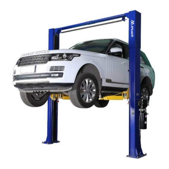
- Page 1 INSTALLATION & OPERATION MANUAL HW-10KOH 2-Post Over Head Car Lift 10,000LB Capacity SONGA ENTERPRISES INC. 8512 122ND AVE NE UNIT 25, KIRKLAND, WA 98033 Phone: 800-616-9618 Text: 425-300-2600 http://www.apluslift.com help@apluslift.com...
-
Page 2: Specification And Features
Specification and Features Heavy duty design: ◦ Column steel thickness: 13/64" ◦ Carriage steel thickness: 15/64" ◦ Carriage yoke thickness: 9/16" ◦ Arm steel thickness: 15/64" ◦ Base plate steel thickness: 5/8" Driving mode: dual hydraulic cylinders, chain drive ... - Page 3 Important Information READ THIS BEFORE INSTALLING THE LIFT! Improper installation can cause injury or damage! Read this installation and operation manual in its entirety before attempting to install the lift. Manufacturer or distributor assumes no responsibility for loss or damage of any kind, expressed or implied, resulting from improper installation or use of this lift.
-
Page 4: Installation Requirements
Installation Requirements Use proper lifting techniques when lifting individual pieces. Use plenty of help when moving lift pieces. Please wear work gloves to protect your hands. The lift should be installed on a leveled floor with a slope of less than 3 degrees. ... -
Page 5: Anchoring Tips
Anchoring Tips Check the following diagram for the footprint of columns with anchor bolts positions. Use a concrete rotary hammer drill with 3/4” drill bit. Do not use excessively worn or incorrectly sharpened drill bits. Keep the drill in a perpendicular position when drilling. Let the drill do the work. Do not apply excessive pressure. - Page 6 Asymmetrical Arm Diagram...
-
Page 7: Installation Instructions
Installation Instructions Step 1 (Preparation) Please carefully remove all the parts from the package. ◦ Remove any loose cables, hoses, part boxes, hydraulic power unit, etc. if they are inside the columns or banded to the columns. ◦ Remove the power unit box and four swing arms. ◦... - Page 8 Step 2 (Installing Columns) Bolt each column extension to each column. Determine the side that the power unit column will be located. The power unit column can be located on either side. Keep in mind this is the column where your main electrical power supply will be connected.
- Page 9 Step 3 (Installing Overhead Beam) Assemble the overhead beam by connecting two short beam pieces with the connector. Bolt two pieces of the connector together Bolt the overhead beam to two columns. Make sure to bolt them together by installing the bolts from inside the beam to avoid interference with the cables when operating the lift.
- Page 10 Step 5 (Installing Power Unit and Routing Hydraulic Hoses) Mount the power unit onto the main side column with four hex bolts. Connect two 4 1/4" fittings to both cylinders. Connect T-fitting to the power unit. Connect short hydraulic hose to the power unit and the cylinder in the power unit post. ...
- Page 11 Step 6 (Installing Swing Arms) Locate the 4 swing arms and swing arm pins. Take one of the arms and insert it over the hole in the carriage torsion tube. Line up the holes and insert the pin. Repeat for the three other arms.
- Page 12 Step 8 (Hydraulic Fluid and Adjustment) Cable Adjustment Place a pair of small or medium vise grips around the shoulder of the long threaded adjusting bolt on the cable to make any adjustments. Use a deep socket to adjust the slack out of the cable. Adjust tension to cables equality.
- Page 13 Step 9 (Installing Safety Bar) Mount safety bar to the overhead beam ◦ Mount switch bracket at the power unit side so that limit switch can be mounted and connected to the power unit ◦ Please note the other end of the safety bar is mounted with a long bolt ...
- Page 14 After open the power unit cover, remove the wire in the picture (from push button to A1 on the contactor) Connect the limit switch wire (recommend gauge 12 wire) to the connector (A1) and start button. Mount the power unit panel and screw tight...
- Page 15 This procedure pumps all the air from the system. Lifting speed will be faster (be normal speed) after air is bled out. Please Check https://www.apluslift.com/pages/faq for Troubleshooting. Please Check Operation, Safety, and Maintenance Before Use.
-
Page 16: Operation
Operation Only authorized personnel can operate the lift. Please read operating and safety procedures carefully before operating the lift. Maintain and inspect lift in accordance with the owner’s manual. Never exceed the capacity. Do not operate a lift that is damaged or in need of repair. ... - Page 17 Safety NEVER WORK UNDER OR NEAR THIS LIFT WITHOUT THE LOCKS BEING ENGAGED. THE POWER UNIT IS NOT DESIGNED TO BE A LOADING-HOLDING DEVICE. NOT USING THE LOCKS WILL RESULT IN A PREMATURE FAILURE TO THE CYLINDERS, PUMP, AND/OR CABLES AND CAN CAUSE SERIOUS PROPERTY DAMAGE OR PERSONAL INJURY! FAILURE TO HEED THIS WARNING WILL RESULT IN IMMEDIATE TERMINATION OF YOUR WARRANTY! FAILURE TO PERFORM THE DAILY PRE-OPERATIONAL CHECK CAN RESULT IN...
-
Page 18: Maintenance
◦ Always the lift vehicle using all four pads. ◦ Never use the lift to raise one end or one side of a vehicle. ◦ Always raise the vehicle about 3” and check for stability by rocking the vehicle. ◦ Prior to lowering the vehicle, walk around the lift and check for any objects that might interfere with the operation of the lift and safety latches;... - Page 19 5. Check the cylinder pulley assembly for free movement or excessive wear on the cylinder yoke or pulley pin. 6. Check the cable pulley for free movement and excessive wear. Yearly Maintenance 1. Lubricate the chains 2. Grease the rub blocks and column surface contacting the rub blocks 3.
-
Page 20: Part List
Part List Item Description Quantity Overhead beam (two beam pieces and one connector) M10×25 hex bolts, washers, and nuts (connect overhead beam pieces) M10×25 hex bolts, spring washers and nuts (connect overhead beam and columns) 8 Safety bar Switch bracket for safety bar (mount on the power unit side). Bolts in item 28 M6×130 bolt for safety bar (mount on the other side) Limit switch with mounting hardware Top columns extension... -
Page 21: Limited Warranty
There is no other express warranty on the APlusLift lifts and this warranty is exclusive of and in lieu of all other warranties, expressed or implied, including all warranties of merchantability and fitness for a particular purpose.
Need help?
Do you have a question about the HW-10KOH-A and is the answer not in the manual?
Questions and answers