Table of Contents
Advertisement
Quick Links
Advertisement
Table of Contents

Related Manuals for APlusLift HW-12S


Summary of Contents for APlusLift HW-12S
- Page 1 Four post vehicle lift Original Operation Manual...
- Page 2 PRINTING CHARACTERS AND SYMBOLS Throughout this manual, the following symbols and printing characters are used to facilitate reading: Indicates the operations which need proper care Indicates prohibition Indicates a possibility of danger for the operators Indicates the direction of access for motor vehicles to the lift BOLD TYPE Important information WARNING: before operating the lift and carrying out any adjustment, read...
-
Page 3: Table Of Contents
CONTENTS GENERAL INFORMATION PRODUCT IDENTIFICATION PACKING, TRANSPORT AND STORAGE PRODUCT DESCRIPTION TECHNICAL SPECIFICATION SAFETY INSTALLATION OPERATION AND USE MAINTENANCE TROUBLESHOOTING... -
Page 4: General Information
CHAPTER 1 – GENERAL INFORMATION This chapter contains warning instructions to operate the lift properly and prevent injury to operators or objects. This manual has been written to be used by shop technicians in charge of the lift (operator) and routine maintenance technician (maintenance operator). -
Page 5: Product Identification
all controls, as well as with the machine features shown in the chapter “Operation and use” WARNINGS Unauthorized changes and/or modifications to the machine relieve the manufacturer of any liability for possible damages to objects or people. Do not remove or make inoperative the safety devices, this would cause a violation of safety at work laws and regulations. -
Page 6: Packing, Transport And Storage
Machines may be updated or slightly modified from an aesthetic point of view and, as a consequence, they may present different features from these shown, this without prejudicing what has been described herein. WARRANTY CERTIFICATE The warranty is valid for a period of 12 months starting from the date of the purchase invoice. The warranty will come immediately to an end when unauthorized modifications to the machine or parts of it are carried out. - Page 7 PACKING The packing of the lift is shown in the figure 1: N. 1 base unit packed in a steel frame, wrapped up in non-scratch material, and N.1 package of power unit. If requested, optional accessories are available to satisfy each customer’s requirements. Figure 1 - PACKAGE 3.2 LIFTING AND HANDLING When loading/unloading or transporting the equipment to the site, be sure to use suitable loading (e.g.
-
Page 8: Product Description
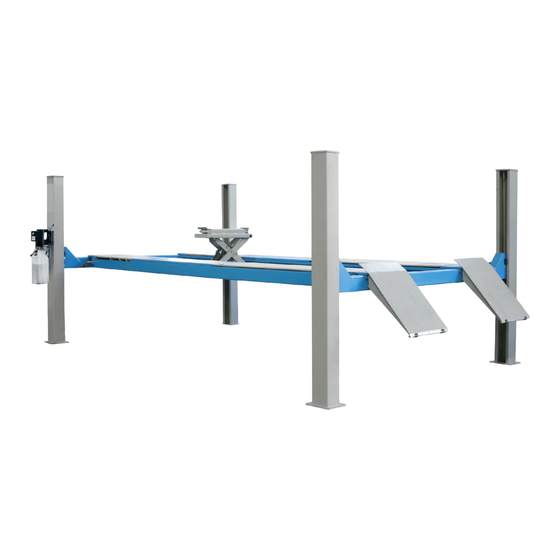
CHAPTER 4 - PRODUCT DESCRIPTION LIFT DESCRIPTION (Ref. Figure 2) The lift is suitable for lifting motor vehicles having maximum weight as described in the nameplate on the power side column of the lift. All mechanical parts have been built in steel plate to make the frame stiff and strong while keeping a low weight. -
Page 9: Technical Specification
CHAPTER 5 - TECHNICAL SPECIFICATION 5.1 SIZE AND MAIN FEATURES (Ref. Figure 3) LIFT CAPACITY 5000kg Maximum raised height 1700mm Runway length 5000mm Runway width 580mm Free width between runways 880/960mm Width between two columns 2880mm Overall length 5825mm Overall height 2220mm Overall width 3286mm... - Page 10 5.2 HYDRAULIC POWER UNIT The hydraulic unit is equipped with Figure 4 – HYDRAULIC POWER UNIT Figure 5 -HYDRAULIC PLAN Motor Lowering speed control valve Oil filter Non return valve Oil tank Manual lowering valve Pressure overload valve Direction converting valve Gear up A10/A11 Hydraulic cylinder...
- Page 12 Figure 6a - ELECTRICAL PLAN (380V) Power switch Scram button Thermal relay Lifting pushbutton Thermal relay Top limit switch Thermal relay Contactor AC Transformer Polit lamp Figure 6b - ELECTRICAL PLAN (220V) Power switch scram button Thermal relay Lifting pushbutton Thermal relay Top limit switch Thermal relay...
-
Page 13: Safety
CHAPTER 6 – SAFETY Read this chapter carefully and completely because it contains important information for the safety of the operator and the person in charge of maintenance. The lift has been designed and built for lifting vehicles and making them stand above level in a closed area. - Page 14 Any use of the lift other than that herein specified can cause serious accidents to people in close proximity of the machine. RISKS FOR PEOPLE All risks the personnel could run, due to an improper use of the lift, are described in this section. PERSONNEL CRUSHING RISKS During lowering of runways and vehicles, personnel must not be within the area covered by the lowering trajectory.
- Page 15 Make sure all areas next to the lift are well and uniformly lit, according to local regulations. 6.8 RISKS OF BREAKING COMPONENT DURING OPERATION Materials and procedures, suitable for the designed parameters of the lift, have been used by the manufacturer to build a safe and reliable product. Operate the lift only for the use it has been designed for and follow the maintenance schedule shown in the chapter “Maintenance”.
-
Page 16: Installation
CHAPTER 7 – INSTALLATION Only skilled technicians, appointed by the manufacturer, or by authorized dealers, must be allowed to carry out installation. Serious damage to people and to the lift can be caused if installations are made by unskilled personnel. Always refer to the exploded views attached during installation. - Page 17 A level floor is suggested for proper installation. Small differences in floor slope may be compensated for by proper shimming. Any major slope change will affect the level lifting performance. If a floor is of questionable slope (more than 3 degrees), considering to pour the new concrete slab. 7.5SITE LAYOUT Determine which end of the lift will be approach side.
- Page 18 Fig.12 Line up the runways with the bolt holes in the transverse beams and temperately bolt the screw M18X120 and the washer D.18 in position. Make sure the cables are routed correctly and make sure that cables on the safety rollers. Before installation, make sure that all accessories have been installed in the runways and transverse beams.
- Page 19 andassemble the nuts M20 on it. Adjust each rack in equal height by tightening or unloosing the nuts. Adjust each cable in equal tension by tightening or unloosing the nuts. Fig.13 7.8ANCHORING COLUMNS Before proceeding, check the measurement referring to the layout figure 2 and make sure that the base plate of each column is square.
- Page 20 Remove the oil level plug on the oil tank and pour oil in the tank about 10 liters. Raising the lift slowly by pressing the lifting button until the lift reaches the full height. DO NOTcontinue pressing the button after lift reaches full height. Damage to motor can occur if continued.
- Page 21 7.13 INSTALLATION OF SAFETY HEIGHT LIMIT SWITCH (fig.14) Install the limit switch on the power side column as shown in the figure 14. Fig.14 7.14 INSTALLATION OF ACCESSORIES (ref. fig. 15) Install all covers onto transverse beams. Install the front wheel stops. Install the drive-on ramps onto the lift.
- Page 22 Bolt M18×120 Drive-on ramp 405-11-00 Ramp shaft Split pin 4×40 Sliding block 401-00-11 Hexagon socket M8×15 Bolt M12×40 7.15 CHECK WITH LOAD WARNING: please follow carefully the instructions in the coming paragraph for avoiding damages on the lift Carried out two or three complete cycles of lowering with the vehicle loaded and lifting and: Repeat the checks provided for by 7.13.
-
Page 23: Operation And Use
Fig.16 Make sure that rail channel is clean of debris. Check the clearance and movement of the jacking beam by sliding it forward and rearward on the rails. Connect the pneumatic line following the instruction on the chapter 7.10. Connect the hydraulic hose. Without a vehicle loaded, raise the jack at full stroke to check for the proper operation. - Page 24 Figure 4 – CONTROLS OF LIFT LIFTING BUTTON (1) 0 When pressed, the power unit is running and the lift can be raised to a desired height until the button is released. SAFETY RELEASE HANDLE (2) When pressed, the mechanical safeties will be released so that the lift can be lowered. LOWERING LEVER(3) When the safety release handle is pressed (the mechanical safeties are released), press the lowering lever in the meantime to lower the lift to the desired height under its weight and the load...
- Page 25 Always ensure that the safety in each column is engaged before any attempt is made to work on or near the vehicle. 8.1.3 LOWERING Be sure the safety area is free of people and objects. Raise the lift high enough by pushing the lifting button to clear off the mechanical safeties.
- Page 26 LOWERING LEVER(The operation is the same as the four post lift)(2) 0 When pressed, the hydraulic fluid is released from the jack cylinder into the oil reservoir of the pump to lower the jack under the weight loaded. Please follow the instruction below if the control panel is equipped: Figure 17 –...
-
Page 27: Maintenance
8.2.3 LOWERING Be sure the safety area is free of people and objects. Lower the jack fully by keeping pressing the lowering lever. CHAPTER 9 - MAINTENANCE Only trained personnel who knows how the lift works, must be allowed to service the lift. -
Page 28: Troubleshooting
The use of water or inflammable liquid is strictly forbidden. Be sure the rod of the hydraulic cylinders is always clean and not damaged since this may result in leakage from seals and, as a consequence, in possible malfunctions. PERIODIC MAINTENANCE Check hydraulic connections and hoses for leaks Daily pre-operation Check safety lock audibly and visually while in operation... - Page 29 Replace if needed The pressure overload valve Check and clean if dirty, or clogged or leaks replace if faulty The lowering valve does not Check and clean if dirty or close. replace if faulty The suction tube or pump filter Check and clean if needed.
Need help?
Do you have a question about the HW-12S and is the answer not in the manual?
Questions and answers