Table of Contents
Advertisement
Quick Links
M PUMPS PROCESS SRL
Via dell'artigianato, 120
Setting Innovative
45015 Corbola (RO) – Italia
Standards
Tel. +39 0426 346304 Fax + 39 0426 349126 1
info@mpumps.it
MECHANICAL SEAL PUMPS
Centrifugal, Vertical, Inline
th
According to API610 – 11
edition
CN SEAL-MV series
User Manual
This copy of the manual is a translation of the italian version
and both manuals must be always furnished together
MODEL: Bare Frame pump with motor
CAUTION
These instructions are intended for operators:
- Pump installation by qualified personnel;
- Use the pump, by staff
- Carry out maintenance / repair of the pump.
Read this instruction manual before using the pump.
Doc. ISM0076_MANUALE_CN SEAL-MV_ENG_REV04.DOCX
Advertisement
Table of Contents

Related Manuals for M Pumps CN SEAL-MV Series


Summary of Contents for M Pumps CN SEAL-MV Series
- Page 1 M PUMPS PROCESS SRL Via dell’artigianato, 120 Setting Innovative 45015 Corbola (RO) – Italia Standards Tel. +39 0426 346304 Fax + 39 0426 349126 1 info@mpumps.it MECHANICAL SEAL PUMPS Centrifugal, Vertical, Inline According to API610 – 11 edition CN SEAL-MV series...
- Page 2 In any case installation manual will take precedence over the pump manual. THIS INSTRUCTION MANUAL is intended to guide those responsible for the installation, operation and maintenance of M PUMPS PROCESS CN SEAL-MV series pumps. Please read it carefully, before you install and operate your M PUMPS PROCESS pump.
-
Page 3: Table Of Contents
5.1. Technical Data................................10 5.2. ALLOWABLE NOZZLES LOADING ..........................11 OPERATING LIMITS AND PERFORMANCES CN SEAL-MV SERIES................13 OUTLINE DRAWINGS ..............................14 NOISE AND VIBRATION ............................... 14 10. CHECKS TO PUMP DELIVERY, STORAGE ........................14 11. SHIPPING AND HANDLING............................14 12. - Page 4 23.1.5. Gaskets and O-rings ............................... 38 23.1.6. Bearings ..................................38 23.1.7. Labyrinths or bearing isolators (if fitted) .......................... 39 Pump reassembling ................................ 39 23.2. 24. DECOMMISSIONING, DISMANTLING AND DISPOSAL OF MATERIALS ..............39 Decommissioning ................................39 24.1. Demolition and dismantling ............................. 39 24.2.
-
Page 5: General Warnings And Safety
This reflects the state of the art at the marketing pump. In case of transfer of the pump, the user is encouraged to report to M PUMPS PROCESS the address of the new owner to facilitate the transmission of any additions to the manual to the new user. -
Page 6: Warranty
WARRANTY Valid for one year from the date of the pump sale. M PUMPS PROCESS do not assume any liability for any warranties explicit or implied, nor as regards the possibility to sell or the suitability of the items supplied. -
Page 7: Nameplate
NAMEPLATE The pump for installation in ordinary environments has the nameplate on the side of the support as shown: only the fields are compiled must be considered relevant and therefore valid for identification. -PUMP SUPPLIED WITH ELECTRIC MOTOR: Doc. ISM0076_MANUALE_CN SEAL-MV_ENG_REV04.DOCX Pag. - Page 8 Pump serial number(s.nr) defines the type of components installed in the pump: Pag. 8/49 Doc. ISM0076_MANUALE_CN SEAL-MV_ENG_REV04.DOCX...
- Page 9 Doc. ISM0076_MANUALE_CN SEAL-MV_ENG_REV04.DOCX Pag. 9/49...
-
Page 10: Pump Description
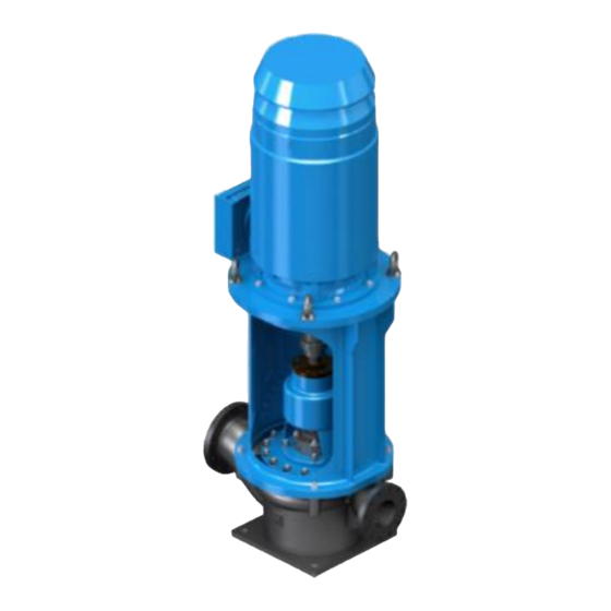
PUMP DESCRIPTION CN SEAL-MV pump series is designed to meets the rigorous requirements of ISO 13709/API 610, eleven edition. A wide range of pump configurations and hydraulic coverage available. Vertical design ensure space-saving and suitability for cryogenic, high temperature and high working pressure services. -
Page 11: Allowable Nozzles Loading
ALLOWABLE NOZZLES LOADING Following table shows nozzles loading of CN SEAL-MV pump series in standard execution. For Special construction please refer to GA drawing sent. PUMP Fx; N Fy; N Fz; N Fr; N Mx; Nm My; Nm Mz; Nm Mr;... - Page 12 PUMP Fx; N Fy; N Fz; N Fr; N Mx; Nm My; Nm Mz; Nm Mr; Nm SIZE Suct. Disch. Suct. Disch. Suct. Disch. Suct. Disch. Suct. Disch. Suct. Disch. Suct. Disch. Suct. Disch. 6x3x10 4980 2140 6220 2660 4100 1780 8960 3860 4600 1900 2360 3520 1440 6260 2560 6x3x13 4980 2140 6220 2660 4100 1780 8960 3860 4600 1900 2360...
-
Page 13: Operating Limits And Performances Cn Seal-Mv Series
OPERATING LIMITS AND PERFORMANCES CN SEAL-MV SERIES Doc. ISM0076_MANUALE_CN SEAL-MV_ENG_REV04.DOCX Pag. 13/49... -
Page 14: Outline Drawings
CHECKS TO PUMP DELIVERY, STORAGE All M PUMPS PROCESS pumps are tested before shipment and carefully packed for transport: at the reception of the pump make sure that the pump has not been damaged during the transport. If there are problems, contact immediately the carrier and inform M PUMPS PROCESS about what happened. -
Page 15: Assembly, Installation, Connections, Commissioning And Setting
Ensure that the heated air from other units does not affect the pump; the air temperature must not exceed 40 °C, for higher temperatures contact your distributor M PUMPS PROCESS; ensure also the free circulation of air cooling of at least ¼ the engine diameter, because either the pump or the motor should be able to dissipate the heat by natural air convection. -
Page 16: Lubrication
Lubrication 14.4. Three options are available for bearings lubrication, - grease, - oil mist - oil cascade inside bearing housing. Ball-Bearings Lubrication by Grease Before placing the pump in operation, it must have grease supplied to the thrust bearings, the line bearing is life greased. - Page 17 Oil Lubricated Ball-Bearings Preparation of bearing housing Bearing frame must be carefully cleaned before filling with oil. It is also good practice to flush it with oil, compatible with the lubricating oil that will be used. The reservoir is to be filled to appropriate level as illustrated in the picture below. The oil level must be maintained at the correct level: decreasing of oil level may cause overheating and failure of the bearings, while exceeding the correct level can result in leakage.
- Page 18 Trico oiler setting (standard) a) Initial fill via top of housing, using overflow plug to establish correct level (refer to the picture above b) Release thumb screw and remove bottle. Establish a measurement from the center line of the oiler connection in bearing housing to the upper cross arm of amounts indicated in the following table this can be obtained by completely screwing down constant level oiler lower arm.
- Page 19 Oil quantity in bearing house OIL LEVEL FROM THE PUMP RANGE PUMP SIZE OIL QUANTITY [Liter] SETTINGS BOTTOM [mm]* OILER [mm]* 2x1½x10 3x1½x10 3x1½x13 3x2x10 3x2x13 4x3x6 2^ RANGE 0.525 4x3x8 4x3x10 6x3x6 6x3x8 6x3x10 6x4x8 8x6x13 8x6x16 8x6x20 10x8x10 4^ RANGE 1.40 10x8x13...
-
Page 20: Checks For The Proper Operation
With regards to the proper commissioning, starting and controls to be carried out before, during and after the first start, please refer to APPENDIX B, which must be filled and returned to M PUMPS to activate product warranty. Pag. 20/49... -
Page 21: Coupling Of The Pump To The Motor
The M PUMPS PROCESS series CN SEAL-MV are ROTATION SENSE: not reversible so the rotation cannot be reversed. The proper direction is clockwise. If you put in front of the pump casing, an arrow indicates the correct direction of rotation; to reverse the direction of rotation may cause damages to the pump. -
Page 22: Features And Installation Of Pump And Motor Assembly
Place the motor, insert thicknesses (about 5mm), under motor flange, so that the two shafts (pump and motor) are coaxial. Leave a space of 3mm between the two elastic coupling halves, and then block the motor with the provided screws. 14.8. -
Page 23: Intended Use Of The Pump. Improper Use. Description Of Functioning.personal Protective Equipment During Use
Instructions for proper use reasonably foreseeable 15.2. Before starting work you must check that: All maintenance actions were properly carried out according to the time intervals set by M PUMPS PROCESS; There are no damaged parts of the pump; All the warning stickers and safety licence plates are present and in good condition and are operating the emergency stop buttons (check through a test). -
Page 24: Residual Risks And Protection Measures To Be Taken
It is incorrect any use of the pump other than that mentioned in the paragraph “Instructions for a proper use reasonably foreseeable”. M PUMPS PROCESS disclaims any liability damages to things and people related to uses for which the pump was not specifically designed and constructed. -
Page 25: Personal Protective Equipment To Wear
Don’t use without permission spare parts not identical to the originals or components not approved by M PUMPS PROCESS; Don’t perform any modification or structural intervention without the approval of M PUMPS PROCESS; After shocks accidentally suffered by the pump, check the pump integrity and perform a check to M PUMPS PROCESS;... -
Page 26: Instructions And Procedures For The Training Of The Personel And For Emergencies
Warning Description signs applied Symbol/indication Quantity Notes Label “check correct pump- motor alignment prior to start“ Label rotation and not run dry indication Hydro-test label Label quality control assembly Internal use INSTRUCTIONS AND PROCEDURES FOR THE TRAINING OF THE PERSONEL AND FOR EMERGENCIES Operators responsible for the various life stages of the pump must be: - For assemblers: staff formed and trained on good practices for handling of goods with the use of tools... -
Page 27: Emission / Dispersion Of Harmful Substances
The head requested exceeds the pump Reduce the total head of the system if possible. head expected. Increase the diameter of the discharge pipe. Check that the discharge valve is fully open. Replace the pump. Consult M PUMPS PROCESS. Doc. ISM0076_MANUALE_CN SEAL-MV_ENG_REV04.DOCX Pag. 27/49... - Page 28 The head requested is lower than pump Increase the diameter of the discharge pipe. head expected. Replace the pump. Consult M PUMPS PROCESS. Insufficient speed Consult M PUMPS PROCESS. Excessive Suction lift Check that NPSHa>NPSHr, suction line losses on strainer and fittings The pump rotates in the opposite Check the direction of rotation.
- Page 29 Replace the motor bearings, investigate the causes of worn breakage. Motor under dimensioned Mount a more powerful motor (check in advance with your distributor M PUMPS PROCESS ). Motor overload threshold set incorrectly the security settings of the motor Check The guard against the motor dry running Control flow decreases or fluid intake.
- Page 30 Check that flow is superior than minimum permitted. Operating at high flow Check that flow is superior than maximum permitted. Unbalanced Impeller. Consult M PUMPS PROCESS. Wear of the coupling motor-pump Replace the coupling and proceed to the realignment of pump and motor.
-
Page 31: Periodic And Extraordinary Maintenance
M PUMPS PROCESS. If the hydraulic pump is washed with jet in pressure, prevent the entry of water into the terminal of the motor. -
Page 32: Emptying Of The Fluid Contained In The Pump
The extraordinary maintenance operations concern the activities that are beyond those typically programmable and executable; they require precise technical expertise by qualified personnel, and then you should contact M PUMPS PROCESS. Delivery is the one shown in the back cover of this manual. DANGER... -
Page 33: The Periodic Maintenance Specified In The" Periodic And Extraordinary Maintenance
M PUMPS PROCESS referring to the model of the pump, employee number, description of the component and the quantity needed. When you see elements with rust, cracks, etc, you must perform all replacements/repairs necessary to re-establish the conditions of the pump safe working. -
Page 34: Pull Out Element Removal
equipment. 22.1.1. Pull Out Element Removal This pump has a pull-out element, which consists of the pump shaft (12), mechanical seal assembly (21), casing cover (9), impeller (7), and bearing housing assembly, as well as their attached parts. This pull-out element makes it unnecessary to remove the driver, motor bracket (6), or casing (1) to service the bearing housing assembly, mechanical seal (21), impeller (7), wear rings (8.1/8.2–3.1/3.2), stuffing box bushing (10), and gaskets. -
Page 35: Pull Out Element Disassembly
Fig. 6.2 The lifting arm is not supplied with the pump. It must be ordered apart. h) Raise the pullout element upward until the impeller clears the lower flange of the support head (6) and remove through the large opening in the support head. i) Remove the casing cover gasket (16) from the casing (1) or casing cover (9) and discard. - Page 36 g) Unscrew cap screws that hold bearing housing (32) to casing cover (9) and tap casing cover and bearing housing with mallet to break cover loose from housing. The impeller cap nut (20) is left hand threaded. To remove the impeller cap nut, turn it to the right (clockwise) while facing the impeller.
-
Page 37: Examination Of Parts
Facing the bearing nut, turn it clockwise to loosen. Remove lock nut and lock washer from shaft. t) Remove shaft from vice and press bearings (15 – 14) off shaft with hydraulic press, if available; otherwise, leave shaft in vice and pull bearings off shaft with a bearing puller. Slide the deflector ring (23) off of the shaft. -
Page 38: Throat Bush (If Fitted)
b) It is recommended that when reassembling mechanical seal new "O" rings and gaskets be used. c) Refer to manufacturers drawing for assembly of mechanical seal. Refer to mechanical seal section within this manual for further details. 23.1.3. Throat Bush (If fitted) a) Check the throat bush and replace if required. -
Page 39: Labyrinths Or Bearing Isolators (If Fitted)
CAUTION A good stocking will guarantee against unpleasant incidents during the restarting of the pump. M PUMPS PROCESS disclaims any responsibility for machines stored incorrectly. If you intend to stop using this pump it is recommended to make it inoperative. -
Page 40: Exploded View Part List
EXPLODED VIEW PART LIST PART LIST N° DESCRIZIONE DESCRIPTION Corpo pompa Pump casing Piastra base corpo pompa Baseplate pump casing Anello usura corpo pompa Pump casing wear ring Anello usura corpo pompa Pump casing wear ring Prigioniero Stud nut Pag. 40/49 Doc. - Page 41 Prigioniero Stud nut Prigioniero Stud nut Garlock Labyrinth seal Supporto motore Bracket Girante Impeller Anello usura girante Impeller wear ring Anello usura girante Impeller wear ring Cassastoppa Stuffing box Bussola di findo fissa Fixed bushing Tubo ricircolo olio Flushing pipe Albero Shaft Bussola di findo rotante...
- Page 42 PART LIST N° DESCRIZIONE DESCRIPTION Corpo pompa Pump casing Piastra base corpo pompa Baseplate pump casing Anello usura corpo pompa Pump casing wear ring Anello usura corpo pompa Pump casing wear ring Prigioniero Stud nut Prigioniero Stud nut Prigioniero Stud nut Ventola Pag.
- Page 43 Supporto motore Bracket Girante Impeller Anello usura girante Impeller wear ring Anello usura girante Impeller wear ring Cassastoppa Stuffing box Bussola di findo fissa Fixed bushing Coprigiunto Coupling guard Albero Shaft Bussola di findo rotante Rotary bushing Cuscinetto a sfere Ball bearing Cuscinetto a sfere obliquo Oblique ball bearing...
-
Page 44: Notes
NOTES Pag. 44/49 Doc. ISM0076_MANUALE_CN SEAL-MV_ENG_REV04.DOCX... -
Page 45: Appendix A - Register Of Maintenance And Periodic Checks Of The Pump
APPENDIX A – Register of maintenance and periodic checks of the pump It is provided a list of maintenances to be carried out and their respective ranges; you must register these operations. Commissioning date: ____________________ Main maintenance operations to be performed by the second year of use onwards: Warnings and protective measures Required check be taken to perform maintenance... -
Page 46: Appendix B - Startup Check List
APPENDIX B – Startup check list PUMP SERIES CN SEAL-MV Rev. N°00 - Do not destroying – do not modify - Date 21/02/2013 This document consists STARTUP CHECK LIST of 2 pages NO / YES / Description of activity ... - Page 47 Have the Pump Bearings been filled with recommended Lubricating Oil and to the stated level (For Long Coupled Pump)? Have the motor Bearings been greased if required? * PRE START-UP For High /Low Temperature Pumping application , has the pump been warmed up to required Temperature? Can the Pump shaft turns freely by hand? Fully Open the Suction Valve.
- Page 48 Under Normal Condition, continuously run the pump under observation for one or two hours. COMMENTS/REMARKS: INSTALLATION REFERENCE: CONTACT: PROJECT: CONTRACTOR: ADDRESS: FAX: PHONE NO: SERIAL NR: PUMP MODEL NO: IMPELLER MOTOR TYPE: DIAMETER: FOLLOW UP START-UP BY: REQD: DATE: SIGNATURE: Please send this document, duly completed, to the e-mail: info@mpumps.it, or by FAX at: +39 0426 349126 Pag.
- Page 49 M PUMPS PROCESS S.R.L. Sede Legale: Via Milite Ignoto, 51 – 45019 – Taglio di Po – (RO) – Italy Sede operativa: Via dell’Artigianato, 120 - 45015 Corbola (RO) – Italy Tel.: +39 0426 346304 Fax: +39 0426 349126 E-mail: info@mpumps.it Doc.
Need help?
Do you have a question about the CN SEAL-MV Series and is the answer not in the manual?
Questions and answers