Advertisement
Available languages
Available languages
Quick Links
CARDIN ELETTRONICA spa
Via del lavoro, 73 – Z.I. Cimavilla
3 1 0 1 3 C o d o g n è ( T V ) I t a l y
Tel:
Fax:
email (Italian): Sales.office.it@cardin.it
email (Europe):
Http:
AUTOMAZIONE PER CANCELLI A BATTENTE
AUTOMATION FOR HINGED GATES
AUTOMATISME POUR PORTAILS BATTANTS
AUTOMATIZACIÓN PARA CANCILLAS BATIENTES
ITALIANO
ATTENZIONE! Prima di iniziare l'installazione leggere le
istruzioni attentamente!
Esempio di installazione
Schema di montaggio
Schema elettrico (impianto tipo)
Avvertenze importanti
Istruzione per l'installazione
Sblocco manuale
Collegamento elettrico
Procedura di programmazione
Riposizionamento automatico
Comando via radio
Modalità di funzionamento
Funzionamento a batteria
Caratteristiche tecniche
ENGLISH
ATTENTION! Before installing this device read the
following instructions carefully!
Installation example
Assembly
Wiring diagram (installation example)
Important remarks
Installation instructions
Manual release mechanism
Electrical connection
Programming procedure
Repositioning
Remote control
Function modes
Battery powered operation
Technical specifications
BL
+39/0438.404011
+39/0438.401831
24Vdc
Motors
Sales.office@cardin.it
www.cardin.it
DREHTORANTRIEBE
Pagina
2
Pagine
3-5
Pagina
6
Pagina
7
Pagine
7-8
Pagina
8
Pagine
8-9
Pagina
10-12
Pagina
12
Pagina
12
Pagine
13
Pagina
13
Pagina
48
Page
2
Pages
3-5
Page
6
Page
15
Pages
15-16
Page
16
Pages
16-17
Page
18-20
Page
20
Page
20
Pages
21
Page
21
Page
48
Instruction manual
Series
BL
ZVL474.03
Questo prodotto è stato testato e collaudato nei laboratori della casa costruttrice, la quale ne ha verificato la
perfetta corrispondenza delle caratteristiche con quelle richieste dalla normativa vigente. This product has been
tried and tested in the manufacturer's laboratory who have verified that the product conforms in every aspect to
the safety standards in force. Ce produit a été testé et essayé dans les laboratoires du fabriquant. Pour l'installer
suivre attentivement les instructions fournies. Dieses Produkt wurde in den Werkstätten der Herstellerfirma
auf die perfekte Übereinstimmung ihrer Eigenschaften mit den von den geltenden Normen vorgeschriebenen
getestet und geprüft. Este producto ha sido probado y ensayado en los laboratorios del fabricante, que ha
comprobado la perfecta correspondencia de sus características con las contempladas por la normativa vigente.
24 Vdc Motors
(firmware V1.0)
FRANÇAIS
ATTENTION! Avant de commencer la pose, lire
attentivement les instructions!
Exemple d'installation
Schéma de montage
Schéma électrique (exemple d'installation)
Consignes importants
Instructions pour l'installation
Déverrouillage manuel
Branchement électrique
Procédé de programmation
Repositionnement
Commande via radio
Modes de fonctionnement
Fonctionnement à batterie
Caractéristiques techniques
DEUTSCH
ACHTUNG! Bevor mit der Installation begonnen wird, sollte
die Anleitung aufmerksam gelesen werden!
Anlagenart
Montagegearbeiten
Elektrischer Schaltplan (Anlagenart)
Wichtige Hinweise
Installationsanleitung
Manuelle Entriegelung
Elektrischer Anschluss
Programmierverfahren
Neupositionierung
Funkbefehl
Betriebsmodus
Batteriebetrieb
Technische Eigenschaften
ESPAÑOL
¡ATENCIÓN! Antes de iniciar la instalación del sistema,
leer atentamente las instrucciones.
Instalación estándar
Esquema de montaje
Esquema eléctrico (instalación estándar )
Advertencias importantes
Instrucciones para la instalación
Desbloqueo manual
Conexionado eléctrico
Procedimiento de programación
Reposicionamiento
Mando vía radio
Modalidad de funcionamiento
Indicaciones en el display
Datos técnicas
Model
Date
224E
13-09-2005
Multi
Decoding
200/BL224E
Page
2
Pages
3-5
Page
6
Page
23
Pages
23-24
Page
24
Pages
24-25
Page
26-28
Page
28
Page
28
Pages
29
Page
29
Page
48
Seite
2
Seiten
3-5
Seite
6
Seite
31
Seiten
31-32
Seite
32
Seiten
32-33
Seite
34-36
Seite
36
Seite
36
Seiten
37
Seite
37
Seite
48
Página
2
Páginas
3-5
Página
6
Página
39
Páginas
39-40
Página
40
Páginas
40-41
Página
42-44
Página
44
Página
44
Páginas
45
Página
45
Página
48
Advertisement

Related Manuals for Cardin 200/BL224E


Summary of Contents for Cardin 200/BL224E
- Page 1 CARDIN ELETTRONICA spa Instruction manual Series Model Date Via del lavoro, 73 – Z.I. Cimavilla ZVL474.03 224E 13-09-2005 3 1 0 1 3 C o d o g n è ( T V ) I t a l y Questo prodotto è stato testato e collaudato nei laboratori della casa costruttrice, la quale ne ha verificato la Tel: +39/0438.404011...
- Page 2 14 Fotocellule laterali di protezione (FS) Attenzione: Lo schema rappresentato è puramente indicativo e viene fornito come base di lavoro al fine di consentire una scelta dei componenti elettronici Cardin da utilizzare. Detto schema non costituisce pertanto vincolo alcuno per l'esecuzione dell'impianto ZEICHENERKLÄRUNG...
- Page 3 SCALA: 1:2 Description : Drawing number : DI0424 CORSA “B” SCHEMA DI MONTAGGIO BL224ESB Product Code : BL224ESB Draft : P.J.Heath Date : 07-03-2005 CARDIN ELETTRONICA S.p.A - 31020 San Vendemiano (TV) Italy - via Raffaello, 36 Tel: 0438/401818 Fax: 0438/401831...
- Page 4 Lock Product Code : BL224 P.J.Heath Date : Draft : 10-03-2005 CARDIN ELETTRONICA S.p.A - 31020 San Vendemiano (TV) Italy - via Raffaello, 36 Tel: 0438/401818 Fax: 0438/401831 Unlock SCALA: 1: Description : Prodotti Prodotti Cardin Drawing number : DI0425...
- Page 5 Draft : P.J.Heath Date : 21-02-2006 CARDIN ELETTRONICA S.p.A - 31020 San Vendemiano (TV) Italy - via Raffaello, 36 Tel: 0438/401818 Fax: 0438/401831 PREINSTALLAZIONE STAFFA POSTERIORE/ANTERIORE - PRE-INSTALLATION FRONT/REAR BRACKET PRÉINSTALLATION PATTE POSTÉRIEURE/ANTÉRIEURE - VORMONTAGE HINTERER/VORNER HALTEBÜGEL PREINSTALACIÓN SOPORTE POSTERIOR/ANTERIOR 44.5 mm...
- Page 6 ANQ800-1 External antenna (868 MHz) Date : Draft : P.J.Heath 05-09-2015 LEGEND ZEICHENERKLÄRUNG LEYENDA CARDIN ELETTRONICA S.p.A - 31020 San Vendemiano (TV) Italy - via Raffaello, 36 Tel: 0438/401818 Fax: 0438/401831 Flashing warning lights Blinklicht Relampagueador Indicator light Kontroll-Lampe Luz testigo FTC-RX...
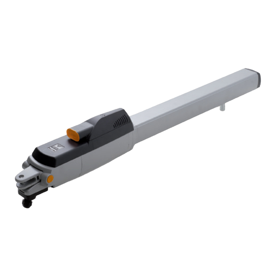
- Page 7 DESCRIZIONE TECNICA e lubrificazione (importante che la cerniera superiore e quella inferiore siano a piombo 200/BL224E L’attuatore è adatto all’automazione di ante battenti (fino a 2,2 m, 200 kg di tra loro). peso per anta) ed è costituito da un insieme compatto e tenace dove un efficiente motore •...
- Page 8 • Far traslare la chiocciola dell'attuatore (part. 4 fig. 2) fino ad arrivare a 15 mm dal AVVERTENZE IMPORTANTI completamento della corsa in chiusura e portare ruotandoli in posizione ottimale le battute meccaniche "7" e "9" (fig. 2) situate sulla vite. Attenzione! In nessun punto della scheda del programmatore è...
- Page 9 Collegamenti morsettiera CMN comune per tutti gli ingressi/uscite TB FI TA TD Si tenga presente che nel caso sia abilitato il ELS uscita per elettroserratura 12 Vdc – 15 W test, tra la ricezione del comando e il moto delle 9-10 LC-CH2 uscita (contatto puro, N.A.) per attivazione luce di cortesia (alimen- FS CP TC TAL...
- Page 10 PROCEDURA DI PROGRAMMAZIONE (impostazione dei parametri) • Tutte le funzioni della centralina sono impostabili tramite menu sul Display "LCD1" con i tre tasti posti sotto ad esso: - utilizzare le freccie per navigare all'interno dei menù e/o per la regolazione del contrasto del display; - utilizzare "PROG/OK"...
- Page 11 • È necessario impostare i parametri di funzionamento fondamentali (es. la presenza dell'elettroserratura ON/OFF) al menu opzioni. • Se sono presenti delle sicurezze con contatto 8.2k, cambiare l'impostazione al menu sicurezze. • Prima di procedere alla programmazione della corsa del cancello impostare il motore corretto alla voce "selezione motore" del menu "MOTO". Selezione della lingua: PROGRAM TB FI...
- Page 12 PROCEDURA DI PROGRAMMAZIONE COMANDO VIA RADIO (corsa del cancello e sensore di corrente) È possibile azionare a distanza l'automazione tramite radiocomando; ciascun canale • È obbligatoria la presenza delle battute di apertura e chiusura. è configurabile scegliendo tra 5 funzioni disponibili: apertura - chiusura - apertura •...
- Page 13 P.J.Heath I morsetti "9","10" forniscono solamente un contatto puro, e non danno una ten- CARDIN ELETTRONICA S.p.A - 31020 San Vendemiano (TV) Italy - via Raffaello, 36 Tel: 0438/401818 Fax: 0438/401831 1) Automatica sione all’esterno; questo significa che per usare la luce di cortesia sarà necessario alimentare il circuito a parte, ed usare il contatto come semplice interruttore.
- Page 14 FUNZIONAMENTO A BATTERIA MANUTENZIONE Il dispositivo permette il funzionamento del sistema anche in assenza di rete. Per usufruire della garanzia di 24 mesi o di 50000 manovre • Il programmatore dispone di un circuito di carica per batteria NiMH a 24V gestito leggere attentamente le seguenti note.
- Page 15 • Work out the run of the cables according to the command and control devices 200/BL224E The operator is suitable for automating hinged gates (up to 2,2 m in length fitted and make sure the system conforms to the local standard and regulations and 200 kg in weight per gate leaf) and consists of a compact and tenacious appliance in force (see installation example fig.
- Page 16 • Rotate the worm screw lead nut (part. 4 fig. 3) until it reaches 15 mm from the IMPORTANT REMARKS end of the closing direction travel distance and rotate the mechanical travel rings "7" and "9" along the screw to their optimum position. Attention! There is no 230 Vac contact on any part of the electronic card: •...
- Page 17 Terminal board connections CMN common for all inputs and outputs. If the test is active there will be a 1 second delay TB FI TA TD ELS electric lock output (fed continuously) 12 Vdc - 15 W. between the command transmission and move- FS CP TC TAL 9-10 LC-CH2 Potential free contact for the activation of the courtesy light (separate...
- Page 18 PROGRAMMING PROCEDURE (parameter setting) • All the functions of the electronic programmer can be set in the Display menu "LCD1" using the three buttons contained therein: - use the arrows to navigate through the menu and/or to adjust the display contrast; - use "PROG/OK"...
- Page 19 • Set the main operating parameters (e.g. the presence of an electric lock ON/OFF) in the options menu. • If you have safety devices working with 8.2k contacts select the correct setting from the safety device menu. • Before programming the gate travel distances select the correct motor in the "Motion" menu. Language choice: PROGRAM •...
- Page 20 PROGRAMMING PROCEDURE REMOTE CONTROL (gate travel distance and current sensor) The system can be remotely activated using radio control devices; each • The installation of both anti-derailment buffers is absolutely obliga- channel has a choice of 5 possible functions: open - shut - limited open- tory.
- Page 21 29-10-2013 1) Automatic as follows: CARDIN ELETTRONICA S.p.A - 31020 San Vendemiano (TV) Italy - via Raffaello, 36 Tel: 0438/401818 Fax: 0438/401831 Selected by enabling automatic reclosing (Automatic reclosing "ON" on • Jumper J5 in position 1: the display). When the gate is completely closed the opening command will the contact is closed by a timer and works as a “courtesy light"...
- Page 22 Battery check BATTERY POWERED OPERATION With the gate in the completely closed position and the display switched off. This device allows the propulsion unit to work during blackouts. Check that LED "L3" (battery charging) is giving off "one flash at a time". Switch off the power at the mains and make sure that the display indicates •...
- Page 23 • Fixer la patte postérieure au pilier (fig.7 page 5) en respectant les cotes "A" et "B" • Logement bornier pour le câblage avec câble Cardin CABPC10, doté de couvercle (fig. 4 page 4), après avoir contrôlé la position de la penture du portail par rapport et de presse-étoupe incorporé.
- Page 24 • Déplacer la noix de l’opérateur (dét. 4 fig. 2) de façon à la faire arriver à 15 mm CONSIGNES IMPORTANTES! de la fin de la course en fermeture et placer les butées mécaniques "7" et "9" (fig. 2) situées sur la vis, en les faisant tourner, dans une position optimale. Attention! En aucun point de la carte du programmateur il y a une tension de •...
- Page 25 Branchements du bornier Tenir compte du fait qu’en cas de validation du test, CMN commun pour toutes les entrées/sorties 1 seconde environ s’écoule entre la réception de la TB FI TA TD ELS sortie pour serrure électrique 12 Vdc – 15 W commande et le lancement de la manœuvre du/des FS CP TC TAL...
- Page 26 PROCÉDÉ DE PROGRAMMATION (paramétrage) • Toutes les fonctions de la centrale sont programmables au moyen du menu sur l'afficheur "LCD1" et avec les trois touches situées sous celui-ci: - utiliser les flèches pour naviguer dans les menus et/ou pour régler le contraste de l'afficheur; - utiliser "PROG/OK"...
- Page 27 • Il est nécessaire de programmer les paramètres de fonctionnement fondamentaux (par exemple la présence de la serrure électrique ON/OFF) au menu Options. • S’il y a des dispositifs de sécurité avec contact 8.2k, modifier le réglage dans le menu Sécurités. •...
- Page 28 PROCÉDÉ DE PROGRAMMATION COMMANDE PAR RADIO (course du portail et senseur de courant) Il est possible d’actionner à distance l’automatisme par le biais d’une télé- • Il est obligatoire d’installer les fins de course en ouverture et en fermeture. commande radio; chaque canal est configurable en sélectionnant une des •...
- Page 29 P.J.Heath Sélectionnable en validant la refermeture automatique (Ref. automatique CARDIN ELETTRONICA S.p.A - 31020 San Vendemiano (TV) Italy - via Raffaello, 36 Tel: 0438/401818 Fax: 0438/401831 ÉCLAIRAGE DE ZONE / SORTIE CH2 RADIO sur "ON" sur l’afficheur). En partant de la condition de portail complètement Les bornes "9"...
- Page 30 Clignotements courts: une variation de tension a été détectée sur les bornes FONCTIONNEMENT À BATTERIE de la batterie comme quand on la branche ou quand Le dispositif permet le fonctionnement du groupe opérateur même en cas on l’enlève; de coupure de courant. Clignotements longs: ils se répètent toutes les 2 secondes pour indiquer •...
- Page 31 TECHNISCHE BESCHREIBUNG • Den Kabelverlauf gemäß den Installationserfordernissen der Steuer- und Sicherheitsvor- 200/BL224E Der Antrieb ist zur Betätigung von Torflügeln (bis 2,2 m, 200 kg Gewicht pro richtungen gemäß den Sicherheitsnormen (siehe Anlagenart Abb. 1, S. 2) vorbereiten. Torflügel) geeignet und besteht aus einer kompakten und widerstandsfähigen Kombination •...
- Page 32 • Die Schneckenschraube des Antriebes (Teil 4, Abb. 2) bis auf 15 mm vor die vollstän- WICHTIGE HINWEISE dige Schließung drehen und die mechanischen Anschläge "7" und "9" (Abb. 2) durch Achtung! An keiner Stelle auf der Leiterplatte der Steuerung befindet sich die Drehung auf der Schraube in die optimale Position bringen.
- Page 33 Anschlussklemmleisten-Anschlüsse Es ist zu beachten, dass bei eingeschaltetem Test CMN Neutralleitung für alle Eingänge/Ausgänge TB FI TA TD zirka 1 Sekunde zwischen dem Befehlseingang und ELS Ausgang für Elektroschloss 12 Vdc – 15 W der Inbewegungssetzung des Torflügels oder der FS CP TC TAL 9-10 LC-CH2 Ausgang (stromfreier Kontakt N.O.) für Aktivierung des Wachlichtes (getrennt...
- Page 34 PROGRAMMIERVERFAHREN (Einstellungen der Parameters) • Alle Funktionen des Steuergeräts können über das Menü im Display "LCD1" mit den drei darunterliegenden Tasten eingestellt werden: - Für das Navigieren im Menü und/oder die Einstellung des Kontrasts im Display die Pfeile benutzen; - “PROG/OK” für die Änderung der Einstellung des ausgewählten Parameters und/oder für die Bestätigung benutzen. PROGRAM OPTIONEN OPTIONEN...
- Page 35 • Die wesentlichen Betriebsparameter (z.B. das Vorhandensein des Elektroschlosses ON/OFF) muss im Menü Optionen eingestellt werden. • Wenn Sicherheitsvorrichtungen mit Kontakt 8.2 kΩ, vorhanden sind, ist die Einstellung im Menü Sicherheitsvorrichtungen zu ändern. • Vor der Programmierung des Torlaufs ist der richtige Motor unter der Position "Motorauswahl" des Menüs "Bewegung" auszuwählen. Auswahl der Sprache: PROGRAM •...
- Page 36 PROGRAMMIERVERFAHREN BEFEHLEINGABE ÜBER FUNK (Torlauf und Stromsensor) Die Automatisierung kann mittels einer Funkfernsteuerung ferngesteuert • Das Vorhandensein der Anschläge ist obligatorisch. werden; jeder Kanal kann konfiguriert werden, indem aus den 5 verfügbaren • Sicherstellen, dass sich die Sicherheitsvorrichtungen in Ruheposition Funktionen ausgewählt wird: Öffnen - Schließen –...
- Page 37 WACHLICHT/FUNKAUSGANG CH2 Sie wird ausgewählt, indem das automatische Wiederschließen freigegeben CARDIN ELETTRONICA S.p.A - 31020 San Vendemiano (TV) Italy - via Raffaello, 36 Tel: 0438/401818 Fax: 0438/401831 Die Klemmen “9” und ”10” hängen von den C-N.O. Kontakten eines Relais wird (Autom. Wiederschl. "ON" im Display). Ausgehend vom vollständig ab;...
- Page 38 Einzelnes Blinken: Wiederholt sich alle 2 Sekunden und zeigt an, dass sich BATTERIEBETRIEB die Batterie in der Phase der Erhaltungsladung befindet; Die Vorrichtung erlaubt den Betrieb des Systems auch bei fehlender Netzversorgung. Eingeschaltet: Die Batterie wird geladen. Die Ladezeit hängt von unterschiedlichen Faktoren ab und kann höchstens 16 •...
- Page 39 (suministrado con el buje insertado en cota 145 mm) o reducido 105 mm, moviendo • Alojamiento de la placa de bornes para el cableado con cable Cardin CABPC10 el buje de rotación en el primer orificio (fig. 7a) y cortando el estribo en el punto "A"...
- Page 40 • Extraer el cárter de protección del tornillo sinfin (todo el sistema tornillo sinfin, tornillo ADVERTENCIAS IMPORTANTES patrón, tacos ajustables de seguridad resultará expuesto). • Mover el tornillo patrón del operador (part. 4, fig. 2) hasta llegar a 15 mm antes de que termine el recorrido durante el cierre y situar -girándolos en posición ideal- los topes ¡Atención! En ningún punto de la tarjeta del programador está...
- Page 41 Conexionado placa de bornes Considerar que si el test está habilitado, trans- CMN Común para todas las entradas/salidas curre aproximadamente un segundo tras la TB FI TA TD recepción de un mandato y el movimiento de ELS salida para cerradura eléctrica 12 Vdc–15W la/las hoja/hojas.
- Page 42 PROCEDIMIENTO DE PROGRAMACIÓN (configuración de los parámetros) • Todas las funciones de la centralita pueden configurarse mediante el menú en el Display "LCD1" con las tres teclas situadas debajo del mismo: - utilizar las flechas para navegar en los menús y/o para regular el contraste del display; - utilizar "PROG/OK"...
- Page 43 • Es necesario configurar los parámetros de funcionamiento fundamentales (p. ej.: la presencia de la electrocerradura ON/OFF) en el menú opciones. • Se sono presenti delle sicurezze con contatto 8.2k, cambiare l'impostazione al menu sicurezze. • Prima di procedere alla programmazione della corsa del cancello impostare il motore corretto alla voce "selezione motore" del menu "MOTO". Selección del idioma: PROGRAM •...
- Page 44 PROCEDIMIENTO DE PROGRAMACIÓN MANDO POR RADIO (carrera de la cancilla y sensor de corriente) Es posible accionar a distancia la automatización por medio del mando por • Es obligatoria la presencia de los topes de apertura y cierre. radio; cada canal puede configurarse seleccionando entre 5 funciones dispo- •...
- Page 45 29-10-2013 por el espacio que había cerrado la cancilla). CARDIN ELETTRONICA S.p.A - 31020 San Vendemiano (TV) Italy - via Raffaello, 36 Tel: 0438/401818 Fax: 0438/401831 Se selecciona habilitando el cierre automático (Cierre automático "ON" en Nota: el mando de apertura limitada puede darse usando también le mando el display).
- Page 46 Prueba de las baterías FUNCIONAMIENTO A BATERÍA Colocar la cancilla en posición de cierre completo: el display está apagado. El dispositivo permite el funcionamiento del sistema también cuando falta Comprobar que el led "L3" (batería en carga) señale el "relampagueo lento". la corriente.
- Page 47 Die CE-Konformitätserklärungen für die Cardin-Produkte stehen in der Originalsprache auf der Homepage www.cardin.it im Bereich "Normen und Zertifizierung" zur Verfügung unter dem Link: Las declaraciones de conformidad CE de los productos Cardin se encuentran disponibles en el idioma original en el sitio www.cardin.it en la secci—n "normas y certificaciones” en el enlace:...
- Page 48 C A R D I N E L E T T R O N I C A s p a Via del lavoro, 73 – Z.I. Cimavilla 31013 Codognè (TV) Italy Tel: +39/0438.404011 Fax: +39/0438.401831 email (Italian): Sales.office.it@cardin.it email (Europe): Sales.office@cardin.it Http: www.cardin.it...
Need help?
Do you have a question about the 200/BL224E and is the answer not in the manual?
Questions and answers