Table of Contents
Advertisement
Quick Links
Advertisement
Table of Contents

Related Manuals for DFI HD101-H81


Summary of Contents for DFI HD101-H81
- Page 1 HD101-H81 Mini-ITX Industrial Motherboard User’s Manual A27450621...
-
Page 2: Copyright
Copyright FCC and DOC Statement on Class B This publication contains information that is protected by copyright. No part of it may be re- This equipment has been tested and found to comply with the limits for a Class B digital produced in any form or by any means or used to make any transformation/adaptation without device, pursuant to Part 15 of the FCC rules. -
Page 3: Table Of Contents
Table of Contents USB Ports ....................23 Audio ......................24 I/O Connectors ................... 25 SATA (Serial ATA) Connectors ..............25 Peripheral Power Connector................. 25 Copyright ......................2 Cooling Fan Connectors................26 Digital I/O Connector .................. 26 Trademarks ......................2 Digital I/O Power Connector ................ 26 Front Panel Connector ................ -
Page 4: About This Manual
About this Manual Static Electricity Precautions An electronic file of this manual is included in the CD. To view the user’s manual in the CD, in- It is quite easy to inadvertently damage your PC, system board, components or devices even sert the CD into a CD-ROM drive. -
Page 5: About The Package
About the Package The package contains the following items. If any of these items are missing or damaged, please contact your dealer or sales representative for assistance. • One HD101 motherboard • One Serial ATA data with power cable • One I/O shield •... -
Page 6: Chapter 1 - Introduction
• 2 RJ45 LAN ports Note: • 2 USB 2.0 ports *Optional and is not supported in standard model. Please contact your sales represen- • 2 USB 3.0 ports • Mic-in, Line-in and Line-out jacks tative for more information. Chapter 1 Introduction www.dfi.com... -
Page 7: Features
This function allows you to use the PS/2 keyboard or PS/2 mouse to power-on the system. Important: Important: The 5V_standby power source of your power supply must support ≥720mA. The 5V_standby power source of your power supply must support ≥720mA. Chapter 1 Introduction www.dfi.com... - Page 8 USB 1.1 (12Mb/s). USB 3.0 reduces the time required for data transmission, reduces power consumption, and is backward compatible with USB 2.0. It is a marked improvement in device transfer speeds between your computer and a wide range of simultaneously accessible external Plug and Play peripherals. Chapter 1 Introduction www.dfi.com...
-
Page 9: Chapter 2 - Hardware Installation
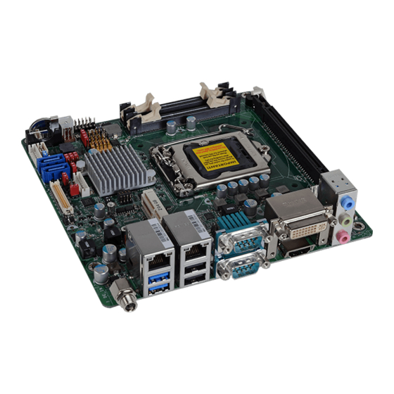
Chapter 2 Chapter 2 - Hardware Installation Important: Board Layout Electrostatic discharge (ESD) can damage your board, processor, disk drives, add-in boards, and other components. Perform installation procedures at an ESD workstation only. If such a station is not available, you can provide some ESD protection by wear- ing an antistatic wrist strap and attaching it to a metal part of the system chassis. -
Page 10: Installing The Dimm Module
Chapter 2 Installing the DIMM Module The system board supports the following memory interface. Note: Single Channel (SC) The system board used in the following illustrations may not resemble the actual Data will be accessed in chunks of 64 bits (8B) from the memory channels. board. -
Page 11: Cpu
Chapter 2 6. Grasping the module by its edges, position the module above the socket with the “notch” in the module aligned with the “key” on the socket. The keying mechanism ensures the module can be plugged into the socket in only one way. The system board is equipped with a surface mount LGA 1150 socket. -
Page 12: Installing The Cpu
Chapter 2 Load lever Installing the CPU 5. Lifting the load lever will at the same time lift the load plate. 1. Make sure the PC and all other peripheral devices connected to it has been powered down. Lift the load lever up to 2. - Page 13 Chapter 2 8. Close the load plate then 7. Insert the CPU into the push the load lever down. socket. The gold triangular mark on the CPU must While closing the load align with the corner of plate, make sure the front the CPU socket shown on Retention knob edge of the load plate...
-
Page 14: Installing The Fan And Heat Sink
Chapter 2 Installing the Fan and Heat Sink 4. Rotate each push-pin ac- cording to the direction of the arrow shown on top of The CPU must be kept cool by using a CPU fan with heat sink. Without sufficient air circula- the pin. -
Page 15: Jumper Settings
Chapter 2 Jumper Settings PS/2 Keyboard/Mouse Power Select Clear CMOS Data 1-2 On: Normal (default) 1-2 On: +5V (default) 2-3 On: Clear CMOS Data 2-3 On: +5V_standby JP1 is used to select the power of the PS/2 keyboard/mouse port. Selecting +5V_standby will If you encounter the followings, allow you to use the PS/2 keyboard or PS/2 mouse to wake up the system. -
Page 16: Usb Power Select
Chapter 2 USB Power Select Power-on Select JP13 1-2 On: +5V 2-3 On: 1-2 On: (default) +5V_standby Power-on via power button (default) USB 2-3/10-11 (JP8) 2-3 On: 1-2 On: +5V Power-on via AC power; (default) USB 4-5 Power-on via WOL after G3 (JP5) USB 0-1 (JP6) -
Page 17: Mini Pcie Signal Select
Chapter 2 Mini PCIe Signal Select SATA DOM Power Select SATA 1 JP18 JP12 1-2 On: GND (default) 1-4-7-10, 2-5-8-11 On: PCIe (default) 2-3 On: +5V 2-5-8-11, 3-6-9-12 On: mSATA JP12 is used to select the Mini PCIe signal. JP18 is used to select the power level of SATA DOM. Note: SATA port 1 provides adequate space for SATA DOM. -
Page 18: Panel Power Select
Chapter 2 Panel Power Select Backlight Power Select JP11 6 4 2 1-2 On: +12V (default) 1-2 On: +12V 2-3 On: +5V 6 4 2 3-4 On:+5V 6 4 2 5-6 On: +3V (default) JP11 is used to select the power supplied with the LCD panel. JP2 is used to select the power level of backlight brightness control: +12V or +5V. -
Page 19: Lvds Channel And Bpp Select
Chapter 2 LVDS Channel and bpp Select Digital I/O Power Select JP15 1 On: Single LVDS 1-2 On: +5V_standby (default) 1 Off: Dual LVDS 2-3 On: +5V 2 On: VESA (24bpp) 2 Off: JEIDA or VESA (18bpp) Switch 1 is used to select the LVDS channel and the color of bits per pixel on the system. JP15 is used to select the power of DIO (Digital I/O) signal. -
Page 20: Digital I/O Output State
Chapter 2 Digital I/O Output State DIO 0-3 (JP16) 1-2 On: +5V or DIO 4-7 +5V_standby (JP17) (default) 2-3 On: GND Based on the power level of DIO (Digital I/O) selected on JP15, JP16 (DIO pin 0-3) and JP17 (DIO pin 4-7) are used to select the output state of Digital I/O: pull high or pull low. When selecting pull high, the power selection will be the same as JP15’s setting. -
Page 21: Rear Panel I/O Ports
Chapter 2 Rear Panel I/O Ports 12V DC-in (default) DC-in LAN 2 COM 2 LAN 1 DVI-I Line-in Line-out DC-in Mic-in HDMI USB 3.0 USB 2.0 COM 1 The rear panel I/O ports consist of the following: • 1 12V DC-in jack (default) or 4-pin ATX power connector (optional) •... -
Page 22: Com (Serial) Ports
Chapter 2 COM (Serial) Ports Graphics Interfaces The display ports consist of the following: • 1 DVI-I port • 1 HDMI port COM 2 COM 1/COM 2: RS232 COM 1 DVI-I 1 2 3 4 5 6 7 8 9 HDMI COM 1 and COM 2 are fixed at RS232. -
Page 23: Rj45 Lan Ports
Chapter 2 RJ45 LAN Ports USB Ports LAN 2 LAN 1 LAN 2 -Data -Data +Data +Data USB 2.0 LAN 1 N. C. USB 10-11 USB 2-3 USB 1 USB 0 USB 3.0 USB 5 USB 4 USB 2.0 Features •... -
Page 24: Audio
Chapter 2 Audio Wake-On-USB Keyboard/Mouse The Wake-On-USB Keyboard/Mouse function allows you to use a USB keyboard or USB mouse to wake up a system from the S3 (STR - Suspend To RAM) state. To use this function: • Jumper Setting JP5, JP6, and JP8 must be set to “2-3 On: +5V_standby”. -
Page 25: I/O Connectors
Chapter 2 I/O Connectors Peripheral Power Connector SATA (Serial ATA) Connectors Peripheral SATA 1 SATA 0 Power +12V Ground Ground SATA 3.0 6Gb/s (SATA port 1 provides adequate space for SATA DOM.) Features The peripheral power connector supplies power to the SATA drive and IDE hard disk drive. Connect one end of the provided power cable to the peripheral power connector and the other •... -
Page 26: Cooling Fan Connectors
Chapter 2 Cooling Fan Connectors Digital I/O Connector Digital I/O Power Connector Digital I/O Sense System Fan Power Ground Digital I/O power CPU Fan The 8-bit Digital I/O connector provides powering-on function to external devices that are con- Speed Control nected to these connectors. -
Page 27: Front Panel Connector
Chapter 2 Front Panel Connector Chassis Intrusion Connector Front PWR-LED Panel HDD-LED Chassis ATX-SW RESET-SW Intrusion 11 12 Signal Ground HDD-LED - HDD LED This LED will light when the hard drive is being accessed. The board supports the chassis intrusion detection function. Connect the chassis intrusion sensor cable from the chassis to this connector. -
Page 28: Lvds Lcd Panel Connector
Refer to the “Jumper Settings” section in this chapter for settings relevant to LVDS_DDCDTA 3.3V the LCD panel. Panel Power Panel Power Panel Power Panel Power Note: DFI board's LVDS connector: Hirose DF13-40DP-1.25V(91)/40P/1.25mm; cable side connector: Hirose DF13-40DS-1.25C. Chapter 2 Hardware Installation www.dfi .com... -
Page 29: Ps/2 Keyboard/Mouse Connector
Chapter 2 PS/2 Keyboard/Mouse Connector Wake-On-PS/2 Keyboard/Mouse The Wake-On-PS/2 Keyboard/Mouse function allows you to use the PS/2 keyboard or PS/2 mouse to power-on the system. To use this function: • Jumper Setting KB CLK MS CLK KB DATA MS DATA The JP1 must be set to “2-3 On: 5V_standby”. -
Page 30: Expansion Slots
Chapter 2 Expansion Slots S/PDIF Connector Mini PCI Express S/PDIF PCI Express x16 The S/PDIF connector is used to connect an external S/PDIF port. Your S/PDIF port may be PCI Express x16 Slot mounted on a card-edge bracket. Install the card-edge bracket to an available slot at the rear Install PCI Express x16 graphics card, that comply to the PCI Express specifications, into the of the system chassis then connect the audio cable to the S/PDIF connector. -
Page 31: Standby Power Led
Chapter 2 Standby Power LED Battery Battery Standby Power LED The lithium ion battery powers the real-time clock and CMOS memory. It is an auxiliary source This LED will lit red when the system is in the standby mode. It indicates that there is power of power when the main power is shut off. -
Page 32: Chapter 3 - Bios Setup
When ““ appears on the left of a particular field, it indicates that a submenu which contains restart the system by pressing the <Ctrl> <Alt> and <Del> keys simultaneously. additional options are available for that field. To display the submenu, move the highlight to that field and press <Enter>. Chapter 3 BIOS Setup www.dfi.com... -
Page 33: Ami Bios Setup Utility
The time format is <hour>, <minute>, <second>. The time is based on the 24-hour military-time clock. For example, 1 p.m. is 13:00:00. Hour displays hours from 00 to 23. Minute displays minutes from 00 to 59. Second displays seconds from 00 to 59. Chapter 3 BIOS Setup www.dfi.com... - Page 34 Enables this field to use the PME signal to wake up the system. Resume by Ring Enables this field to use the Ring signal to wake up the system. Resume by RTC Alarm When Enabled, the system uses the RTC to generate a wakeup event. Chapter 3 BIOS Setup www.dfi.com...
- Page 35 Intel Virtualization Technology When this field is set to Enabled, the VMM can utilize the additional hardware capabili- ties provided by Vanderpool Technology. EIST This field is used to enable or disable the Intel Enhanced SpeedStep Technology. Chapter 3 BIOS Setup www.dfi.com...
- Page 36 Select Screen Hot Plug [Enabled] → ←: Select Item [Disabled] ↑↓: Enter: Select +/ -: Change Opt. General Help Previous Values Optimized Defaults Save & Reset ESC: Exit Version 2.15.1236. Copyright (C) 2012 American Megatrends, Inc. Chapter 3 BIOS Setup www.dfi.com...
- Page 37 Keeps USB devices available only for EFI applications. Select Screen → ←: Select Item ↑↓: Enter: Select +/ -: Change Opt. General Help Previous Values Optimized Defaults Save & Reset ESC: Exit Version 2.15.1236. Copyright (C) 2012 American Megatrends, Inc. Chapter 3 BIOS Setup www.dfi.com...
- Page 38 If the system’s power is off when AC power failure occurs, it will remain off when power returns. If the system’s power is on when AC power failure occurs, the system will power-on when power returns. Chapter 3 BIOS Setup www.dfi.com...
- Page 39 Optimized Defaults Save and Reset ESC: Exit Version 2.15.1236. Copyright (C) 2012 American Megatrends, Inc. Serial Port Enables or disables the serial ports (COM). Change Settings Selects the IO/IRQ settings for the super I/O device. Chapter 3 BIOS Setup www.dfi.com...
- Page 40 Version 2.15.1236. Copyright (C) 2012 American Megatrends, Inc. CPU Smart Fan Control When this feature is set to Automatic, the CPU’s fan speed will rotate according to the CPU’s temperature. The higher the temperature, the faster the speed of rotation. Chapter 3 BIOS Setup www.dfi.com...
- Page 41 Ipv6 PXE Support [Enabled] Select Screen → ←: Select Item ↑↓: Enter: Select +/ -: Change Opt. General Help Previous Values Optimized Defaults Save and Reset ESC: Exit Version 2.15.1236. Copyright (C) 2012 American Megatrends, Inc. Chapter 3 BIOS Setup www.dfi.com...
- Page 42 Blink LEDs for the specified duration (up to 15 seconds). Link Status Link Status This field indicates the link status of the network device. This field indicates the link status of the network device. Alternate MAC Address Alternates assigned MAC address of Ethernet port. Chapter 3 BIOS Setup www.dfi.com...
-
Page 43: Chipset
Save and Reset Optimized Defaults ESC: Exit Save and Reset ESC: Exit Version 2.15.1236. Copyright (C) 2012 American Megatrends, Inc. Version 2.15.1236. Copyright (C) 2012 American Megatrends, Inc. VT-d Checks to enable VT-d function on MCH. Chapter 3 BIOS Setup www.dfi.com... - Page 44 DVMT Total Gfx Mem 128M Select Screen → ←: Select Item ↑↓: 256M Enter: Select +/ -: Change Opt. General Help Previous Values Optimized Defaults Save & Reset ESC: Exit Version 2.15.1236. Copyright (C) 2012 American Megatrends, Inc. Chapter 3 BIOS Setup www.dfi.com...
- Page 45 Select Item ↑↓: Enter: Select +/ -: Change Opt. General Help Previous Values Optimized Defaults Save & Reset ESC: Exit Version 2.15.1236. Copyright (C) 2012 American Megatrends, Inc. Secondary IGFX Boot Display Selects secondary display device. Chapter 3 BIOS Setup www.dfi.com...
- Page 46 Optimized Defaults Save & Reset Save & Reset ESC: Exit ESC: Exit Version 2.15.1236. Copyright (C) 2012 American Megatrends, Inc. Version 2.15.1236. Copyright (C) 2012 American Megatrends, Inc. Enable PEG Enables or disables the PEG. Chapter 3 BIOS Setup www.dfi.com...
- Page 47 ↑↓: Enter: Select +/ -: Change Opt. General Help Previous Values Optimized Defaults Save & Reset ESC: Exit Version 2.15.1236. Copyright (C) 2012 American Megatrends, Inc. PCIe Speed Selects the speed of PCI Express port. Chapter 3 BIOS Setup www.dfi.com...
- Page 48 USB Ports Per-Port Disable Control [Disabled] Select Screen → ←: Select Item ↑↓: Enter: Select +/ -: Change Opt. General Help Previous Values Optimized Defaults Save & Reset ESC: Exit Version 2.15.1236. Copyright (C) 2012 American Megatrends, Inc. Chapter 3 BIOS Setup www.dfi.com...
-
Page 49: Boot
NumLock on wherein the function of the numeric keypad is the number keys. When set to Off, the function of the numeric keypad is the arrow keys. Quiet Boot Enables or disables the quiet boot function. Chapter 3 BIOS Setup www.dfi.com... -
Page 50: Security
Sets the user password. Launch Storage OpROM policy Controls the execution of UEFI and legacy storage OpROM. Other PCI device ROM priority For PCI devices other than Network, Mass Storage, or Video defines which OpROM to launch. Chapter 3 BIOS Setup www.dfi.com... -
Page 51: Save & Exit
<Enter>. A dialog box will appear. Select Yes to restore the default values of all the setup options. Launch EFI Shell from filesystem device Attempts to Launch EFI Shell application (Shellx64.efi) from one of the available filesystem devices. Chapter 3 BIOS Setup www.dfi.com... -
Page 52: Notice: Bios Spi Rom
When the BIOS IC needs to be replaced, you have to populate it properly onto the system board after the EEPROM programmer has been burned and follow the technical person's instructions to confirm that the MAC address should be burned or not. Chapter 3 BIOS Setup www.dfi.com... -
Page 53: Chapter 4 - Supported Software
CD, “Autorun” did not automatically start (which is, the Mainboard Utility CD screen did not appear), please go directly to the root directory of the CD and double-click “Setup”. For Windows 8 Chapter 4 Supported Software www.dfi.com... - Page 54 To install the driver, click “Microsoft .NET Framework 3.5” on the main menu. 1. Read the license agreement care- fully. Click “I have read and accept the terms of the License Agree ment” then click Install. 2. Setup is now installing the driver. Chapter 4 Supported Software www.dfi.com...
- Page 55 Intel chipset can be recognized and configured properly in the system. To install the utility, click “Intel Chipset Software Installation Utility” on the main menu. 1. Setup is ready to install the utility. Click Next. 2. Read the license agreement then click Yes. Chapter 4 Supported Software www.dfi.com...
- Page 56 To install the utility, click “Microsoft DirectX 9.0C Driver” on the main menu. 1. Click “I accept the agreement” then click Next. 4. Click Finish to exit setup. 2. To start installation, click Next. 3. Click Finish. Reboot the system for DirectX to take effect. Chapter 4 Supported Software www.dfi.com...
- Page 57 Restarting the system will allow 2. Read the license agreement the new software installation to then click Yes. take effect. 3. Go through the readme document for system require- ments and installation tips then click Next. Chapter 4 Supported Software www.dfi.com...
- Page 58 1 to 2 minutes tips then click Next. (while WinSAT is running) before the Windows Vista desktop appears. The “blank screen” period is the time Windows is testing the graphics perfor- mance. Chapter 4 Supported Software www.dfi.com...
- Page 59 Click Next. 5. Click “Yes, I want to restart this computer now” then click Finish. Restarting the system will 2. Read the license agreement allow the new software then click Yes. installation to take effect. Chapter 4 Supported Software www.dfi.com...
- Page 60 Click Next. 4. After completing installa- tion, click Finish. 2. Click “Yes, I want to restart my computer now” then click Finish. Restarting the system will allow the new software installation to take effect. Chapter 4 Supported Software www.dfi.com...
- Page 61 I will choose the driver to install" in order to The LAN drivers for Windows XP supporting on the HD101-H81 system board has to be select the device driver from installed manually. When you want to install the LAN driver for Windows XP, please follow the a list, and click "Next."...
- Page 62 6. Insert the installation disk 8. Check the software you and make sure the selected are installing, Then, click drive is correct. "Continue Anyway" to start the installation. (For 32-bit, the file name is “e1d5132.inf”.) Chapter 4 Supported Software www.dfi.com...
- Page 63 "Intel(R) Ethernet Connection 2. Click “I accept the terms I217LM" will appear on the in the license agreement” computer management list. then click “Next”. 3. Select the program featuers you want installed then click Next. Chapter 4 Supported Software www.dfi.com...
- Page 64 DFI Utility 4. Click Install to begin the installation. DFI Utility provides information about the board, Watchdog,and DIO. To access the utility, click “DFI Utility” on the main menu. Note: If you are using Windows 7, you need to access the operating system as an administrator to be able to install the utility.
- Page 65 Chapter 4 3. Click “Install” to begin the The DFI Utility icon will appear on the desktop. Double-click the icon to open the utility. installation. 4. After completing installa tion, click “Finish”. Information HW Health Chapter 4 Supported Software www.dfi.com...
- Page 66 Chapter 4 HW Health Set WatchDog Backlight Chapter 4 Supported Software www.dfi.com...
- Page 67 1. Setup is ready to install the driver. Click Next. 4. Setup is currently installing the driver. After installation has com- pleted, click Next. 2. Read the license agreement then click Yes. 5. After completing installation, click Finish. Chapter 4 Supported Software www.dfi.com...
- Page 68 5. Select a setup type and then click Next. 2. The setup program is now ready to install the utility. Click Next. 6. Click Install. 3. Click “I accept the terms in the license agreement” and then click “Next”. Chapter 4 Supported Software www.dfi.com...
- Page 69 7. TPM requires installing the Micro- 10. Click “Yes“ to restart your system. soft Visual C++ package prior to installing the utility. Click Install. 8. The setup program is currently installing the Microsoft Visual C++ package. 9. Click Finish. Chapter 4 Supported Software www.dfi.com...
- Page 70 To install the reader, click “Adobe Acrobat Reader 9.3” on the main menu. 1. Click Next to install or click Change Destination Folder to select another folder. 2. Click Install to begin installa- tion. 3. Click Finish to exit installation. Chapter 4 Supported Software www.dfi.com...
-
Page 71: Chapter 5 - Digital I/O Programming Guide
Chapter 5 Chapter 5 - Digital I/O Programming Guide The Configuration Register (register 3) configures the direction of the I/O pins. If a bit in this register is set to 1, the corresponding port pin is enabled as an input with a high-impedence Register Description output driver. - Page 72 Chapter 5 Function Description GPIO Output Process I2CWriteByte(SlaveAddr, SubAddr, Data): #defi ne SLAVE_ADDR 0x42 Write a Byte data to a specified I2C Device. #defi ne INPUT_PORT 0x00 #defi ne OUTPUT_PORT 0x01 I2CReadByte(SlaveAddr, SubAddr, *Data): 0x02 #defi ne INVERSION_PORT Read a Byte data from a specified I2C Device. 0x03 #defi...
-
Page 73: Appendix A - Watchdog Sample Code
Appendix A Appendix A - Watchdog Sample Code ;Software programming example: ;--------------------------------------------- ;(1) Enter Super IO Confi guration mode ;--------------------------------------------- DX,4EH AL,87H DX,AL DX,AL ;------------------------------------------------------------------------------------------- ;(2) Confi guration Logical Device 8, register CRF0/CRF1 (WDT Control/WDT timer) ;------------------------------------------------------------------------------------------- DX,4EH AL,07H ;Ready to Program Logical Device DX,AL DX,4FH AL,08H... -
Page 74: Appendix B - System Error Message
Appendix B Appendix B - System Error Message Hard Disk(s) fail (20) When the BIOS encounters an error that requires the user to correct something, either a beep HDD initialization error. code will sound or a message will be displayed in a box in the middle of the screen and the message, PRESS F1 TO CONTINUE, CTRL-ALT-ESC or DEL TO ENTER SETUP, will be shown in Hard Disk(s) fail (10) the information box at the bottom. -
Page 75: Appendix C - Troubleshooting
Appendix C Appendix C - Troubleshooting Checklist The picture seems to be constantly moving. Troubleshooting Checklist 1. The monitor has lost its vertical sync. Adjust the monitor’s vertical sync. 2. Move away any objects, such as another monitor or fan, that may be creating a magnetic This chapter of the manual is designed to help you with problems that you may encounter field around the display. - Page 76 Appendix C Hard Drive System Board 1. Make sure the add-in card is seated securely in the expansion slot. If the add-in card is Hard disk failure. loose, power off the system, re-install the card and power up the system. 1.
Need help?
Do you have a question about the HD101-H81 and is the answer not in the manual?
Questions and answers