Table of Contents
Advertisement
Quick Links
Advertisement
Table of Contents

Related Manuals for DFI HU101


Summary of Contents for DFI HU101
- Page 1 HU101 Mini-ITX Industrial Motherboard User’s Manual A-315-M-2008...
-
Page 2: Copyright
Copyright FCC and DOC Statement on Class B This publication contains information that is protected by copyright. No part of it may be re- This equipment has been tested and found to comply with the limits for a Class B digital produced in any form or by any means or used to make any transformation/adaptation without device, pursuant to Part 15 of the FCC rules. -
Page 3: Table Of Contents
PS/2 Keyboard/Mouse Connector ..............27 eDP Connector (optional) ................28 FCC and DOC Statement on Class B ............. 2 ........28 Connecting the EXT-DP Card to the HU101 Motherboard S/PDIF Connector ..................29 About this Manual ..................4 SMBus Connector ..................29 Expansion Slots .................. -
Page 4: About This Manual
About this Manual Static Electricity Precautions This manual can be downloaded from the website, or acquired as an electronic file included in It is quite easy to inadvertently damage your PC, system board, components or devices even the optional CD/DVD. The manual is subject to change and update without notice, and may before installing them in your system unit. -
Page 5: About The Package
About the Package The package contains the following items. If any of these items are missing or damaged, please contact your dealer or sales representative for assistance. • One HU101 motherboard • One Serial ATA data with power cable •... -
Page 6: Chapter 1 - Introduction
• Out-of-band system access Management • Remote troubleshooting and recovery Technology - AMT Power • HU101-N4650U: 35.42W with i7-4650U at 1.7GHz and 2x 2GB DDR3L • Hardware-based agent presence checking SODIMM Consumption • Proactive alerting • Remote hardware and software asset tracking Temperature •... -
Page 7: Features
Chapter 1 Features Humidity • 5% to 90% OS Support • Windows 7 Ultimate x86 & SP1 (32-bit) • Watchdog Timer • Windows 7 Ultimate x64 & SP1 (64-bit) • Windows 8 Enterprise x86 (32-bit) • Windows 8 Enterprise x64 (64-bit) The Watchdog Timer function allows your application to regularly “clear”... - Page 8 Chapter 1 • Wake-On-LAN • Power Failure Recovery This feature allows the network to remotely wake up a Soft Power Down (Soft-Off) PC. It is When power returns after an AC power failure, you may choose to either power-on the system supported via the onboard LAN port or via a PCIe LAN card that uses the PCIe PME (Power manually or let the system power-on automatically.
-
Page 9: Chapter 2 - Hardware Installation
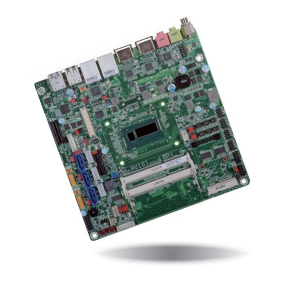
Chapter 2 Chapter 2 - Hardware Installation Important: Board Layout Electrostatic discharge (ESD) can damage your board, processor, disk drives, add-in boards, and other components. Perform installation procedures at an ESD workstation only. If such a station is not available, you can provide some ESD protection by wear- ing an antistatic wrist strap and attaching it to a metal part of the system chassis. -
Page 10: Installing The Dimm Module
Chapter 2 The system board supports the following memory interface. Installing the DIMM Module Single Channel (SC) Note: The system board used in the following illustrations may not resemble the actual Data will be accessed in chunks of 64 bits (8B) from the memory channels. board. -
Page 11: Jumper Settings
Chapter 2 Jumper Settings 5. Grasping the module by its edges, align the module into the socket at an approximately 30 degrees angle. Apply firm even pressure to each end of the module until it slips down into the socket. The contact fingers on the edge of the module will almost completely disappear Clear CMOS Data inside the socket. -
Page 12: Auto Power-On Select
Chapter 2 Auto Power-on Select USB Power Select USB 2-3 1-2 On: (JP14) Power-on via power button (default) 1-2 On: +5V JP25 (default) USB 7-8 (JP29) 2-3 On: USB 0-1 Power-on via AC power (JP15) 2-3 On: +5V_standby USB 9-10 USB 4-5 (JP27) (JP11) -
Page 13: Com 1/Com 2 Rs232/422/485 Select
Chapter 2 COM 1/COM 2 RS232/422/485 Select COM 1/ COM 2 COM 1/COM 2: RS232/422/485 COM 1 COM 2 RS422 RS232 RS485 Full Duplex JP10 JP3 (for COM 1) / JP7 (for COM 2) 3-4 On: RS422 5-6 On: RS485 1-2 On: RS232 Full Duplex (default) -
Page 14: Com 1/Com 2 Rs232/Power Select
Chapter 2 COM 1/COM 2 RS232/Power Select LCD/Inverter Power Select COM 1/COM 2: RS232/422/485 COM 1 COM 2 1-3 (RI), 2-4 (DCD) On: RS232 (default) 1-2 On: +12V JP19 3-5 (+5V), 4-6 (+12V) On: 2-3 On: +5V (default) RS232 with power JP9 is used to select the power level of the LCD/inverter power connector. -
Page 15: Digital I/O Power Select
Chapter 2 Digital I/O Power Select Digital I/O Output State 1-2 On: +5V_standby 1-2 On: +5V or +5V_standby DIO 4-7 (default) (JP22) JP23 DIO 0-3 2-3 On: +5V (default) (JP21) 2-3 On: GND JP23 is used to select the power of DIO (Digital I/O) signal. Based on the power level of DIO (Digital I/O) selected on JP23, JP21 (DIO pin 0-3) and JP22 (DIO pin 4-7) are used to select the state of DIO output: pull high or pull low. -
Page 16: Panel Power Select
Chapter 2 Panel Power Select LVDS Channel and bpp Select 1 On: Single LVDS 1-2 On: +12V 1 Off: Dual LVDS 3-4 On:+5V 2 On: VESA (24bpp) JP18 5-6 On: +3.3V 2 Off: JEIDA or VESA (default) (18bpp) Switch 1 allows you to select the LVDS channel and the color of bits per pixel. JP18 is used to select the power supplied with the LVDS LCD panel. -
Page 17: Ps/2 Keyboard/Mouse Power Select
Chapter 2 PS/2 Keyboard/Mouse Power Select Mini PCIe Signal Select 1-2 On: +5V (default) 2-3 On: +5V_standby 1-2 On: PCIe (default) JP17 2-3 On: mSATA JP2 is used to select the power of the PS/2 keyboard/mouse port. Selecting +5V_standby will JP17 is used to select the Mini PCIe signal: PCIe or mSATA. -
Page 18: Sata Dom Power Select
Chapter 2 SATA DOM Power Select SATA 0 JP20 1-2 On: GND (default) 2-3 On: +5V JP20 is used to select the power level of SATA DOM. Note: SATA port 0 provides adequate space for SATA DOM. Chapter 2 Hardware Installation... -
Page 19: Rear Panel I/O Ports
Chapter 2 Rear Panel I/O Ports Graphics Interfaces The display ports consist of the following: • 2 HDMI ports USB 2.0 USB 3.0 Mic-in HDMI 1 HDMI 2 HDMI 1 Line-out LAN 2 LAN 1 HDMI 1 HDMI 2 HDMI 2 The rear panel I/O ports consist of the following: •... -
Page 20: Rj45 Lan Ports
Chapter 2 RJ45 LAN Ports Audio Line-out Line-out Mic-in Mic-in LAN 2 LAN 1 LAN 2 LAN 1 Front Audio Features • Intel I210 PCI Express Gigabit Ethernet controller ® • Intel I218 with iAMT9.5 Gigabit Ethernet Phy ® Rear Audio The LAN ports allow the system board to connect to a local area network by means of a network hub. -
Page 21: Usb Ports
Chapter 2 USB Ports USB 2-3 Port Pins Pin Assignment Pins Pin Assignment USB3.0_PW3-4 (5V/5VSB) USB3_RX3_N_A USB3_RX3_P_A USB3_TX3_N_A USB3_TX3_P_A SBD2- SBD2+ USB 2.0 SBD3+ SBD3- USB 8 USB3_TX4_P_A USB 7 USB 2-3 USB3_TX4_N_A USB 1 USB3_RX4_P_A USB3_RX4_N_A USB 0 USB 3.0 USB3.0_PW3-4 (5V/5VSB) USB 3.0 USB 9-10... -
Page 22: I/O Connectors
Chapter 2 I/O Connectors Power Connector Digital I/O Connector Digital I/O Power Connector +12V Ground +12V Ground +12V Power Digital I/O Digital I/O power Use a power supply that complies with the +12V Power Supply Design Guide Version 1.1. The The 8-bit Digital I/O connector provides powering-on function to external devices that are con- 4-pin +12V power connector enables the delivery of +12VDC current to the processor’s Volt- nected to the connector. -
Page 23: Sata (Serial Ata) Connectors
Chapter 2 SATA (Serial ATA) Connectors SATA (Serial ATA) Power Connectors SATA Power 1 SATA 0 SATA 1 SATA 2 SATA SATA SATA 3.0 6Gb/s Power 0 Power 2 Features • 3 Serial ATA 3.0 ports with data transfer rate up to 6Gb/s •... -
Page 24: Com (Serial) Ports
Chapter 2 COM (Serial) Ports BIOS Setting Configure the serial COM ports in the Advanced menu (“Super IO Configuration” submenu) of the BIOS. Refer to the chapter 3 for more information. COM 2 COM 3 COM 1/COM 2: COM 3/COM 4: RS232/422/485 RS232 Note:... -
Page 25: Front Panel Connector
Chapter 2 Front Panel Connector Cooling Fan Connectors CPU Fan Ground Speed Control Power Sense PWR-BTN PWR-LED System Fan 2 Ground Front Power Panel Sense System Fan 1 RESET-SW HDD-LED HDD-LED - HDD LED This LED will light when the hard drive is being accessed. The fan connectors are used to connect cooling fans. -
Page 26: Lvds Lcd Panel Connector
Panel Power Panel Power BIOS Setting Configure the LCD panel in the Advanced/Chipset Features submenu of the BIOS. Refer to chapter 3 for more information. Note: DFI board's LVDS connector: Hirose DF13-40DP-1.25V(91)/40P/1.25mm; cable side connector: Hirose DF13-40DS-1.25C. Chapter 2 Hardware Installation... -
Page 27: Ps/2 Keyboard/Mouse Connector
Chapter 2 PS/2 Keyboard/Mouse Connector Wake-On-PS/2 Keyboard/Mouse The Wake-On-PS/2 Keyboard/Mouse function allows you to use the PS/2 keyboard or PS/2 mouse to power-on the system. To use this function: PS/2 KB/MS • Jumper Setting JP2 must be set to “2-3 On: 5V_standby”. Refer to “PS/2 Keyboard/Mouse Power Select” in this chapter for more information. -
Page 28: Edp Connector (Optional)
The system board used in the following illustrations may not resemble the actual one. These illustrations are for reference only. The EXT-DP card is connected to the HU101 motherboard via two cables. The photos below illustrates how to connect the extension module to the motherboard. -
Page 29: S/Pdif Connector
Chapter 2 S/PDIF Connector SMBus Connector S/PDIF SMBUS_Alert# SMBus SMBUS_Data SMBUS_CLK +3.3V_standby The S/PDIF connector is used to connect an external S/PDIF port. Your S/PDIF port may be The SMBus (System Management Bus) connector is used to connect SMBus devices. It is a mounted on a card-edge bracket. -
Page 30: Expansion Slots
Chapter 2 Expansion Slots Chassis Intrusion Connector Chassis Intrusion Mini PCI Express PCI Express x1 The board supports the chassis intrusion detection function. Connect the chassis intrusion PCI Express x1 Slot sensor cable from the chassis to this connector. When the system’s power is on and a chassis Install PCI Express cards such as network cards or other cards that comply to the PCI Express intrusion occurred, an alarm will sound. -
Page 31: Standby Power Led
Chapter 2 Standby Power LED Battery Standby Power LED Battery +3.3V This LED will lit red when the system is in the standby mode. It indicates that there is power on the system board. Power-off the PC and then unplug the power cord prior to installing any devices. -
Page 32: Chapter 3 - Bios Setup
Chapter 3 Chapter 3 - BIOS Setup Legends Overview Keys Function The BIOS is a program that takes care of the basic level of communication between the CPU and peripherals. It contains codes for various advanced features found in this system board. Right and Left arrows Moves the highlight left or right to select a menu. -
Page 33: Ami Bios Setup Utility
Chapter 3 AMI BIOS Setup Utility Advanced The Advanced menu allows you to configure your system for basic operation. Some entries are Main defaults required by the system board, while others, if enabled, will improve the performance of your system or let you set some features according to your preference. The Main menu is the first screen that you will see when you enter the BIOS Setup Utility. - Page 34 Chapter 3 ACPI Settings Trusted Computing This section is used to configure the system ACPI parameters. This section configures settings relevant to Trusted Computing innovations. Aptio Setup Utility - Copyright (C) 2012 American Megatrends, Inc. Aptio Setup Utility - Copyright (C) 2012 American Megatrends, Inc. Advanced Advanced Confi...
- Page 35 Chapter 3 CPU Configuration SATA Configuration This section is used to configure the CPU. It will also display the detected CPU information. This section is used to configure the settings of SATA device. Aptio Setup Utility - Copyright (C) 2012 American Megatrends, Inc. Aptio Setup Utility - Copyright (C) 2012 American Megatrends, Inc.
- Page 36 Chapter 3 Intel(R) Rapid Start Technology Entry on S3 RTC Wake This section is used to enable or disable the Intel Rapid Start Technology. This field is used to enable or disable the rapid start invocation upon S3 RTC wake. Entry After Aptio Setup Utility - Copyright (C) 2012 American Megatrends, Inc.
- Page 37 Chapter 3 AMT Configuration USB Configuration This section configures the parameters of Active Management Technology. This section is used to configure the parameters of the USB device. Aptio Setup Utility - Copyright (C) 2012 American Megatrends, Inc. Aptio Setup Utility - Copyright (C) 2012 American Megatrends, Inc. Advanced Advanced Enable/ Disable Intel(R)
- Page 38 Chapter 3 PCH-FW Configuration NCT6106D Super IO Configuration This section only displays the parameters of Management Engine Technology. This section is used to configure the I/O functions supported by the onboard Super I/O chip. Aptio Setup Utility - Copyright (C) 2012 American Megatrends, Inc. Aptio Setup Utility - Copyright (C) 2012 American Megatrends, Inc.
- Page 39 Chapter 3 Serial Port Aptio Setup Utility - Copyright (C) 2012 American Megatrends, Inc. Advanced Enables or disables the serial COM port. Serial Port 2 Confi guration Enable or Disable Serial Port (COM) Change Settings [Enabled] Serial Port Device Settings IO=2F8h;...
- Page 40 Chapter 3 CPU Smart Fan Control NCT6106D HW Monitor When this feature is set to Automatic, the CPU’s fan speed will rotate according to the This section displays the hardware health monitor. CPU’s temperature. The higher the temperature, the faster the speed of rotation. Aptio Setup Utility - Copyright (C) 2012 American Megatrends, Inc.
- Page 41 Chapter 3 Aux Fan Mode Power Failure Control Selects the Aux fan’s mode. The options are Thermal CruiseTM Mode, Fan Speed This section configures the status control when the power failure occurs. CruiseTM Mode and SmartFan TM IV Mode. AuxFan Target Temp Aptio Setup Utility - Copyright (C) 2012 American Megatrends, Inc.
- Page 42 Chapter 3 WatchDog Configuration Network Stack This section sets the system watchdog parameters. This section is used to enable or disable UEFI network stack. Aptio Setup Utility - Copyright (C) 2012 American Megatrends, Inc. Aptio Setup Utility - Copyright (C) 2012 American Megatrends, Inc. Advanced Advanced Network Stack...
- Page 43 Chapter 3 Ipv4 PXE Support Intel(R) Ethernet Connection I218-LM - 88:88:88:88:87:88... When enabled, Ipv4 PXE boot supports. When disabled, Ipv4 PXE boot option will not This section is used to configure the parameters of the Gigabit Ethernet device. be created. Ipv6 PXE Support Aptio Setup Utility - Copyright (C) 2012 American Megatrends, Inc.
- Page 44 Chapter 3 NIC Configuration Intel(R) I210 Gigabit Network Connection - 00:01:29:50... This field is used to configure the Boot Protocol, Wake on LAN, Link Speed and VLAN. This section is used to configure the parameters of the Gigabit Ethernet device. Aptio Setup Utility - Copyright (C) 2012 American Megatrends, Inc.
-
Page 45: Chipset
Chapter 3 Chipset NIC Configuration This field is used to configure the Boot Protocol, Wake on LAN, Link Speed and VLAN. This section configures relevant chipset functions. Aptio Setup Utility - Copyright (C) 2012 American Megatrends, Inc. Aptio Setup Utility - Copyright (C) 2012 American Megatrends, Inc. Main Advanced Chipset... - Page 46 Chapter 3 PCH-IO Configuration PCI Express Configuration This section illustrates the PCH parameters. This field is used to configure the PCI Express settings. Aptio Setup Utility - Copyright (C) 2012 American Megatrends, Inc. Aptio Setup Utility - Copyright (C) 2012 American Megatrends, Inc. Chipset Chipset Intel PCH RC Version...
- Page 47 Chapter 3 ASPM Support USB Configuration Sets the ASPM support. This field is used to configure the USB settings. Force L0s Force all links to the L0s state Aptio Setup Utility - Copyright (C) 2012 American Megatrends, Inc. Auto BIOS auto configure Chipset Disabled Disable the ASPM support...
- Page 48 Chapter 3 System Agent (SA) Configuration Graphics Configuration This section is used to configure the parameters of System Agent. This field configures the graphics settings. Aptio Setup Utility - Copyright (C) 2012 American Megatrends, Inc. Aptio Setup Utility - Copyright (C) 2012 American Megatrends, Inc. Chipset Chipset System Agent Bridge Name...
- Page 49 Chapter 3 DVMT Pre-Allocated LCD Control Selects DVMT 5.0 Pre-Allocated (Fixed) Graphics Memory size used by the Internal This field configures the LCD control. Graphics Device. Please refer to the information shown below. Aptio Setup Utility - Copyright (C) 2012 American Megatrends, Inc. Aptio Setup Utility - Copyright (C) 2012 American Megatrends, Inc.
- Page 50 Chapter 3 Memory Configuration Active LVDS This field only displays the memory configuration. Enables or disables the LVDS function. Aptio Setup Utility - Copyright (C) 2012 American Megatrends, Inc. Chipset Memory Information Memory RC Version 1.7.0.0 Memory Frequency 1600 Mhz Total Memory 12288 MB (DDR3) Memory Voltage...
-
Page 51: Boot
Chapter 3 Boot CSM Parameters Aptio Setup Utility - Copyright (C) 2012 American Megatrends, Inc. Aptio Setup Utility - Copyright (C) 2012 American Megatrends, Inc. Boot Main Advanced Chipset Boot Security Save & Exit Boot Confi guration This option controls if Number of seconds to Launch CSM [Enabled]... -
Page 52: Security
Chapter 3 Security Save & Exit Aptio Setup Utility - Copyright (C) 2012 American Megatrends, Inc. Aptio Setup Utility - Copyright (C) 2012 American Megatrends, Inc. Main Advanced Chipset Boot Security Save & Exit Main Advanced Chipset Boot Security Save & Exit Save Changes and Exit Exit system setup after Password Description... -
Page 53: Updating The Bios
Chapter 3 Updating the BIOS Save as User Defaults To save changes done so far as user default, select this field and then press <Enter>. To update the BIOS, you will need the new BIOS file and a flash utility, AFUDOS.EXE. Please A dialog box will appear. -
Page 54: Notice: Bios Spi Rom
Chapter 3 Notice: BIOS SPI ROM 1. The Intel Management Engine has already been integrated into this system board. Due to ® the safety concerns, the BIOS (SPI ROM) chip cannot be removed from this system board and used on another system board of the same model. 2. -
Page 55: Chapter 4 - Supported Software
Install drivers, utilities and software applications that are required to facilitate and enhance the performance of the system board. You may acquire the software from your sales representa- tives, from an optional DVD included in the shipment, or from the website download page at https://www.dfi.com/DownloadCenter. For Windows 8 Note: This step can be ignored if the applications are standalone files. - Page 56 Chapter 4 Intel Chipset Software Installation Utility 3. Go through the readme document for more installa- tion tips then click Next. The Intel Chipset Software Installation Utility is used for updating Windows INF files so that ® the Intel chipset can be recognized and configured properly in the system. To install the utility, click “Intel Chipset Software Installation Utility”...
- Page 57 Chapter 4 Intel HD Graphics Drivers 3. Go through the readme document for system re- quirements and installation To install the driver, click “Intel HD Graphics Drivers” on the main menu. tips then click Next. 1. Setup is now ready to install the graphics driver.
- Page 58 Chapter 4 Intel Management Engine Drivers 9.5 3. Setup is currently installing the driver. After installation has com- pleted, click Next. To install the driver, click “Intel Management Engine Drivers 9.5” on the main menu. 1. Setup is ready to install the driver. Click Next.
- Page 59 Chapter 4 Audio Drivers Intel LAN Drivers To install the driver, click “Audio Drivers” on the main menu. To install the driver, click “Intel LAN Drivers” on the main menu. 1. Setup is ready to install the 1. Setup is ready to install the driver.
- Page 60 DFI Utility 4. Click Install to begin the installation. DFI Utility provides information about the board, Watchdog,and DIO. To access the utility, click “DFI Utility” on the main menu. Note: If you are using Windows 7, you need to access the operating system as an administrator to be able to install the utility.
- Page 61 Chapter 4 3. Enter “User name” (SB102) The DFI Utility icon will appear on the desktop. Double-click the icon to open the utility. and “Organization” information then click “Next”. 4. Click “Install” to begin the installation. Information 5. After completing installa tion, click “Finish”.
- Page 62 Chapter 4 HW Health Set WatchDog Chapter 4 Supported Software www.dfi .com...
- Page 63 Chapter 4 Microsoft Framework 4.5 3. After completing installation, click Finish. To install the utility, click “Microsoft Framework 4.5” on the main menu. 1. Read and accept the license agree- ment. Then, click “Installation“. 2. Setup is installing the driver. Chapter 4 Supported Software www.dfi...
- Page 64 Chapter 4 Intel USB 3.0 Drivers (For Windows 7 Only) 3. Go through the readme docu- ment for more installation tips then click Next. To install the driver, click “Intel USB 3.0 Driver” on the main menu. 1. Setup is ready to install the driver. Click Next.
- Page 65 Chapter 4 Intel Dynamic Platform and Thermal Framework 8.0 3. After the setup progress finishes, click Next to continue.. The Intel Dynamic Platform and Thermal Framework Technology enables the control of power and temperature management for the system protection. To install the driver, click “Intel Dynamic Platform and Thermal Framework 8.0” on the main menu.
- Page 66 Chapter 4 Intel Rapid Storage Technology 3. Read the license agreement then click Yes. The Intel Rapid Storage Technology is a utility that allows you to monitor the current status of the SATA drives. It enables enhanced performance and power management for the storage subsystem.
- Page 67 Chapter 4 Intel Rapid Start Technology 6. Click “Yes, I want to restart my computer now” then click Finish. The Intel Rapid Start Technology is a utility that allows your system to wake up and run faster. Restarting the system will allow the To install the driver, click “Intel Rapid Start Technology”...
- Page 68 Chapter 4 F6 Floppy (For Windows 7 Only) Infineon TPM Driver and Tool (optional) This is used to create a floppy driver diskette needed when you install Windows® XP using To install the driver, click “Infineon TPM driver and tool (option)” on the main menu. the F6 installation method.
- Page 69 Chapter 4 Enter the necessary information and TPM requires installing the Microsoft then click Next. Visual C++ package prior to install- ing the utility. Click Install. Select a setup type and then click The setup program is currently Next. installing the Microsoft Visual C++ package.
- Page 70 Chapter 4 Adobe Acrobat Reader 9.3 10. Click “Yes“ to restart your system. To install the reader, click “Adobe Acrobat Reader 9.3” on the main menu. 1. Click Next to install or click Change Destination Folder to select another folder. 2.
-
Page 71: Chapter 5 - Digital I/O Programming Guide
Chapter 5 Chapter 5 - Digital I/O Programming Guide The Configuration Register (register 3) configures the direction of the I/O pins. If a bit in this register is set to 1, the corresponding port pin is enabled as an input with a high-impedence Register Description output driver. - Page 72 Chapter 5 Function Description GPIO Output Process I2CWriteByte(SlaveAddr, SubAddr, Data): #defi ne SLAVE_ADDR 0x42 Write a Byte data to a specified I2C Device. #defi ne INPUT_PORT 0x00 #defi ne OUTPUT_PORT 0x01 I2CReadByte(SlaveAddr, SubAddr, *Data): 0x02 #defi ne INVERSION_PORT Read a Byte data from a specified I2C Device. 0x03 #defi...
-
Page 73: Chapter 6 - Raid
Chapter 6 Chapter 6 - RAID Settings The system board allows configuring RAID on Serial ATA drives. It supports RAID 0, RAID 1, To enable the RAID function, the following settings are required. RAID 5 and RAID 10. 1. Connect the Serial ATA drives. RAID Levels 2. - Page 74 Chapter 6 Step 4: Install the RAID Driver During OS Installation Step 5: Install the Intel Rapid Storage Technology Utility The RAID driver must be installed during the Windows XP or Windows 2000 installation us- The Intel Rapid Storage Technology Utility can be installed from within Windows. It allows ®...
- Page 75 Chapter 6 5. Go through the readme 8. Click “Yes, I want to restart document to view system this computer now” to requirements and installa- complete the installation tion information then click and then click Finish. Next. 6. Click Next to install to the default folder or click change to choose another destination folder.
-
Page 76: Chapter 7 - Intel Amt Settings
Chapter 7 Chapter 7 - Intel AMT Settings Enable Intel AMT in the AMI BIOS ® Overview 1. Power-on the system then press <Del> to enter the main menu of the AMI BIOS. Intel Active Management Technology (Intel AMT) combines hardware and software solution to ®... -
Page 77: Extension (Mebx) Screen
Chapter 7 Enable Intel AMT in the Intel Management 4. In the Save & Exit menu, select Save Changes and Reset then select OK. ® ® Engine BIOS Extension (MEBX) Screen Aptio Setup Utility - Copyright (C) 2012 American Megatrends, Inc. Main Advanced Chipset... - Page 78 Chapter 7 3. Enter a new password in the space provided under Intel(R) ME New Password then press 4. You will be asked to verify the password. Enter the same new password in the space pro- Enter. The password must include: vided under Verify Password then press Enter.
- Page 79 Chapter 7 6. Select Change Intel(R) ME Password then press Enter. Select Local FW Update then press Enter. Select Enabled then press Enter. You will be prompted for a password. The default password is “admin”. Enter the default password in the space provided under Intel(R) ME New Password then press Enter. Intel(R) Management Engine BIOS Extension v9.0.0.0029/Intel(R) ME v9.5.30.1808 Copyright(C) 2003-13 Intel Corporation.
- Page 80 Chapter 7 In the Intel(R) AMT Configuration menu, select Manageability Feature Selection In the SOL/IDER/KVM menu, select Username and Password then press Enter. then press Enter. Select Disabled then press Enter. Select Disabled then press Enter. Intel(R) Management Engine BIOS Extension v9.0.0.0029/Intel(R) ME v9.5.30.1808 Intel(R) Management Engine BIOS Extension v9.0.0.0029/Intel(R) ME v9.5.30.1808 Copyright(C) 2003-13 Intel Corporation.
- Page 81 Chapter 7 In the SOL/IDER/KVM menu, select IDER then press Enter. Select Disabled then In the SOL/IDER/KVM menu, select Legacy Redirection Mode then press Enter. press Enter. Intel(R) Management Engine BIOS Extension v9.0.0.0029/Intel(R) ME v9.5.30.1808 Intel(R) Management Engine BIOS Extension v9.0.0.0029/Intel(R) ME v9.5.30.1808 Copyright(C) 2003-13 Intel Corporation.
- Page 82 Chapter 7 Select Previous Menu until you return to the Intel(R) AMT Configuration menu. Select In the User Consent menu, select Opt-in Configurable from Remote IT then press User Consent then press Enter. Enter. Select Disable Remote Control of KVM Opt-in Policy then press Enter. Intel(R) Management Engine BIOS Extension v9.0.0.0029/Intel(R) ME v9.5.30.1808 Intel(R) Management Engine BIOS Extension v9.0.0.0029/Intel(R) ME v9.5.30.1808 Copyright(C) 2003-13 Intel Corporation.
- Page 83 Chapter 7 In the Intel(R) AMT Configuration menu, select Network Setup then press Enter. In the Intel(R) ME Network Name Settings menu, select Host Name then press Enter. Enter the computer’s host name then press Enter. Intel(R) Management Engine BIOS Extension v9.0.0.0029/Intel(R) ME v9.5.30.1808 Intel(R) Management Engine BIOS Extension v9.0.0.0029/Intel(R) ME v9.5.30.1808 Copyright(C) 2003-13 Intel Corporation.
- Page 84 Chapter 7 Select Shared/Dedicated FQDN then press Enter. Select Shared or Dedicated then Select Previous Menu until you return to the Intel(R) ME Network Setup menu. Select press Enter. TCP/IP Settings then press Enter. Intel(R) Management Engine BIOS Extension v9.0.0.0029/Intel(R) ME v9.5.30.1808 Intel(R) Management Engine BIOS Extension v9.0.0.0029/Intel(R) ME v9.5.30.1808 Copyright(C) 2003-13 Intel Corporation.
- Page 85 Chapter 7 In the Intel(R) AMT Configuration menu, select Unconfigure Network Access then In the Intel(R) Remote Setup And Configuration menu, select Current Provisioing press Enter. Mode then press Enter. Intel(R) Management Engine BIOS Extension v9.0.0.0029/Intel(R) ME v9.5.30.1808 Intel(R) Management Engine BIOS Extension v9.0.0.0029/Intel(R) ME v9.5.30.1808 Copyright(C) 2003-13 Intel Corporation.
- Page 86 Chapter 7 In the Intel(R) AMT Configuration menu, select Power Control then press Enter. In the Intel(R) AMT Power Control menu, select Idle Timeout then press Enter. Enter the timeout value (1-65535). Intel(R) Management Engine BIOS Extension v9.0.0.0029/Intel(R) ME v9.5.30.1808 Intel(R) Management Engine BIOS Extension v9.0.0.0029/Intel(R) ME v9.5.30.1808 Copyright(C) 2003-13 Intel Corporation.
-
Page 87: Appendix A - Troubleshooting
Appendix A Appendix A - NLITE and AHCI Installation Guide 4. Insert the XP installation disc into an optical drive. nLite 5. Launch nLite. The Welcome screen will appear. Click nLite is an application program that allows you to customize your XP installation disc by Next. - Page 88 Appendix A 7. Click Next. 9. Click Insert and then select Multiple driver folder to select the drivers you will integrate. Click Next. Select only the drivers ap- 8. In the Task Selection dialog propriate for the Windows box, click Drivers and version that you are using Bootable ISO.
- Page 89 Appendix A If you are uncertain of The program is currently the southbridge chip used integrating the drivers on your motherboard, and applying changes to select all RAID/AHCI the installation. controllers and then click When the program is finished applying the changes, click Next.
- Page 90 Appendix A To create an image, You have finished cus- select the Create Image tomizing the Windows mode under the General XP installation disc. Click section and then click Finish. Next. Enter the BIOS utility to configure the SATA con- troller to RAID/AHCI.
- Page 91 Appendix A AHCI 5. In the Hardware Update Wizard dialog box, select “No, not this time” then The installation steps below will guide you in configuring your SATA drive to AHCI mode. click Next. 1. Enter the BIOS utility and configure the SATA controller to IDE mode. 2.
- Page 92 Appendix A A warning message 8. Click “Have Disk”. appeared because the se- lected SATA controller did not match your hardware device. Ignore the warning and click Yes to proceed. Click Finish. 9. Select C:\AHCI\iaAHCI.inf and then click Open. The system’s settings have been changed.
-
Page 93: Appendix B - Watchdog Sample Code
Appendix B Appendix B - Watchdog Sample Code ;Software programming example: ;--------------------------------------------- ;(1) Enter Super IO Confi guration mode ;--------------------------------------------- DX,4EH AL,87H DX,AL DX,AL ;------------------------------------------------------------------------------------------- ;(2) Confi guration Logical Device 8, register CRF0/CRF1 (WDT Control/WDT timer) ;------------------------------------------------------------------------------------------- DX,4EH AL,07H ;Ready to Program Logical Device DX,AL DX,4FH AL,08H... -
Page 94: Appendix C - System Error Message
Appendix C Appendix C - System Error Message Hard Disk(s) fail (20) When the BIOS encounters an error that requires the user to correct something, either a beep HDD initialization error. code will sound or a message will be displayed in a box in the middle of the screen and the message, PRESS F1 TO CONTINUE, CTRL-ALT-ESC or DEL TO ENTER SETUP, will be shown in Hard Disk(s) fail (10) the information box at the bottom. -
Page 95: Appendix D - Troubleshooting
Appendix D Appendix D - Troubleshooting Checklist The picture seems to be constantly moving. Troubleshooting Checklist 1. The monitor has lost its vertical sync. Adjust the monitor’s vertical sync. 2. Move away any objects, such as another monitor or fan, that may be creating a magnetic This chapter of the manual is designed to help you with problems that you may encounter field around the display. - Page 96 Appendix D Hard Drive System Board 1. Make sure the add-in card is seated securely in the expansion slot. If the add-in card is Hard disk failure. loose, power off the system, re-install the card and power up the system. 1.
Need help?
Do you have a question about the HU101 and is the answer not in the manual?
Questions and answers