Table of Contents
Advertisement
Quick Links
Advertisement
Table of Contents

Related Manuals for DFI HR900-B


Summary of Contents for DFI HR900-B
- Page 1 HR900-B COM Express Board User’s Manual A16560217...
-
Page 2: Copyright
Copyright This publication contains information that is protected by copyright. No part of it may be reproduced in any form or by any means or used to make any transfor- mation/adaptation without the prior written permission from the copyright hold- ers. -
Page 3: Fcc And Doc Statement On Class B
FCC and DOC Statement on Class B This equipment has been tested and found to comply with the limits for a Class B digital device, pursuant to Part 15 of the FCC rules. These limits are designed to provide reasonable protection against harmful interference when the equipment is operated in a residential installation. -
Page 4: Table Of Contents
����������������������������������������������������������������������������� 19 Clear CMOS Data ��������������������������������������������������������������������� 19 Connectors ���������������������������������������������������������������������������������� 20 CPU Fan Connector ������������������������������������������������������������������� 20 COM Express Connectors ���������������������������������������������������������� 21 PIN Mapping ���������������������������������������������������������������������������� 26 Standby Power LED ���������������������������������������������������������������������� 28 Cooling Option ....................Installing HR900-B onto a Carrier Board ���������������������������������������� 32... - Page 5 Introduction Chapter 3 - BIOS Setup ������������������������������������������������������������������ 37 Overview ������������������������������������������������������������������������������������ 37 AMI BIOS Setup Utility ����������������������������������������������������������������� 39 Main ��������������������������������������������������������������������������������������� 39 Advanced �������������������������������������������������������������������������������� 40 Chipset ����������������������������������������������������������������������������������� 53 Boot ��������������������������������������������������������������������������������������� 60 Security ���������������������������������������������������������������������������������� 61 Save&Exit ������������������������������������������������������������������������������� 62 Updating the BIOS ������������������������������������������������������������������������ 63 Chapter 4 - Supported Software ���������������������������������������������������...
-
Page 6: About This Manual
Introduction About this Manual An electronic file of this manual is included in the CD. To view the user’s manual in the CD, insert the CD into a CD-ROM drive. The autorun screen (Main Board Utility CD) will appear. Click “User’s Manual” on the main menu. Warranty 1. -
Page 7: Static Electricity Precautions
Introduction Static Electricity Precautions It is quite easy to inadvertently damage your PC, system board, components or devices even before installing them in your system unit. Static electrical dis- charge can damage computer components without causing any signs of physical damage. -
Page 8: About The Package
Introduction About the Package The package contains the following items. If any of these items are missing or damaged, please contact your dealer or sales representative for assistance. One HR900-B board One heat sink One drivers/utilities disk ... -
Page 9: Chapter 1 - Introduction
Introduction Chapter 1 - Introduction Specifications Processor • Socket G2 988B for: - Intel Core™ i7-2710QE (6M Cache, up to 3.0 GHz); 45W ® - Intel Core™ i5-2510E (3M Cache, up to 3.1 GHz); 35W ® - Intel Core i3-2330E (2.2GHz, 35W, PGA) ®... - Page 10 Introduction Expansion • Supports 8 USB ports (USB 1.1/2.0 host controllers) Interfaces • Supports 4 PCI slots (PCI 2.3 interface) • Supports PCIe x16 / SDVO / HDMI / Display Port switchable interface - Uses QM67’s DDI (Digital Display Interface) Port B for SDVO/ HDMI and DDI Port C for display Port/ HDMI - VBIOS default setting at Port C only; VBIOS settings modified upon request • Supports 1 PCIE x16 Gen2 interface • Supports 5 PCIE x1 interfaces • Supports LPC interface • Supports IDE interface • Supports 8-bit Digital I/O Damage Free • Monitors CPU temperature and overheat alarm Intelligence • Monitors CPU fan speed and failure alarm • Monitors Vcore/V /1.5V voltages and failure alarm • Watchdog timer function BIOS • 64Mbit SPI BIOS Temperature • 0 C to 60 Humidity • 10% to 90% Power • Input: 12V, 5VSB, VCC_RTC Regulatory • EMC: CE, FCC Part 15 Class B • Dimensions - Basic COM Express form factor - 95mm (3.74”) x 125mm (4.9”) • Compliance - PICMG COM Express R1.0 basic form factor, Type 2...
-
Page 11: Features
Introduction Features Watchdog Timer The Watchdog Timer function allows your application to regularly “clear” the sys- tem at the set time interval. If the system hangs or fails to function, it will reset at the set time interval so that your system will continue to operate. DDR3 DDR3 delivers increased system bandwidth and improved performance. -
Page 12: Chapter 2 - Hardware Installation
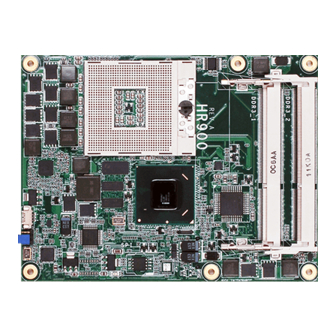
Hardware Installation Chapter 2 - Hardware Installation Board Layout Intel CPU fan QM67 Clear CMOS (JP1) SPI Flash Intel BIOS 82579LM Standby Power LED Top View D110 COM Express connector C110 B110 COM Express connector A110 Buttom View... -
Page 13: Mechanical Diagram
Hardware Installation Mechanical Diagram 4.08 4.08 0.00 0.00 87.00 87.00 91.08 91.08... -
Page 14: System Memory
Hardware Installation Important: Electrostatic discharge (ESD) can damage your board, processor, disk drives, add-in boards, and other components. Perform installation proce- dures at an ESD workstation only. If such a station is not available, you can provide some ESD protection by wearing an antistatic wrist strap and attaching it to a metal part of the system chassis. -
Page 15: Installing The Dim Module
Hardware Installation Installing the DIM Module Note: The system board used in the following illustrations may not resemble the actual one. These illustrations are for reference only. 1. Make sure the PC and all other peripheral devices connected to it has been powered down. - Page 16 Hardware Installation 5. Grasping the module by its edges, align the module into the socket at an ap- proximately 30 degrees angle. Apply firm even pressure to each end of the module until it slips down into the socket. The contact fingers on the edge of the module will almost completely disappear inside the socket.
-
Page 17: Cpu Overview
Hardware Installation Overview The system board is equipped with a surface mount rPGA 988B CPU socket. Note: The system board used in the following illustrations may not resemble the actual one. These illustrations are for reference only. Installing the CPU 1. - Page 18 Hardware Installation 5. Position the CPU above the socket. The gold triangular mark on the CPU must align with pin 1 of the CPU socket. Important: Handle the CPU by its edg- es and avoid touching the Gold triangular mark pins.
-
Page 19: Jumper Settings
Hardware Installation Jumper Settings Clear CMOS Data 2-3 On: 1-2 On: Normal Clear CMOS Data (default) If you encounter the following, a) CMOS data becomes corrupted. b) You forgot the supervisor or user password. you can reconfigure the system with the default values stored in the ROM BIOS. To load the default values stored in the ROM BIOS, please follow the steps below. -
Page 20: Connectors
Hardware Installation Connectors CPU Fan Connector Sense Power Ground Connect the CPU fan’s cable connector to the CPU fan connector on the board. The cooling fan will provide adequate airflow throughout the chassis to prevent overheating the CPU and board components. BIOS Setting “Module Board H/W Monitor”... -
Page 21: Com Express Connectors
Connect the COM Express connectors (lcoated on the solder side of the board) to the COM Express connectors on the carrier board. Refer to the “Installing HR900-B onto a Carrier Board” section for more informa- tion. - Page 22 Hardware Installation Row A GNDA1 PCIE_TX8- GBE0_MDI3- GBE0_MDI3+ PCIE_TX4+ GNE0_LINK100# PCIE_TX4- GBE0_LINK1000# GNDA7 GBE0_MDI2- PCIE_TX3+ GBE0_MDI2+ PCIE_TX3- GPI1(PCH GPIO3) GBE0_MDI1- PCIE_TX2+ GBE0_MDI1+ PCIE_TX2- GNDA2 GNDA8 GBE0_MDI0- GPI2(PCH GPIO4) GBE0_MDI0+ PCIE_TX1+ GBE0_CTREF PCIE_TX1- SUS_S3# GNDA9 SATA0_TX+ LVDS_A0+ SATA0_TX- LVDS_A0- SUS_S4# LVDS_A1+ SATA0_RX+ LVDS_A1- SATA0_RX-...
- Page 23 Hardware Installation Row B GNDB1 PCIE_RX8- GBE0_ACT# GPO2(PCH GPIO54) LPC_FRAME# PCIE_RX4+ LPC_AD0 PCIE_RX4- LPC_AD1 GNDB7 LPC_AD2 PCIE_RX3+ LPC_AD3 PCIE_RX3- LPC_DRQ0# GPO3(PCH GPIO55) LPC_DRQ1# PCIE_RX2+ LPC_CLK PCIE_RX2- GNDB2 WAKE0# PWRBTN# WAKE1# SMB_CK PCIE_RX1+ SMB_DAT PCIE_RX1- SMB_ALERT# GNDB8 SATA1_TX+ LVDS_B0+ SATA1_TX- LVDS_B0- SUS_STAT# LVDS_B1+ SATA1_RX+...
- Page 24 Hardware Installation Row C GNDC1 PEG_RX1-/SDVO_INT- IDE_D7 IDE_D6 PEG_RX2+/SDVO_STALL+ IDE_D3 PEG_RX2-/SDVO_STALL- IDE_D15 GNDC7 IDE_D8 PEG_RX3+/DDPB_HPD IDE_D9 PEG_RX3- IDE_D2 IDE_D13 IDE_D1 PEG_RX4+ GNDC2 PEG_RX4- IDE_D14 IDE_IORDY PEG_RX5+ IDE_IOR# PEG_RX5- PCI_PME# GNDC8 PCI_GNT2# PEG_RX6+/DDPC_AUX+ PCI_REQ2# PEG_RX6-/DDPC_AUX- PCI_GNT1# SDVOB_CTRLDATA PCI_REQ1# PEG_RX7+/DDPC_HPD PCI_GNT0# PEG_RX7- GNDC3 GNDC9 PCI_REQ0#...
- Page 25 Hardware Installation Row D GNDD1 PEG_TX1-/DDPB_1- IDE_D5 IDE_D10 PEG_TX2+/DDPB_2+ IDE_D11 PEG_TX2-/DDPB_2- IDE_D12 GNDD7 IDE_D4 PEG_TX3+/DDPB_3+ IDE_D0 PEG_TX3-/DDPB_3- IDE_REQ# IDE_IOW# IDE_ACK# PEG_TX4+/DDPC_0+ GNDD2 PEG_TX4-/DDPC_0- IDE_IRQ GNDD8 IDE_A0 PEG_TX5+/DDPC_1+ IDE_A1 PEG_TX5-/DDPC_1- IDE_A2 GNDD9 IDE_CS1# PEG_TX6+/DDPC_2+ IDE_CS3# PEG_TX6-/DDPC_2- IDE_RESET# SDVO_CLK PCI_GNT3# PEG_TX7+/DDPC_3+ PCI_REQ3# PEG_TX7-/DDPC_3- GNDD3 GNDD10...
-
Page 26: Pin Mapping
Hardware Installation PIN Mapping DDI Port B QM67 Digital Display Interface Signal (Port B) COM Express BTB Connector Pin No. SDVO HDMI/DVI DDPB_[0]P: red DDPB_[0]P: TMDSB_DATA2 DDPB_[0]N: red complement DDPB_[0]N: TMDSB_DATA2B DDPB_[1]P: green DDPB_[1]P: TMDSB_DATA1 DDPB_[1]N:green complement DDPB_[1]N: TMDSB_DATA1B DDPB_[2]P: blue DDPB_[2]P: TMDSB_DATA0 DDPB_[2]N: blue complement DDPB_[2]N: TMDSB_DATA0B... -
Page 27: Display Port
Hardware Installation DDI Port C QM67 Digital Display Interface Signal (Port C) COM Express BTB Connector Pin No. Display Port HDMI/DVI DDPC_[0]P: Display Port Lane 0 DDPC_[0]P: TMDSC_DATA2 DDPC_[0]N: Lane 0 complement DDPC_[0]N: TMDSC_DATA2B DDPC_[1]P: Display Port Lane 1 DDPC_[1]P: TMDSC_DATA1 DDPC_[1]N: Lane 1 complement DDPC_[1]N: TMDSC_DATA1B DDPC_[2]P: Display Port Lane 2... -
Page 28: Standby Power Led
Hardware Installation Standby Power LED Standby Power LED This LED will light when the system is in the standby mode. -
Page 29: Cooling Option
Top View of the Heat Sink Bottom View of the Heat Sink • “1” and “2” denote the locations of the thermal pads designed to contact the corresponding components that are on HR900-B. • Remove the plastic covering from the thermal pads prior to mounting the heat sink onto HR900-B. - Page 30 Hardware Installation Dimensions...
- Page 31 Hardware Installation...
-
Page 32: Installing Hr900-B Onto A Carrier Board
The carrier board used in this section is for reference purpose only and may not resemble your carrier board. These illustrations are mainly to guide you on how to install HR900-B onto the carrier board of your choice. 1. The photo below shows the locations of the mounting holes. -
Page 33: Hardware Installation
Hardware Installation 3. While supporting the mounting screw at the bottom, from the top side of the board, fasten a bolt into the screw. Bolts 4. The photo below shows the solder side of the board with the screws already fixed in place. Mounting screw... - Page 34 5. The photo below shows the component side of the board with the bolts al- ready fixed in place. Bolts 6. Position the heat sink on top of HR900-B with the heat sink’s mounting holes aligned with HR900-B’s mounting holes. Insert one of the provided long screws into the mounting hole shown in the photo below.
- Page 35 7. From the bottom of the board, fasten the provided bolt into the screw and then connect the cooling fan’s cable to the fan connector on HR900-B. Fan connector Bolt 8. Grasping HR900-B by its edges, position it on top of the carrier board with its mounting holes aligned with the bolts on the carrier board. This will also align the COM Express connectors of the two boards to each other. COM Express connectors...
- Page 36 Hardware Installation 9. Press HR900-B down firmly until it is completely seated on the COM Express connectors of the carrier board. HR900-B Carrier board 10. Use the provided mounting screws to secure HR900-B with heat sink to the carrier board. The photo below shows the locations of the long/short mount- ing screws.
-
Page 37: Chapter 3 - Bios Setup
BIOS Setup Chapter 3 - BIOS Setup Overview The BIOS is a program that takes care of the basic level of communication be- tween the CPU and peripherals. It contains codes for various advanced features found in this system board. The BIOS allows you to configure the system and save the configuration in a battery-backed CMOS so that the data retains even when the power is off. - Page 38 BIOS Setup Legends Keys Function Right and Left arrows Moves the highlight left or right to select a menu. Up and Down arrows Moves the highlight up or down between submenus or fields. <Esc> Exits to the BIOS Setup Utility. + (plus key) Scrolls forward through the values or options of the highlighted field.
-
Page 39: Ami Bios Setup Utility
BIOS Setup AMI BIOS Setup Utility Main The Main menu is the first screen that you will see when you enter the BIOS Setup Utility. Aptio Setup Utility - Copyright (C) 2010 American Megatrends, Inc. Main Advanced Chipset Boot Security Save &... -
Page 40: Advanced
BIOS Setup Advanced The Advanced menu allows you to configure your system for basic operation. Some entries are defaults required by the system board, while others, if enabled, will improve the performance of your system or let you set some features ac- cording to your preference. -
Page 41: Bios Setup
BIOS Setup ACPI Power Management Configuration This section is used to configure the ACPI Power Management. Aptio Setup Utility - Copyright (C) 2010 American Megatrends, Inc. Advanced ACPI Power Management Configuration Select the highest ACPI sleep state the system will [S3 (Suspend to RAM) ] ACPI Sleep State enter, when the SUSPEND... -
Page 42: Cpu Configuration
BIOS Setup CPU Configuration This section is used to configure the CPU. It will also display the detected CPU information. Aptio Setup Utility - Copyright (C) 2010 American Megatrends, Inc. Advanced CPU Configuration Enabled for Windows XP and Linux (OS optimized Intel (R) Core (TM) i7-2710QE CPU @ 2.10GHz for Hyper-Threading EMT64... -
Page 43: Sata Configuration
BIOS Setup SATA Configuration This section is used to configure SATA functions. Aptio Setup Utility - Copyright (C) 2010 American Megatrends, Inc. Advanced SATA Controller(s) [Enabled] Enable or disable SATA SATA Mode Selection [IDE] Device. Serial ATA Port 0 Empty Software Preserve Unknown Serial ATA Port 1... - Page 44 BIOS Setup PCH-FW Configuration Aptio Setup Utility - Copyright (C) 2010 American Megatrends, Inc. Advanced ME FW Version 7.0.2.1164 ME Firmware Mode Normal Mode ME Firmware Type Full Sku Firmware ME Firmware SKU 1.5MB Select Screen → ←: Select Item ↑↓: Enter: Select +/ -:...
-
Page 45: Usb Configuration
BIOS Setup USB Configuration This section is used to configure USB. Aptio Setup Utility - Copyright (C) 2010 American Megatrends, Inc. Advanced Enables Legacy USB USB Configuration support. AUTO option disables legacy support if USB Devices: no USB devices are 2 Hubs connected. - Page 46 BIOS Setup F75387 Module Board H/W Monitor Aptio Setup Utility - Copyright (C) 2010 American Megatrends, Inc. Advanced Enables CPU SmartFan === Module Board H/W Monitor === Current CPU Temperature : +52.0 C Vcore : +1.104 V VGFX : +0.448 V +1.5(V) : +1.520 V +3.3(V)
-
Page 47: Serial Port
BIOS Setup UART Configuration This section is used to configure the serial port functions. Aptio Setup Utility - Copyright (C) 2010 American Megatrends, Inc. Advanced UART Configuration Set Parameters of Serial Port 1 (COMA) Super IO Chip Fintek F81216 Serial Port 1 Configuration ... -
Page 48: Super Io Configuration
BIOS Setup Super IO Configuration This section is used to configure the I/O functions supported by the onboard Su- per I/O chip. Aptio Setup Utility - Copyright (C) 2010 American Megatrends, Inc. Advanced Super IO Configuration Restore AC Power Loss help. -
Page 49: Floppy Disk Controller
BIOS Setup Floppy Disk Controller Configuration Aptio Setup Utility - Copyright (C) 2010 American Megatrends, Inc. Advanced Floppy Disk Controller Configuration Enable or Disable Floppy Disk Controller [Enabled] Floppy Disk Controller Reset Required Device Settings Change Settings [Auto] Select Screen →... -
Page 50: Case Open Warning
BIOS Setup W83627H Carry Board H/W Monitor Aptio Setup Utility - Copyright (C) 2010 American Megatrends, Inc. Advanced Enable/Disable Case Open === Carry Board H/W Monitor === Warning Function Case Open Warning [Disabled] Current FAN1 Speed : N/A Current FAN2 Speed : N/A Current FAN3 Speed : 5443 RPM... -
Page 51: Watchdog Configuration
BIOS Setup Onboard ATA Controller Configuration Aptio Setup Utility - Copyright (C) 2010 American Megatrends, Inc. Advanced PATA Primary Master Not Present PATA Primary Slave Not Present Select Screen → ←: Select Item ↑↓: Enter: Select +/ -: Change Opt. General Help Previous Values Optimized Defaults... -
Page 52: Sandybridge Ppm Configuration
BIOS Setup Sandybridge PPM Configuration Aptio Setup Utility - Copyright (C) 2010 American Megatrends, Inc. Advanced Sandybridge PPM Configuration Enable/Disable Intel SpeedStep EIST [Enabled] Turbo Mode [Enabled] CPU C3 Report [Enabled] CPU C6 Report [Enabled] CPU C7 Report [Enabled] Select Screen →... -
Page 53: Chipset
BIOS Setup Chipset Configures relevant chipset functions. Aptio Setup Utility - Copyright (C) 2010 American Megatrends, Inc. Main Advanced Chipset Boot Security Save & Exit System Agent (SA) System Agent (SA) Configuration Parameters PCH-IO Configuration Select Screen ← →: Select Item ↑↓: Enter: Select... -
Page 54: Intel Igfx Configuration
BIOS Setup System Agent (SA) Configuration Aptio Setup Utility - Copyright (C) 2010 American Megatrends, Inc. Chipset System Agent RC Version 1.0.0.1 Configure Intel IGFX Supported Settings. VT-d Capability Intel IGFX Configuration NB PCIe Configuration Memory Configuration Select Screen →... -
Page 55: Aperture Size
BIOS Setup GTT Size Selects the GTT Size. The options are 1MB and 2 MB. Aperture Size This fi eld is relevant to the memory-mapped graphics data of the PCIe x16. Leave this in its default setting. DVMT Total Gfx Mem This fi... -
Page 56: Nb Pcie Configuration
BIOS Setup NB PCIe Configuration Aptio Setup Utility - Copyright (C) 2010 American Megatrends, Inc. Chipset NB PCIe Configuration Configure PEG0 Not Present B0: D1: F0 Gen1-Gen2 PEG0 Display Present [PCIe x16] Select Screen → ←: Select Item ↑↓: Enter: Select +/ -: Change Opt. -
Page 57: Memory Configuration
BIOS Setup Memory Configuration Aptio Setup Utility - Copyright (C) 2010 American Megatrends, Inc. Chipset Memory Information 1.0.0.1 Memory RC Version Memory Frequency 1333 Mhz Total Memory 4096 MB (DDR3) DIMM#0 Not Present 2048 MB (DDR3) DIMM#2 CAS Latency (tCL) Minimum delay time Select Screen →... - Page 58 BIOS Setup PCH-IO Configuration Aptio Setup Utility - Copyright (C) 2010 American Megatrends, Inc. Chipset 1.0.1.0 Enable or disable onboard Intel PCH RC Version NIC. PCH LAN Controller [Enabled] Wake on LAN Enable [Disabled] Azalia [Auto] USB Configuration PCI Express Configuration ...
-
Page 59: Pci Express Configuration
BIOS Setup USB Configuration Aptio Setup Utility - Copyright (C) 2010 American Megatrends, Inc. Chipset [Enabled] Control the USB EHCI EHCI1 EHCI2 [Enabled] (USB 2.0) functions. One EHCI controller must always be enabled. Select Screen → ←: Select Item ↑↓: Enter: Select +/ -: Change Opt. -
Page 60: Boot
BIOS Setup Boot Aptio Setup Utility - Copyright (C) 2010 American Megatrends, Inc. Main Advanced Chipset Boot Security Save & Exit Number of seconds to Boot Configuration wait for setup activation Setup Prompt Timeout key. Bootup NumLock State [On] 65535(0xFFFF) means indefinite waiting. -
Page 61: Security
BIOS Setup Security Aptio Setup Utility - Copyright (C) 2010 American Megatrends, Inc. Main Advanced Chipset Boot Security Save & Exit Password Description Set Setup Administrator Password. If ONLY the Administrator’s password is set, then this only limits access to Setup and is only asked for when entering Setup. -
Page 62: Save&Exit
BIOS Setup Save & Exit Aptio Setup Utility - Copyright (C) 2010 American Megatrends, Inc. Main Advanced Chipset Boot Security Save & Exit Reset the system after Save Changes and Reset saving the changes. Discard Changes and Reset Save Options Restore Defaults Save as User Defaults Restore User Defaults... -
Page 63: Updating The Bios
BIOS Setup Updating the BIOS To update the BIOS, you will need the new BIOS file and a flash utility, AFUDOS. EXE. Please contact technical support or your sales representative for the files. To execute the utility, type: A:> AFUDOS BIOS_File_Name /b /p /n then press <Enter>. -
Page 64: Chapter 4 - Supported Software
Supported Software Chapter 4 - Supported Software The CD that came with the system board contains drivers, utilities and software applications required to enhance the performance of the system board. Insert the CD into a CD-ROM drive. The autorun screen (Mainboard Utility CD) will appear. - Page 65 Supported Software Microsoft .NET Framework 3.5 (for Windows XP only) Note: Before installing Microsoft .NET Framework 3.5 SP1, make sure you have updated your Windows XP operating system to Service Pack 3. To install the driver, click “Microsoft .NET Framework 3.5 SP1” on the main menu. 1.
- Page 66 Supported Software 3. Click Exit.
-
Page 67: Intel Chipset Device Software
Supported Software Intel Chipset Device Software The Intel Chipset Device Software is used for updating Windows INF fi les so that the Intel chipset can be recognized and confi gured properly in the system. To install the utility, click “Intel Chipset Device Software” on the main menu. 1. - Page 68 Supported Software 3. Go through the readme document for more installa- tion tips then click Next. 4. After all setup operations are done, click Next. 5. Click “Yes, I want to restart this computer now” then click Finish. Restarting the system will allow the new software in- stallation to take effect.
- Page 69 Supported Software Intel HD Graphics Drivers (for Windows Vista) To install the driver, click “Intel HD Graphics Drivers” on the main menu. 1. Setup is now ready to in- stall the graphics driver. Click Next. By default, the “Automatically run WinSAT and enable the Windows Aero desktop theme”...
- Page 70 Supported Software 2. Read the license agreement then click Yes. 3. Go through the readme document for system re- quirements and installation tips then click Next. 4. Setup is now installing the driver. Click Next to con- tinue.
- Page 71 Supported Software 5. Click “Yes, I want to restart this computer now” then click Finish. Restarting the system will allow the new software in- stallation to take effect.
- Page 72 Supported Software Intel HD Graphics Drivers Note: Before installing Intel HD Graphics Drivers, make sure you have installed Microsoft .NET Framework 3.5 SP1. To install the driver, click “Intel HD Graphics Drivers” on the main menu. 1. Setup is ready to install the graphics driver.
- Page 73 Supported Software 3. Go through the readme document for more installa- tion tips then click Next. 4. Setup is currently installing the driver. After installation has completed, click Next. 5. Click “Yes, I want to restart this computer now.” then click Finish.
-
Page 74: Intel Management Engine Drivers
Supported Software Intel Management Engine Drivers To install the driver, click “Intel Management Engine Drivers” on the main menu. 1. Setup is ready to install the driver. Click Next. 2. Read the license agreement then click Yes. 3. Go through the readme document for more installa- tion tips then click Next. - Page 75 Supported Software 4. Setup is currently installing the driver. After installation has completed, click Next. 5. After completing installa- tion, click Finish.
-
Page 76: Realtek Audio Drivers
Supported Software Realtek Audio Drivers To install the driver, click “Realtek Audio Drivers” on the main menu. 1. Setup is now ready to in- stall the audio driver. Click Next. 2. Follow the remainder of the steps on the screen; click- ing “Next”... -
Page 77: Intel Lan Drivers
Supported Software Intel LAN Drivers To install the driver, click “Intel LAN Drivers” on the main menu. 1. Setup is ready to install the driver. Click Next. 2. Click “I accept the terms in the license agreement” then click “Next”. 3. - Page 78 Supported Software 4. Click Install to begin the installation. 5. After completing installa- tion, click Finish.
-
Page 79: Myguard Hardware Monitor
Supported Software MyGuard Hardware Monitor 1. Locate for the MyGuard folder in the provided disc. 2. In the MyGuard folder, right-click on the “setup” fi le. 3. Select Run As Administra- tor. 4. Double-click Setup. Important: Perform steps 1-3 only when using Windows 7 or Windows Vista. - Page 80 Supported Software 7. Setup is currently installing the utility. 8. After completing instal- lation, click Finish to exit setup.
-
Page 81: Dfi Utility
Supported Software DFI Utility Click “DFI Utility” on the main menu, it provides Board Information, Watchdog, SBDIO and Backlight information. - Page 82 Supported Software Microsoft DirectX 9.0C Driver (for Windows XP only) To install the driver, click “Microsoft DirectX 9.0C Driver” on the main menu. 1. Click “I accept the agree- ment” then click Next. 2. To start installation, click Next. 3. Click Finish. Reboot the system for DirectX to take effect.
-
Page 83: Intel Rapid Storage Technology
Supported Software Intel Rapid Storage Technology The Intel Rapid Storage Technology is a utility that allows you to monitor the current status of the SATA drives. It enables enhanced performance and power management for the storage subsystem. To install the driver, click “Intel Rapid Storage Technology” on the main menu. 1. - Page 84 Supported Software 3. Go through the readme document for system re- quirements and installation tips then click Next. 4. Setup is now installing the utility. Click Next to con- tinue. 5. Click “Yes, I want to restart my computer now” then click Finish.
- Page 85 Supported Software 6. Run the Intel Matrix Stor- age Console utility to view the hard drives’ confi gura- tion.
- Page 86 Supported Software F6 Floppy This is used to create a fl oppy driver diskette needed when you install Windows ® XP using the F6 installation method. This will allow you to install the operating system onto a hard drive when in AHCI mode. 1.
-
Page 87: Adobe Acrobat Reader
Supported Software Adobe Acrobat Reader 9.3 To install the reader, click “Adobe Acrobat Reader 9.3” on the main menu. 1. Click Next to install or click Change Destination Folder to select another folder. 2. Click Install to begin instal- lation. 3. -
Page 88: Appendix A - Nlite And Ahci Installation Guide
NLITE and AHCI Installation Guide Appendix A - NLITE and AHCI Installation Guide nLite nLite is an application program that allows you to customize your XP installation disc by integrating the RAID/AHCI drivers into the disc. By using nLite, the F6 function key usually required during installation is no longer needed. - Page 89 NLITE and AHCI Installation Guide 4. Insert the XP installation disc into an optical drive. 5. Launch nLite. The Welcome screen will appear. Click Next. 6. Click Next to temporarily save the Windows installa- tion fi les to the designated default folder.
- Page 90 NLITE and AHCI Installation Guide 7. Click Next. 8. In the Task Selection dia- log box, click Drivers and Bootable ISO. Click Next.
- Page 91 NLITE and AHCI Installation Guide 9. Click Insert and then se- lect Multiple driver folder to select the drivers you will integrate. Click Next. Select only the drivers appropriate for the Win- dows version that you are using and then click OK. Integrating 64-bit drivers into 32-bit Windows or vice versa will cause fi...
- Page 92 NLITE and AHCI Installation Guide If you are uncertain of the southbridge chip used on your motherboard, se- lect all RAID/AHCI con- trollers and then click OK. Click Next.
- Page 93 NLITE and AHCI Installation Guide The program is currently integrating the drivers and applying changes to the installation. When the program is fi n- ished applying the chang- es, click Next.
- Page 94 NLITE and AHCI Installation Guide To create an image, select the Create Image mode under the General section and then click Next. Or you can choose to burn it directly to a disc by selecting the Direct Burn mode under the General section.
- Page 95 NLITE and AHCI Installation Guide You have fi nished custom- izing the Windows XP in- stallation disc. Click Fin- ish. Enter the BIOS utility to confi gure the SATA con- troller to RAID/AHCI. You can now install Windows...
-
Page 96: Ahci
NLITE and AHCI Installation Guide AHCI The installation steps below will guide you in confi guring your SATA drive to AHCI mode. 1. Enter the BIOS utility and confi gure the SATA controller to IDE mode. 2. Install Windows XP but do not press F6. 3. - Page 97 NLITE and AHCI Installation Guide 5. In the Hardware Update Wizard dialog box, select “No, not this time” then click Next. 6. Select “Install from a list or specifi c location (Ad- vanced)” and then click Next. 7. Select “Don’t search. I will choose the driver to install”...
- Page 98 NLITE and AHCI Installation Guide 8. Click “Have Disk”. 9. Select C:\AHCI\iaAHCI.inf and then click Open. Select the appropriate AHCI Controller of your hardware device and then click Next.
- Page 99 NLITE and AHCI Installation Guide A warning message ap- peared because the se- lected SATA controller did not match your hardware device. Ignore the warning and click Yes to proceed. Click Finish. The system’s settings have been changed. Win- dows XP requires that you restart the computer.
-
Page 100: Appendix B - Watchdog Sample Code
Watchdog Timer Appendix B - Watchdog Sample Code ;Software programming example: ;--------------------------------------------- ;(1) Enter Super IO Confi guration mode ;--------------------------------------------- DX,2EH AL,87H DX,AL DX,AL ;------------------------------------------------------------------------------------------- ;(2) Confi guration Logical Device 7, register CRF5/CRF6 (WDT Control /WDT timer) ;------------------------------------------------------------------------------------------- DX,2EH AL,07H ;Ready to Program Logical Device DX,AL DX,2FH... -
Page 101: Appendix C - System Error Message
System Error Message Appendix C - System Error Message When the BIOS encounters an error that requires the user to correct something, either a beep code will sound or a message will be displayed in a box in the mid- dle of the screen and the message, PRESS F1 TO CONTINUE, CTRL-ALT-ESC or DEL TO ENTER SETUP, will be shown in the information box at the bottom. -
Page 102: Appendix D - Troubleshooting
Troubleshooting Appendix D - Troubleshooting Troubleshooting Checklist This chapter of the manual is designed to help you with problems that you may encounter with your personal computer. To effi ciently troubleshoot your system, treat each problem individually. This is to ensure an accurate diagnosis of the problem in case a problem has multiple causes. -
Page 103: Power Supply
Troubleshooting The picture seems to be constantly moving. 1. The monitor has lost its vertical sync. Adjust the monitor’s vertical sync. 2. Move away any objects, such as another monitor or fan, that may be creating a magnetic fi eld around the display. 3. -
Page 104: Hard Drive
Troubleshooting Hard Drive Hard disk failure. 1. Make sure the correct drive type for the hard disk drive has been entered in the BIOS. 2. If the system is confi gured with two hard drives, make sure the bootable (fi rst) hard drive is confi gured as Master and the second hard drive is confi g- ured as Slave. -
Page 105: System Board
Troubleshooting System Board 1. Make sure the add-in card is seated securely in the expansion slot. If the add-in card is loose, power off the system, re-install the card and power up the system. 2. Check the jumper settings to ensure that the jumpers are properly set. 3.
Need help?
Do you have a question about the HR900-B and is the answer not in the manual?
Questions and answers