Table of Contents
Advertisement
Quick Links
Advertisement
Table of Contents

Related Manuals for DFI HD171/HD173-H81


Summary of Contents for DFI HD171/HD173-H81
- Page 1 HD171/HD173-H81 Mini-ITX Industrial Motherboard User’s Manual A-351-M-2008...
-
Page 2: Copyright
Copyright FCC and DOC Statement on Class B This publication contains information that is protected by copyright. No part of it may be re- This equipment has been tested and found to comply with the limits for a Class B digital produced in any form or by any means or used to make any transformation/adaptation without device, pursuant to Part 15 of the FCC rules. -
Page 3: Table Of Contents
Table of Contents Chassis Intrusion Connector ................ 25 Front Panel Connector ................25 Expansion Slots ..................26 Copyright ......................2 Standby Power LED ..................26 Battery ....................... 27 Trademarks ......................2 Chapter 3 - BIOS Setup ............... 28 FCC and DOC Statement on Class B ............. -
Page 4: About This Manual
About this Manual Static Electricity Precautions This manual can be downloaded from the website, or acquired as an electronic file included in It is quite easy to inadvertently damage your PC, system board, components or devices even the optional CD/DVD. The manual is subject to change and update without notice, and may be before installing them in your system unit. -
Page 5: About The Package
About the Package The package contains the following items. If any of these items are missing or damaged, please contact your dealer or sales representative for assistance. • One HD171/HD173 motherboard • One Serial ATA data with power cable • One QR (Quick Reference) •... -
Page 6: Chapter 1 - Introduction
Chapter 1 Chapter 1 - Introduction Specifications Processor • LGA 1150 socket for: Rear Panel I/O • 1 12V (HD171) or 19~24V (HD173) DC-in jack ® or 4-pin power connector* (optional) - 4th Generation Intel Core processors (22nm process technology) Ports ®... -
Page 7: Features
This function allows you to use the PS/2 keyboard or PS/2 mouse to power-on the system. Important: Important: The 5V_standby power source of your power supply must support ≥720mA. The 5V_standby power source of your power supply must support ≥720mA. Chapter 1 Introduction Chapter 1 Introduction www.dfi.com... - Page 8 USB 1.1 (12Mb/s). USB 3.0 reduces the time required for data transmission, reduces power consumption, and is backward compatible with USB 2.0. It is a marked improvement in device transfer speeds between your computer and a wide range of simultaneously accessible external Plug and Play peripherals. Chapter 1 Introduction www.dfi.com...
-
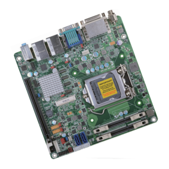
Page 9: Chapter 2 - Hardware Installation
Chapter 2 Chapter 2 - Hardware Installation Important: Board Layout Electrostatic discharge (ESD) can damage your board, processor, disk drives, add-in boards, and other components. Perform installation procedures at an ESD workstation only. If such a station is not available, you can provide some ESD protection by wear- 4-pin power (optional) ing an antistatic wrist strap and attaching it to a metal part of the system chassis. -
Page 10: Installing The Dimm Module
Chapter 2 Installing the DIMM Module The system board supports the following memory interface. Note: Single Channel (SC) The system board used in the following illustrations may not resemble the actual Data will be accessed in chunks of 64 bits (8B) from the memory channels. board. -
Page 11: Cpu
Chapter 2 6. Grasping the module by its edges, position the module above the socket with the “notch” in the module aligned with the “key” on the socket. The keying mechanism ensures the module can be plugged into the socket in only one way. The system board is equipped with a surface mount LGA 1150 socket. -
Page 12: Installing The Cpu
Chapter 2 Load lever Installing the CPU 5. Lifting the load lever will at the same time lift the load plate. 1. Make sure the PC and all other peripheral devices connected to it has been powered down. Lift the load lever up to 2. - Page 13 Chapter 2 8. Close the load plate then 7. Insert the CPU into the push the load lever down. socket. The gold triangular mark on the CPU must While closing the load align with the corner of plate, make sure the front the CPU socket shown on Retention knob edge of the load plate...
-
Page 14: Installing The Fan And Heat Sink
Chapter 2 Installing the Fan and Heat Sink 4. Rotate each push-pin ac- cording to the direction of the arrow shown on top of The CPU must be kept cool by using a CPU fan with heat sink. Without sufficient air circula- the pin. -
Page 15: Jumper Settings
Chapter 2 Jumper Settings Auto Power-on Select Clear CMOS Data 1-2 On: Power-on via Power Button (default) JP11 2-3 On: Power-on via AC power JP11 is used to select the method of powering on the system. If you want the system to power-on whenever AC power comes in, set JP11 pins 2 and 3 to On. -
Page 16: Usb Power Select
Chapter 2 USB Power Select COM 2 RS422/485 Select 1-2 On: +5V USB 3.0 1-2 (default) (JP3) COM 2: RS422/485 USB 2.0 2-3 (JP2) 2-3 On: +5V_standby USB 4-5 USB 8-9/11 (JP9) (JP8) JP6 is used to configure the COM port 2 to RS422 or RS485. The pin functions of the COM port will vary according to the jumper’s setting. -
Page 17: Digital I/O Power Select
Chapter 2 Digital I/O Power Select Digital I/O Output State DIO 0-3 DIO 4-7 (JP10) (JP12) JP13 1-2 On: +5V_standby 2-3 On: +5V 2-3 On: GND 1-2 On: +5V or (default) (default) +5V_standby JP13 is used to select the power of DIO (Digital I/O) signal. Based on the power level of DIO (Digital I/O) selected on JP13, JP10 (DIO pin 0-3) and JP12 (DIO pin 4-7) are used to select the state of DIO output: pull high or pull low. -
Page 18: Mini Pcie/Msata Signal Select
Chapter 2 Mini PCIe/mSATA Signal Select Mini PCIe/mSATA Power Select 1-4-7-10, 2-5-8-11 On: PCIe (default) 1-2 On: +3.3V (default) 2-3 On: +3.3V_standby 2-5-8-11, 3-6-9-12 On: mSATA JP4 is used to select the power supplied with the Mini PCIe. JP5 is used to select the Mini PCIe signal: PCIe (default) or mSATA. Chapter 2 Hardware Installation www.dfi... -
Page 19: Rear Panel I/O Ports
Chapter 2 Rear Panel I/O Ports 12V DC-in (HD171)/19~24V DC-in (HD173) DC-in DVI-I COM 1 LAN 1 LAN 2 (DVI-D signal) Line-in Line-out DC-in Mic-in USB 3.0 USB 2.0 The rear panel I/O ports consist of the following: • 1 12V (HD171) or 19~24V (HD173) DC-in jack or 4-pin power connector* (optional) •... -
Page 20: Com (Serial) Ports
Chapter 2 COM (Serial) Ports Graphics Interfaces The display ports consist of the following: • 1 VGA port • 1 DP port • 1 DVI-D port DVI-D COM 1 COM 1: RS232 1 2 3 4 5 6 7 8 9 COM 2 COM 4 COM 2: RS422/485 COM 3/COM 4: RS232... -
Page 21: Rj45 Lan Ports
Chapter 2 RJ45 LAN Ports USB Ports USB 2 LAN 1 LAN 2 USB 1 LAN 1 USB 3.0 LAN 2 USB 3 USB 2 USB 11 USB 2.0 Data- USB 4-5 USB 8-9 Data+ Features USB 2.0 • Intel I210 PCI Express Gigabit Ethernet controller ®... -
Page 22: Audio
Chapter 2 Audio Wake-On-USB Keyboard/Mouse The Wake-On-USB Keyboard/Mouse function allows you to use a USB keyboard or USB mouse to wake up a system from the S3 (STR - Suspend To RAM) state. To use this function: • Jumper Setting JP2, JP3, JP8 and JP9 must be set to “2-3 On: +5V_standby”. -
Page 23: I/O Connectors
Chapter 2 I/O Connectors SATA (Serial ATA) Power Connectors SATA (Serial ATA) Connectors SATA Power 1 +12V SATA 3.0 6Gb/s Ground Ground SATA 1 SATA Power 0 SATA 0 These SATA power connectors supply power to the SATA drive. Connect one end of the pro- vided power cable to the SATA power connector and the other end to your storage device. -
Page 24: Digital I/O Connector
Chapter 2 Digital I/O Connector Cooling Fan Connectors CPU Fan Speed Control Sense Power Ground System Fan Digital I/O The 8-bit Digital I/O connector provides powering-on function to external devices that are con- nected to these connectors. Digital I/O Connector The fan connectors are used to connect cooling fans. -
Page 25: Chassis Intrusion Connector
Chapter 2 Chassis Intrusion Connector Front Panel Connector 12 11 Chassis Front ATX-SW RESET-SW Intrusion Panel HDD-LED PWR-LED Signal Ground HDD-LED - HDD LED This LED will light when the hard drive is being accessed. RESET-SW - Reset Switch This switch allows you to reboot without having to power off the system. The board supports the chassis intrusion detection function. -
Page 26: Expansion Slots
Chapter 2 Expansion Slots Standby Power LED Mini PCI Express PCI Express x16 Standby Power LED Mini PCI Express Slot This LED will light red when the system is in the standby mode. It indicates that there is pow- er on the system board. Power-off the PC and then unplug the power cord prior to installing The Mini PCIe socket is used to install a Mini PCIe card. -
Page 27: Battery
Chapter 2 Battery +3.3V Battery The lithium ion battery powers the real-time clock and CMOS memory. It is an auxiliary source of power when the main power is shut off. Safety Measures • Danger of explosion if battery incorrectly replaced. •... -
Page 28: Chapter 3 - Bios Setup
Chapter 3 Chapter 3 - BIOS Setup Legends Overview Keys Function The BIOS is a program that takes care of the basic level of communication between the CPU and peripherals. It contains codes for various advanced features found in this system board. Right and Left arrows Moves the highlight left or right to select a menu. -
Page 29: Ami Bios Setup Utility
Chapter 3 AMI BIOS Setup Utility Advanced The Advanced menu allows you to configure your system for basic operation. Some entries are Main defaults required by the system board, while others, if enabled, will improve the performance of your system or let you set some features according to your preference. The Main menu is the first screen that you will see when you enter the BIOS Setup Utility. - Page 30 Chapter 3 ACPI Power Management Configuration Trusted Computing This section is used to configure the ACPI Power Management. This section configures settings relevant to Trusted Computing innovations. Aptio Setup Utility - Copyright (C) 2012 American Megatrends, Inc. Aptio Setup Utility - Copyright (C) 2012 American Megatrends, Inc. Advanced Advanced Confi...
- Page 31 Chapter 3 CPU Configuration SATA Configuration This section is used to configure the CPU. It will also display the detected CPU information. This section is used to configure the settings of SATA device. Aptio Setup Utility - Copyright (C) 2012 American Megatrends, Inc. Aptio Setup Utility - Copyright (C) 2012 American Megatrends, Inc.
- Page 32 Chapter 3 When IDE mode is selected in the SATA Mode Selection, it will display the following SATA Controller Speed information: Indicates the maximum speed that the SATA controller can support. Aptio Setup Utility - Copyright (C) 2012 American Megatrends, Inc. Port 0, Port 1 and mSATA Port Advanced SATA Controller(s)
- Page 33 Chapter 3 PCH-FW Configuration USB Configuration This section is used to configure the parameters of Management Engine Technology. This section is used to configure the parameters of the USB device. Aptio Setup Utility - Copyright (C) 2012 American Megatrends, Inc. Aptio Setup Utility - Copyright (C) 2012 American Megatrends, Inc.
- Page 34 Chapter 3 Super IO Configuration Serial Port 1 Configuration to Serial Port 4 Configuration This section is used to configure the I/O functions supported by the onboard Super I/O chip. Sets the parameters of serial port 1 (COM A) to serial port 4 (COM D). Aptio Setup Utility - Copyright (C) 2012 American Megatrends, Inc.
- Page 35 Chapter 3 PC Health Status This section displays the hardware health monitor. Aptio Setup Utility - Copyright (C) 2012 American Megatrends, Inc. Advanced Aptio Setup Utility - Copyright (C) 2012 American Megatrends, Inc. Serial Port 3 Confi guration Enable or Disable Serial Advanced Port (COM) Serial Port...
- Page 36 Chapter 3 System Smart Fan Control Network Stack When this feature is set to Automatic, the System’s fan speed will rotate according to Aptio Setup Utility - Copyright (C) 2012 American Megatrends, Inc. the System’s temperature. The higher the temperature, the faster the speed of rota- Advanced tion.
-
Page 37: Chipset
Chapter 3 Chipset Ipv4 PXE Support When enabled, Ipv4 PXE boot supports. When disabled, Ipv4 PXE boot option will not This section configures relevant chipset functions. be created. Ipv6 PXE Support Aptio Setup Utility - Copyright (C) 2012 American Megatrends, Inc. Main Advanced Chipset... - Page 38 Chapter 3 Graphics Configuration DVMT Pre-Allocated This field configures the graphics settings. Selects DVMT 5.0 Pre-Allocated (Fixed) Graphics Memory size used by the Internal Graphics Device. Please refer to the screen shown below. Aptio Setup Utility - Copyright (C) 2012 American Megatrends, Inc. Aptio Setup Utility - Copyright (C) 2012 American Megatrends, Inc.
- Page 39 Chapter 3 NB PCIe Configuration LCD Control This field is used to configure the settings of NB PCI Express. This field configures the LCD control. Aptio Setup Utility - Copyright (C) 2012 American Megatrends, Inc. Aptio Setup Utility - Copyright (C) 2012 American Megatrends, Inc. Chipset Chipset NB PCIe Confi...
- Page 40 Chapter 3 Memory Configuration PCH-IO Configuration This field only displays the memory configuration. This section illustrates the PCH parameters. Aptio Setup Utility - Copyright (C) 2012 American Megatrends, Inc. Aptio Setup Utility - Copyright (C) 2012 American Megatrends, Inc. Chipset Chipset Memory Information Intel PCH RC Version...
- Page 41 Chapter 3 PCI Express Configuration USB Configuration This field is used to configure the PCI Express settings. This field is used to configure the USB settings. Aptio Setup Utility - Copyright (C) 2012 American Megatrends, Inc. Aptio Setup Utility - Copyright (C) 2012 American Megatrends, Inc. Chipset Chipset PCI Express Confi...
- Page 42 Chapter 3 XHCI Mode USB Ports Per-Port Disable Control Selects the operation mode of XHCI controller. These options are Auto, Enabled, and This field is used to control each of the USB ports (0~13) disabling. When enabled, Disabled. When Disabled, it will display the following information: it will display the following information: Aptio Setup Utility - Copyright (C) 2012 American Megatrends, Inc.
-
Page 43: Boot
Chapter 3 Boot PCH Azalia Configuration This field is used to configure the PCH Azalia settings. Aptio Setup Utility - Copyright (C) 2012 American Megatrends, Inc. Main Advanced Chipset Boot Security Save & Exit Aptio Setup Utility - Copyright (C) 2012 American Megatrends, Inc. Boot Confi... -
Page 44: Security
Chapter 3 Security CSM Parameters Aptio Setup Utility - Copyright (C) 2012 American Megatrends, Inc. Aptio Setup Utility - Copyright (C) 2012 American Megatrends, Inc. Main Advanced Chipset Boot Security Save & Exit Main Advanced Chipset Boot Security Save & Exit This option controls if Launch CSM [Enabled]... -
Page 45: Save & Exit
Chapter 3 Save & Exit Updating the BIOS To update the BIOS, you will need the new BIOS file and a flash utility, AFUDOS. Aptio Setup Utility - Copyright (C) 2012 American Megatrends, Inc. EXE. Please contact technical support or your sales representative for the files. Main Advanced Chipset... -
Page 46: Notice: Bios Spi Rom
Chapter 3 Notice: BIOS SPI ROM 1. The Intel Management Engine has already been integrated into this system board. Due to ® the safety concerns, the BIOS (SPI ROM) chip cannot be removed from this system board and used on another system board of the same model. 2. -
Page 47: Chapter 4 - Supported Software
Install drivers, utilities and software applications that are required to facilitate and enhance the performance of the system board. You may acquire the software from your sales representa- tives, from an optional DVD included in the shipment, or from the website download page at https://www.dfi.com/DownloadCenter. For Windows 8 Note: This step can be ignored if the applications are standalone files. - Page 48 Chapter 4 For Windows XP Microsoft .NET Framework 3.5 (For Windows XP) Note: Before installing Microsoft .NET Framework 3.5, make sure you have updated your Windows XP operating system to Service Pack 3. To install the driver, click “Microsoft .NET Framework 3.5” on the main menu. 1.
- Page 49 Chapter 4 Intel Chipset Software Installation Utility 3. Click Exit. The Intel Chipset Software Installation Utility is used for updating Windows INF files so that ® the Intel chipset can be recognized and configured properly in the system. To install the utility, click “Intel Chipset Software Installation Utility” on the main menu. 1.
- Page 50 Chapter 4 Microsoft DirectX 9.0C (For Windows XP) 3. Go through the readme document for more installa- tion tips then click Next. To install the utility, click “Microsoft DirectX 9.0C Driver” on the main menu. 1. Click “I accept the agreement”...
- Page 51 Chapter 4 Intel HD Graphics Drivers (For Windows XP) 4. Setup is now installing the driver. Click Next to continue. To install the driver, click “Intel HD Graphics Drivers” on the main menu. 1. To start installation, click Next. 5. Click “Yes, I want to restart this computer now”...
- Page 52 Chapter 4 Intel HD Graphics Drivers (For Windows 7 and Windows 8) 3. Go through the readme document for system re- quirements and installation To install the driver, click “Intel HD Graphics Drivers” on the main menu. tips then click Next. 1.
- Page 53 Chapter 4 Intel Management Engine Drivers 3. Setup is currently installing the driver. After installation has completed, click Next. To install the driver, click “Intel Management Engine Drivers” on the main menu. 1. Setup is ready to install the driver. Click Next. 4.
- Page 54 Chapter 4 Audio Drivers Intel LAN Drivers (For Windows XP) To install the driver, click “Audio Drivers” on the main menu. The LAN drivers for Windows XP supporting on the HD631-Q87 system board has to be installed manually. When you want to install the LAN driver for Windows XP, please follow the steps below to accomplish the installation.
- Page 55 Chapter 4 3. Choose the option "Don't 6. Insert the installation disk search. I will choose the and make sure the selected driver to install" in order to drive is correct. select the device driver from a list, and click "Next." (For 32-bit, the fi...
- Page 56 Chapter 4 Intel LAN Drivers (For Windows 7 and Windows 8) 9. Click "Finish" to close the wizard. To install the driver, click “Intel LAN Drivers” on the main menu. 1. Setup is ready to install the driver. Click Next. 10.
- Page 57 DFI Utility 4. Click Install to begin the installation. DFI Utility provides information about the board, Watchdog,and DIO. To access the utility, click “DFI Utility” on the main menu. Note: If you are using Windows 7, you need to access the operating system as an administrator to be able to install the utility.
- Page 58 Chapter 4 3. Click “Install” to begin the The DFI Utility icon will appear on the desktop. Double-click the icon to open the utility. installation. 4. After completing installa tion, click “Finish”. Information HW Health Chapter 4 Supported Software www.dfi .com...
- Page 59 Chapter 4 HW Health Set WatchDog Chapter 4 Supported Software www.dfi .com...
- Page 60 Chapter 4 Intel USB 3.0 Drivers (For Windows 7) 3. Go through the readme docu- ment for more installation tips then click Next. To install the driver, click “Intel USB 3.0 Driver” on the main menu. 1. Setup is ready to install the driver. Click Next.
- Page 61 Chapter 4 Intel Rapid Storage Technology 3. Read the license agreement then click Yes. (For Windows 7 and Windows 8) The Intel Rapid Storage Technology is a utility that allows you to monitor the current status of the SATA drives. It enables enhanced performance and power management for the storage subsystem.
- Page 62 Chapter 4 Infineon TPM Driver and Tool (optional) 6. Click “Yes, I want to restart my computer now” then click Finish. To install the driver, click “Infineon TPM driver and tool (option)” on the main menu. Restarting the system will allow the new software installation to take 1.
- Page 63 Chapter 4 4. Enter the necessary information 7. TPM requires installing the Micro- and then click Next. soft Visual C++ package prior to installing the utility. Click Install. 5. Select a setup type and then click 8. The setup program is currently Next.
- Page 64 Chapter 4 Adobe Acrobat Reader 9.3 10. Click “Yes“ to restart your system. To install the reader, click “Adobe Acrobat Reader 9.3” on the main menu. 1. Click Next to install or click Change Destination Folder to select another folder. 2.
-
Page 65: Chapter 5 - Digital I/O Programming Guide
Chapter 5 Chapter 5 - Digital I/O Programming Guide The Configuration Register (register 3) configures the direction of the I/O pins. If a bit in this register is set to 1, the corresponding port pin is enabled as an input with a high-impedence Register Description output driver. - Page 66 Chapter 5 Function Description GPIO Output Process I2CWriteByte(SlaveAddr, SubAddr, Data): 0x42 #defi ne SLAVE_ADDR Write a Byte data to a specified I2C Device. 0x00 #defi ne INPUT_PORT 0x01 #defi ne OUTPUT_PORT 0x02 I2CReadByte(SlaveAddr, SubAddr, *Data): #defi ne INVERSION_PORT 0x03 Read a Byte data from a specified I2C Device. #defi...
-
Page 67: Appendix A - Watchdog Sample Code
Appendix A Appendix A - Watchdog Sample Code ;Software programming example: ;--------------------------------------------- ;(1) Enter Super IO Confi guration mode ;--------------------------------------------- DX,4EH AL,87H DX,AL DX,AL ;------------------------------------------------------------------------------------------- ;(2) Confi guration Logical Device 8, register CRF0/CRF1 (WDT Control/WDT timer) ;------------------------------------------------------------------------------------------- DX,4EH AL,07H ;Ready to Program Logical Device DX,AL DX,4FH AL,08H... -
Page 68: Appendix B - System Error Message
Appendix B Appendix B - System Error Message Hard Disk(s) fail (20) When the BIOS encounters an error that requires the user to correct something, either a beep HDD initialization error. code will sound or a message will be displayed in a box in the middle of the screen and the message, PRESS F1 TO CONTINUE, CTRL-ALT-ESC or DEL TO ENTER SETUP, will be shown in Hard Disk(s) fail (10) the information box at the bottom. -
Page 69: Appendix C - Troubleshooting
Appendix C Appendix C - Troubleshooting Checklist The picture seems to be constantly moving. Troubleshooting Checklist 1. The monitor has lost its vertical sync. Adjust the monitor’s vertical sync. 2. Move away any objects, such as another monitor or fan, that may be creating a magnetic This chapter of the manual is designed to help you with problems that you may encounter field around the display. - Page 70 Appendix C Hard Drive System Board 1. Make sure the add-in card is seated securely in the expansion slot. If the add-in card is Hard disk failure. loose, power off the system, re-install the card and power up the system. 1.
Need help?
Do you have a question about the HD171/HD173-H81 and is the answer not in the manual?
Questions and answers