
Related Manuals for Grantech SYM76999VGGA


Summary of Contents for Grantech SYM76999VGGA
- Page 1 INTEL 3rd Generation Core i Series Processor ATX Industrial Motherboard SYM76999VGGA User’s Manual GRANTECH CO., LTD.
-
Page 2: Copyright Notice
▍ Preface Copyright Notice The material in this document is our intellectual property. We take every care in the preparation of this document, but no guarantee is given as to the correctness of its contents. Our products are under continual improvement and we reserve the right to make changes without notice. -
Page 3: Safety Instructions
Safety Instructions ■ Always read the safety instructions carefully. ■ Keep this User’s Manual for future reference. ■ Keep this equipment away from humidity. ■ Lay this equipment on a reliable flat surface before setting it up. ■ The openings on the enclosure are for air convection hence protects the equipment from overheating. -
Page 4: Ce Conformity
▍ Preface CE Conformity Hereby, we declare that this device is in compliance with the essential safety requirements and other relevant provisions set out in the European Directive. FCC-B Radio Frequency Interference Statement This equipment has been tested and found to comply with the limits for a Class B digital device, pursuant to Part 15 of the FCC Rules. -
Page 5: Weee Statement
WEEE Statement ENGLISH Under the European Union (“EU”) Directive on Waste Electrical and Electronic Equipment, Directive 2002/96/EC, which takes effect on August 13, 2005, products of “electrical and electronic equipment” cannot be discarded as mu- nicipal waste anymore and manufacturers of covered electronic equipment will be obligated to take back such products at the end of their useful life. - Page 6 ▍ Preface SRPSKI Po Direktivi Evropske unije (“EU”) o odbačenoj ekektronskoj i električnoj opremi, Di- rektiva 2002/96/EC, koja stupa na snagu od 13. Avgusta 2005, proizvodi koji spadaju pod “elektronsku i električnu opremu” ne mogu više biti odbačeni kao običan otpad i proizvođači ove opreme biće prinuđeni da uzmu natrag ove proizvode na kraju njihovog uobičajenog veka trajanja.
-
Page 7: Table Of Contents
Contents Copyright Notice ................. ii Trademarks ..................ii Revision History .................. ii Safety Instructions ................iii CE Conformity ..................iv FCC-B Radio Frequency Interference Statement ......iv WEEE Statement ................v Chapter 1 Overview ������������������������������������������������������������������������������� 1-1 Mainboard Specifications ..............1-2 Mainboard Layout ................1-4 Chapter 2 Hardware Setup��������������������������������������������������������������������... -
Page 8: Chapter 1 Overview
Chapter 1 Overview Thank you for choosing SYM76999VGGA, an excellent industrial computer board. Based on the innovative Intel Panther Point chipset ® for optimal system efficiency, SYM76999VGGA supports Ivy Bridge and Sandy Bridge processor series in socket LGA1155 and supports up to four DDR3 1066/1333/1600 UDIMM slots to provide the maximum of 32GB memory capacity. -
Page 9: Mainboard Specifications
▍ Overview Mainboard Specifications ■ Intel Ivy Bridge series and Sandy Bridge series processor in socket LGA1155 (Optional) Chipset ■ Intel Q77 PCH ■ Support iAMT 8.0 ■ Memory 4 DDR3 1066/1333/1600 UDIMM slots ■ Supports the maximum of 32GB ■... - Page 10 Onboard ■ 3 USB 2.0 pin-headers ■ 5 Serial port connectors Connectors/ ■ 1 GPIO pin-header Pinheaders ■ 1 Front Audio pin-header ■ 1 Chassis Intrusion pin-header ■ 1 Parallel Port pin-header ■ 1 TPM Module connector (optional) ■ 1 Front Panel pin-header Slot ■...
-
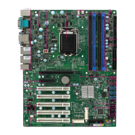
Page 11: Mainboard Layout
Mainboard Layout Fan Power 4-pin Power DIMM Slot Connector Power Jumper Power Jumper Connector Serial Port Connector COM Power Jumper COM Power Jumper 24-pin Power Connector Fan Power Connector Clear CMOS Jumper PCI-E Slot SATA Connector Slot Front Audio GPIO Header Pin-header mSATA Slot... -
Page 12: Chapter 2 Hardware Setup
Chapter 2 Hardware Setup This chapter provides you with the information on mainboard hardware configurations. Incorrect setting of jumpers and connectors may damage your mainboard. Please pay special attention not to connect these headers in wrong direction. DO NOT adjust any jumper while the mainboard is powered... -
Page 13: Components Reference Guide
▍ Hardware Setup Components Reference Guide Port Name Port Type Page LGA 1155 CPU Socket DIMM1~4 DDR3 Memory Slots JPWR1~2 ATX Power Connectors Back Panel I/O Ports Chassis Intrusion Connector 2-12 SATA1~5 SATA Connectors 2-12 JTPM1 TPM Module Connector 2-13 CPUFAN,SYSFAN1~3 Fan Power Connectors 2-13... -
Page 14: Cpu
CPU (Central Processing Unit) When you are installing the CPU, make sure that you install the cooler to prevent overheating. If you do not have the CPU cooler, consult your dealer before turning on the computer. Important Overheating Overheating will seriously damage the CPU and system. Always make sure the cooling fan can work properly to protect the CPU from overheating. - Page 15 ▍ Hardware Setup CPU & Cooler Installation When you are installing the CPU, make sure the CPU has a cooler at- tached on the top to prevent overheating. Meanwhile, do not forget to apply some thermal paste on CPU before installing the heat sink/cooler fan for better heat dispersion.
- Page 16 Secure the lever near the Make sure the four hooks are hook end under the reten- in proper position before you tion tab. install the cooler. Align the holes on the mainboard with the cooler. Push down the cooler until its four clips get wedged into the holes of the mainboard.
-
Page 17: Memory
▍ Hardware Setup Memory These DIMM slots are intended for memory modules. DDR3 240-pin, 1�5V 48x2=96 pin 72x2=144 pin Dual-Channel mode Population Rule In Dual-Channel mode, the memory modules can transmit and receive data with two data bus lines simultaneously. Enabling Dual-Channel mode can enhance the system performance. - Page 18 Installing Memory Modules The memory module has only one notch on the center and will only fit in the right orientation. Insert the memory module vertically into the DIMM slot. Then push it in until the golden finger on the memory module is deeply inserted in the DIMM slot.
-
Page 19: Power Supply
▍ Hardware Setup Power Supply 24-Pin Power Connector: JPWR1 This connector allows you to connect an 24-pin power supply. To connect the 24-pin power supply, make sure the plug of the power supply is inserted in the proper orientation and the pins are aligned. Then push down the power supply firmly into the connector. -
Page 20: Back Panel I/O
Back Panel I/O Mouse/ Keyboard LAN Jack LAN Jack Port Serial Port Line-In Jack VGA Port Line-Out Jack Mic-In Jack Displayport USB 2�0 DVI-D Port USB 3�0 USB 3�0 Port Port Port ▶ Mouse/Keyboard Port The standard PS/2 mouse/keyboard DIN connector is for a PS/2 mouse/ keyboard. - Page 21 ▍ Hardware Setup ▶ RS-232/422/485 Serial Port Connector The serial port is a 16550A high speed communications port that sends/ receives 16 bytes FIFOs. You can attach a serial mouse or other serial devices directly to the connector. RS-232 SIGNAL DESCRIPTION Data Carrier Detect Receive Data...
- Page 22 ▶ The standard RJ-45 LAN jack is for connection to the Local Area Network (LAN). You can connect a network cable to it. Left LED Right LED Left LED Right LED (Active LED) (100M/1000M Speed LED) LED Color Orange Green/Yellow No Transmission Orange (Lighting) 10M Cable...
-
Page 23: Connector
▍ Hardware Setup Connector Chassis Intrusion Pinheader: CI1 This connector is provided to connect the chassis intrusion switch cable. If the chassis is opened, the chassis intrusion mechanism will be activated. The system will record this status and show a warning message on the screen. - Page 24 TPM Module Connector: JTPM1 This connector connects to a TPM (Trusted Platform Module). Please refer to the TPM security platform manual for more details and usages. Fan Power Connector: CPUFAN1, SYSFAN1, SYSFAN2, SYSFAN3 The fan power connector supports system cooling fan with +12V. When connecting the wire to the connectors, always note that the red wire is the positive and should be connected to the +12V;...
- Page 25 ▍ Hardware Setup GPIO Pin-header: JGPIO1 This connector is provided for the General-Purpose Input/Output (GPIO) peripheral module. Front Panel Pin-header: JFP1 This front panel connector is provided for electrical connection to the front panel switches & LEDs and is compliant with Intel Front Panel I/O Con- nectivity Design Guide.
- Page 26 Front USB Pin-header: JUSB1 ~ JUSB3 This connector, compliant with Intel I/O Connectivity Design Guide, is ideal for connecting high-speed USB interface peripherals such as USB HDD, digital cameras, MP3 players, printers, modems and the like. USB 2�0 Bracket (Optional) Important Note that the pins of +5V and GND must be connected correctly to avoid possible damage.
- Page 27 ▍ Hardware Setup Serial Port Connector: COM2 ~ COM6 This connector is a 16550A high speed communications port that sends/ receives 16 bytes FIFOs. You can attach a serial device to it through an optional serial port bracket. RS-232 SIGNAL DESCRIPTION Data Carrier Detect Receive Data...
- Page 28 Front Audio Pin-header: JAUD1 This connector allows you to connect the front panel audio and is compliant with Intel Front Panel I/O Connectivity Design Guide. Parallel Port Header: JLPT1 The mainboard provides a 26-pin header for connection to an optional paral- lel port bracket.
-
Page 29: Jumper
▍ Hardware Setup Jumper Clear CMOS Jumper: CLR_CMOS1 There is a CMOS RAM onboard that has a power supply from an external battery to keep the data of system configuration. With the CMOS RAM, the system can automatically boot OS every time it is turned on. If you want to clear the system configuration, set the jumper to clear data. - Page 30 AT/ATX Select Jumper: JAT1 This jumper allows users to select between AT and ATX power. JAT1 AT Power ATX Power Back Panel COM Port Power Jumper: JCOMP1 This jumper specifies the operation voltage of the serial ports on the back panel.
-
Page 31: Slot
▍ Hardware Setup Slot PCI-E (Peripheral Component Interconnect Express) Slot The PCIE slot supports the PCIE interface expansion card. PCI (Peripheral Component Interconnect) Slot The PCI slot supports LAN card, SCSI card, USB card, and other add-on cards that comply with PCI specifications. 32-bit PCI Slot Important When adding or removing expansion cards, make sure that you unplug the... - Page 32 Mini PCI-E Slot The Mini PCI-E slot is provided for wireless LAN card, TV tuner card, and Robson NAND Flash card . mSATA Slot The mSATA slot is provided for mSATA SSD device . 2-21...
Need help?
Do you have a question about the SYM76999VGGA and is the answer not in the manual?
Questions and answers