Table of Contents
Advertisement
Quick Links
This user's guide describes the characteristics, operation, and use of the ADS8900B evaluation module
(EVM) performance demonstration kit (PDK). This kit is an evaluation platform for the ADS8900B, which is
a 20-bit, 1-MSPS, fully-differential input, successive approximation register (SAR) analog-to-digital
converter (ADC) that features an enhanced serial multiSPI™ digital interface. The EVM-PDK eases the
evaluation of the ADS8900B device with hardware, software, and computer connectivity through the
universal serial bus (USB) interface. This user's guide includes complete circuit descriptions, schematic
diagrams, and a bill of materials.
The following related documents are available through the Texas Instruments web site at www.ti.com.
multiSPI is a trademark of Texas Instruments.
multiSPI is a registered trademark of Texas Instruments.
Microsoft, Windows are registered trademarks of Microsoft Corporation.
LabVIEW is a trademark of National Instruments.
All other trademarks are the property of their respective owners.
SBAU269 – October 2016
Submit Documentation Feedback
Related Documentation
Device
ADS8900B
OPA625
OPA376
OPA378
REF5050
TPS7A4700
Copyright © 2016, Texas Instruments Incorporated
ADS8900BEVM-PDK
Literature Number
SBAS728
SBOS688
SBOS406
SBOS417
SBOS410
SBVS204
User's Guide
SBAU269 – October 2016
1
ADS8900BEVM-PDK
Advertisement
Table of Contents

Related Manuals for Texas Instruments ADS8900BEVM-PDK


Summary of Contents for Texas Instruments ADS8900BEVM-PDK
- Page 1 ADS8900B device with hardware, software, and computer connectivity through the universal serial bus (USB) interface. This user's guide includes complete circuit descriptions, schematic diagrams, and a bill of materials. The following related documents are available through the Texas Instruments web site at www.ti.com. Related Documentation Device...
-
Page 2: Table Of Contents
Schematic Diagram (Page 1) of the ADS8900BEVM PCB ............Schematic Diagram (Page 2) of the ADS8900BEVM PCB ............Schematic Diagram (Page 3) of the ADS8900BEVM PCB List of Tables ADS8900BEVM-PDK SBAU269 – October 2016 Submit Documentation Feedback Copyright © 2016, Texas Instruments Incorporated... - Page 3 J1 and J2 Configuration per Input Common-Mode ............ External Source Requirements for Evaluation of the ADS8900B ............External Source Requirements for ADS8900B Evaluation ..................ADS8900BEVM Bill of Materials SBAU269 – October 2016 ADS8900BEVM-PDK Submit Documentation Feedback Copyright © 2016, Texas Instruments Incorporated...
-
Page 4: Overview
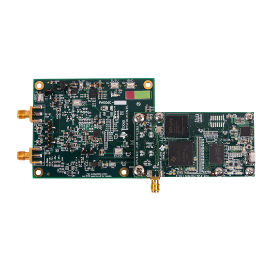
Overview The ADS8900BEVM-PDK is a platform for evaluating the performance of the ADS8900B SAR ADC, which is a fully-differential input, 20-bit, 1-MSPS device. The evaluation kit includes the ADS8900BEVM board and the precision host interface (PHI) controller board that enables the accompanying computer software to communicate with the ADC over USB for data capture and analysis. -
Page 5: Analog Interface
ADC inputs dynamically low impedance. Thus, the evaluation board has low impedance on board drivers that maintain ADC performance with maximum loading at the full device throughput of 1-MSPS for signal. SBAU269 – October 2016 ADS8900BEVM-PDK Submit Documentation Feedback Copyright © 2016, Texas Instruments Incorporated... -
Page 6: Opa625 Differential Input Driving Path
) between 0 Ω and 32 Ω, with 0-V common mode. R1 must be changed to compensate for larger external source impedance (R ) values or for 2.5-V external source common-mode, as explained in Section 2.2.3. ADS8900BEVM-PDK SBAU269 – October 2016 Submit Documentation Feedback Copyright © 2016, Texas Instruments Incorporated... -
Page 7: Common-Mode Selection Jumpers
+ R s•À + R Equation 1 Equation 2 the value of R1 must be calculated to satisfy Equation 2.5 V Q ADC_V Q 2.6 V SBAU269 – October 2016 ADS8900BEVM-PDK Submit Documentation Feedback Copyright © 2016, Texas Instruments Incorporated... -
Page 8: Onboard Adc Reference
USB. There are two devices on the EVM with which the PHI communicates: the ADS8900B ADC (over SPI or multiSPI) and the EEPROM (over I C). The EEPROM comes pre-programmed with the information required to configure and initialize the ADS8900BEVM-PDK platform. Once the hardware is initialized, the EEPROM is no longer used. multiSPI for ADC Digital IO ®... -
Page 9: Power Supplies
ADS8900BEVM-PDK Initial Setup This section explains the initial hardware and software setup procedure that must be completed for the proper operation of the ADS8900BEVM-PDK. Default Jumper Settings Jumper settings are determined by common mode and source impedance of the external source that provides a differential signal to the board. -
Page 10: Ads8900B Software Installation Prompts
As a part of the ADS8900BEVM GUI installation, a prompt with a Device Driver Installation will appear on the screen. Click Next to proceed. Figure 4. Device Driver Installation Wizard Prompts ADS8900BEVM-PDK SBAU269 – October 2016 Submit Documentation Feedback Copyright © 2016, Texas Instruments Incorporated... -
Page 11: Labview Run-Time Engine Installation
NOTE: A notice may appear on the screen stating that Widows cannot verify the publisher of this driver software. Select Install this driver software anyway. The ADS8900BEVM-PDK requires LabVIEW™ Run-Time Engine and may prompt for the installation of this software, if not already installed. -
Page 12: Ads8900Bevm Folder Post-Installation
ADS8900BEVM-PDK Initial Setup www.ti.com After these installations, verify that C:\Program Files (x86)\Texas Instruments\ADS8900BEVM is as shown Figure Figure 6. ADS8900BEVM Folder Post-Installation ADS8900BEVM-PDK SBAU269 – October 2016 Submit Documentation Feedback Copyright © 2016, Texas Instruments Incorporated... -
Page 13: Ads8900Bevm-Pdk Operation
ADS8900BEVM-PDK Operation www.ti.com ADS8900BEVM-PDK Operation The following instructions are a step-by-step guide to connecting the ADS8900BEVM-PDK to the computer and evaluating the performance of the ADS8900B: 1. Connect the ADS8900BEVM to the PHI. Install the two screws as indicated in Figure 2. -
Page 14: Launch The Evm Gui Software
ADS8900BEVM-PDK Operation www.ti.com 3. Launch the ADS8900BEVM GUI software, as shown in Figure Figure 8. Launch the EVM GUI Software ADS8900BEVM-PDK SBAU269 – October 2016 Submit Documentation Feedback Copyright © 2016, Texas Instruments Incorporated... -
Page 15: Evm Gui Global Settings For Adc Control
ADS8900B datasheet (TBD). The selected data capture protocol is summarized in the Protocol Selected indicator box. SBAU269 – October 2016 ADS8900BEVM-PDK Submit Documentation Feedback Copyright © 2016, Texas Instruments Incorporated... - Page 16 ADC RESETs to the RESET configuration explained in the datasheet (TBD). The GUI also updates the Interface Configuration settings and the Register Map to reflect the device RESET state. ADS8900BEVM-PDK SBAU269 – October 2016 Submit Documentation Feedback Copyright © 2016, Texas Instruments Incorporated...
-
Page 17: Register Map Configuration Tool
The effect of changes in the register value reflect on the ADS8900B device on ADS8900BEVM-PDK based on the Update Mode selection, as described in Section 6.1. -
Page 18: Time Domain Display Tool
Switching pages to any of the Analysis tools described in the subsequent sections, triggers calculations to be performed on the same set of data. Figure 11. Time Domain Display Tool Options ADS8900BEVM-PDK SBAU269 – October 2016 Submit Documentation Feedback Copyright © 2016, Texas Instruments Incorporated... -
Page 19: Spectral Analysis Tool
–140 dBc to analyze noise-free harmonics and spurs in the order of –120 dBc. Such analysis requires at least 262144 samples. SBAU269 – October 2016 ADS8900BEVM-PDK Submit Documentation Feedback Copyright © 2016, Texas Instruments Incorporated... -
Page 20: Spectral Analysis Tool
24-bit ADC. Note that the None option corresponds to not using a window (or using a rectangular window) and is not recommended. ADS8900BEVM-PDK SBAU269 – October 2016 Submit Documentation Feedback Copyright © 2016, Texas Instruments Incorporated... -
Page 21: Histogram Tool
The histogram corresponding to a dc input is displayed on clicking on the Capture button, as shown in Figure Figure 13. Histogram Analysis Tool SBAU269 – October 2016 ADS8900BEVM-PDK Submit Documentation Feedback Copyright © 2016, Texas Instruments Incorporated... -
Page 22: Linearity Analysis Tool
1024. NOTE: This analysis can take a couple of minutes to run and the evaluation board must remain undisturbed during the complete duration of the analysis. ADS8900BEVM-PDK SBAU269 – October 2016 Submit Documentation Feedback Copyright © 2016, Texas Instruments Incorporated... -
Page 23: Reference Settling Analysis
The tool captures the defined number of burst captures and performs the vertical averaging on the burst mode data. The difference between maximum and minimum codes from the averaged data defines the Reference Settling error. SBAU269 – October 2016 ADS8900BEVM-PDK Submit Documentation Feedback Copyright © 2016, Texas Instruments Incorporated... -
Page 24: Reference Settling Tool
ADS8900BEVM-PDK Operation www.ti.com Figure 15. Reference Settling Tool ADS8900BEVM-PDK SBAU269 – October 2016 Submit Documentation Feedback Copyright © 2016, Texas Instruments Incorporated... -
Page 25: Bill Of Materials, Pcb Layout, And Schematics
Thermal Transfer Printable Labels, 0.650" W x 0.200" H - 10,000 per roll RG2012P-2803-B-T5 Susumu Co Ltd RES, 280 k, 0.1%, 0.125 W, 0805 ERJ-3RSFR10V Panasonic RES, 0.1, 1%, 0.1 W, 0603 SBAU269 – October 2016 ADS8900BEVM-PDK Submit Documentation Feedback Copyright © 2016, Texas Instruments Incorporated... - Page 26 CAP, CERM, 10uF, 10V, +/-10%, X7R, 0805 GRM155R71C104KA88D Murata CAP, CERM, 0.1 µF, 16 V, +/- 10%, X7R, 0402 GRM32ER71A476KE15L Murata CAP, CERM, 47 µF, 10 V, +/- 10%, X7R, 1210 ADS8900BEVM-PDK SBAU269 – October 2016 Submit Documentation Feedback Copyright © 2016, Texas Instruments Incorporated...
- Page 27 High-Bandwidth, High-Precision, Low THD+N, 16-Bit and 18-Bit Analog-to-Digital Converter (ADC) OPA625IDBVR Texas Instruments Drivers, DBV0006A REF6025AIDGK Texas Instruments High-Precision Voltage Reference with Integrated High-Bandwidth Buffer, DGK0008A SBAU269 – October 2016 ADS8900BEVM-PDK Submit Documentation Feedback Copyright © 2016, Texas Instruments Incorporated...
-
Page 28: Pcb Layout
Bill of Materials, PCB Layout, and Schematics www.ti.com PCB Layout Figure 16 through Figure 19 illustrate the EVM PCB layout. Figure 16. ADS8900BEVM PCB Layer 1: Top Layer ADS8900BEVM-PDK SBAU269 – October 2016 Submit Documentation Feedback Copyright © 2016, Texas Instruments Incorporated... -
Page 29: Ads8900Bevm Pcb Layer 2: Gnd Plane
Bill of Materials, PCB Layout, and Schematics www.ti.com Figure 17. ADS8900BEVM PCB Layer 2: GND Plane SBAU269 – October 2016 ADS8900BEVM-PDK Submit Documentation Feedback Copyright © 2016, Texas Instruments Incorporated... -
Page 30: Ads8900Bevm Pcb Layer 3: Power Planes
Bill of Materials, PCB Layout, and Schematics www.ti.com Figure 18. ADS8900BEVM PCB Layer 3: Power Planes ADS8900BEVM-PDK SBAU269 – October 2016 Submit Documentation Feedback Copyright © 2016, Texas Instruments Incorporated... -
Page 31: Schematics
Bill of Materials, PCB Layout, and Schematics www.ti.com Figure 19. ADS8900BEVM PCB Layer 4: Bottom Layer Schematics Figure 20 through Figure 22 illustrate the EVM schematics. SBAU269 – October 2016 ADS8900BEVM-PDK Submit Documentation Feedback Copyright © 2016, Texas Instruments Incorporated... -
Page 32: Schematic Diagram (Page 1) Of The Ads8900Bevm Pcb
Version control disabled Assembly Variant: Sheet: warrant that this design will meet the specifications, will be suitable for your application or fit for any particular purpose, or will operate in an implementation. Texas Instruments and/or its Drawn By: Rafael Ordonez File: PA006C_Schematic1.SchDoc... -
Page 33: Schematic Diagram (Page 2) Of The Ads8900Bevm Pcb
Version control disabled Assembly Variant: Sheet: warrant that this design will meet the specifications, will be suitable for your application or fit for any particular purpose, or will operate in an implementation. Texas Instruments and/or its Drawn By: Rafael Ordonez File: PA006C_Schematic2.SchDoc... -
Page 34: Schematic Diagram (Page 3) Of The Ads8900Bevm Pcb
Version control disabled Assembly Variant: Sheet: warrant that this design will meet the specifications, will be suitable for your application or fit for any particular purpose, or will operate in an implementation. Texas Instruments and/or its Drawn By: Rafael Ordonez File: PA006C_Hardware.SchDoc... - Page 35 STANDARD TERMS AND CONDITIONS FOR EVALUATION MODULES Delivery: TI delivers TI evaluation boards, kits, or modules, including demonstration software, components, and/or documentation which may be provided together or separately (collectively, an “EVM” or “EVMs”) to the User (“User”) in accordance with the terms and conditions set forth herein.
- Page 36 FCC Interference Statement for Class B EVM devices NOTE: This equipment has been tested and found to comply with the limits for a Class B digital device, pursuant to part 15 of the FCC Rules. These limits are designed to provide reasonable protection against harmful interference in a residential installation.
- Page 37 【無線電波を送信する製品の開発キットをお使いになる際の注意事項】 開発キットの中には技術基準適合証明を受けて いないものがあります。 技術適合証明を受けていないもののご使用に際しては、電波法遵守のため、以下のいずれかの 措置を取っていただく必要がありますのでご注意ください。 1. 電波法施行規則第6条第1項第1号に基づく平成18年3月28日総務省告示第173号で定められた電波暗室等の試験設備でご使用 いただく。 2. 実験局の免許を取得後ご使用いただく。 3. 技術基準適合証明を取得後ご使用いただく。 なお、本製品は、上記の「ご使用にあたっての注意」を譲渡先、移転先に通知しない限り、譲渡、移転できないものとします。 上記を遵守頂けない場合は、電波法の罰則が適用される可能性があることをご留意ください。 日本テキサス・イ ンスツルメンツ株式会社 東京都新宿区西新宿6丁目24番1号 西新宿三井ビル 3.3.3 Notice for EVMs for Power Line Communication: Please see http://www.tij.co.jp/lsds/ti_ja/general/eStore/notice_02.page 電力線搬送波通信についての開発キットをお使いになる際の注意事項については、次のところをご覧ください。http:/ /www.tij.co.jp/lsds/ti_ja/general/eStore/notice_02.page SPACER EVM Use Restrictions and Warnings: 4.1 EVMS ARE NOT FOR USE IN FUNCTIONAL SAFETY AND/OR SAFETY CRITICAL EVALUATIONS, INCLUDING BUT NOT LIMITED TO EVALUATIONS OF LIFE SUPPORT APPLICATIONS.
- Page 38 Notwithstanding the foregoing, any judgment may be enforced in any United States or foreign court, and TI may seek injunctive relief in any United States or foreign court. Mailing Address: Texas Instruments, Post Office Box 655303, Dallas, Texas 75265 Copyright © 2016, Texas Instruments Incorporated...
- Page 39 IMPORTANT NOTICE Texas Instruments Incorporated and its subsidiaries (TI) reserve the right to make corrections, enhancements, improvements and other changes to its semiconductor products and services per JESD46, latest issue, and to discontinue any product or service per JESD48, latest issue.
Need help?
Do you have a question about the ADS8900BEVM-PDK and is the answer not in the manual?
Questions and answers