GW Instek PSW 30-72 Programming Manual
Multi-range dc power supply
Hide thumbs
Also See for PSW 30-72:
- User manual (187 pages) ,
- Programming manual (87 pages) ,
- User manual (184 pages)

Subscribe to Our Youtube Channel
Related Manuals for GW Instek PSW 30-72


Summary of Contents for GW Instek PSW 30-72
- Page 1 Multi-Range DC Power Supply PSW Series PROGRAMMING MANUAL VERSION: 1.4 ISO-9001 CERTIFIED MANUFACTURER...
- Page 2 This manual contains proprietary information, which is protected by copyright. All rights are reserved. No part of this manual may be photocopied, reproduced or translated to another language without prior written consent of Good Will company. The information in this manual was correct at the time of printing. However, Good Will continues to improve products and reserves the rights to change specification, equipment, and maintenance procedures at any time without notice.
-
Page 3: Table Of Contents
Table of Contents Table of Contents SAFETY INSTRUCTIONS ........... 4 GETTING STARTED ............8 PSW Series Overview ......9 Appearance .......... 14 Configuration Settings ......21 REMOTE CONTROL ............29 Interface Configuration ......30 Socket Server Examples ....... 45 Command Syntax ......... 49 Command List ........ -
Page 4: Safety Instructions
PSW Series Programming Manual AFETY INSTRUCTIONS This chapter contains important safety instructions that you must follow during operation and storage. Read the following before any operation to insure your safety and to keep the instrument in the best possible condition. Safety Symbols These safety symbols may appear in this manual or on the instrument. - Page 5 SAFETY INSTRUCTIONS Do not dispose electronic equipment as unsorted municipal waste. Please use a separate collection facility or contact the supplier from which this instrument was purchased. Safety Guidelines Do not place any heavy object on the PSW. General Guideline Avoid severe impact or rough handling that ...
- Page 6 PSW Series Programming Manual Disconnect the power cord before cleaning. Cleaning the PSW Use a soft cloth dampened in a solution of mild detergent and water. Do not spray any liquid. Do not use chemicals containing harsh material ...
- Page 7 SAFETY INSTRUCTIONS Power cord for the United Kingdom When using the power supply in the United Kingdom, make sure the power cord meets the following safety instructions. NOTE: This lead/appliance must only be wired by competent persons WARNING: THIS APPLIANCE MUST BE EARTHED IMPORTANT: The wires in this lead are coloured in accordance with the following code: Green/ Yellow:...
-
Page 8: Getting Started
PSW Series Programming Manual ETTING STARTED This chapter describes the power supply in a nutshell, including its main features and front / rear panel introduction, as well as an overview of the configuration settings. PSW Series Overview ............9 Series lineup ................9 Main Features ................. -
Page 9: Psw Series Overview
0~160V 0~7.2A 360W PSW 250-4.5 Type I 0~250V 0~4.5A 360W PSW 800-1.44 Type I 0~800V 0~1.44A 360W PSW 30-72 Type II 0~30V 0~72A 720W PSW 80-27 Type II 0~80V 0~27A 720W PSW 160-14.4 Type II 0~160V 0~14.4A 720W PSW 250-9... -
Page 10: Main Features
1080 Watt models Type I Type II Type III Voltage Multi-Range DC Power Supply Voltage Voltage Multi-Range DC Power Supply Multi-Range DC Power Supply PSW 30-36 360W PSW 30-72 720W PSW 30-108 1080W Current Current Current Function OVP/OCP Function OVP/OCP Function... -
Page 11: Accessories
GETTING STARTED Ethernet port Interface Analog connector for analog voltage and current monitoring USB host and device port Accessories Please check the contents before using the PSW. PSW 30/80/160 Accessories Standard Part number Description Accessories CD-ROM User manual, programming manual 4323-30600101 Power cord (Type I/II) - Page 12 PSW Series Programming Manual PSW-002 Simple IDC Tool PSW-003 Contact Removal Tool PSW-005 Series operation cable for 2 units. PSW-006 Parallel operation cable for 2 units. PSW-007 Parallel operation cable for 3 units. GRA-410-J Rack mount adapter (JIS) GRA-410-E Rack mount adapter (EIA) GUG-001 GPIB to USB adapter GTL-240...
- Page 13 GETTING STARTED PSW-008 Basic Accessory Kit: (Air filter x1, Analog control protection dummy x1, Analog control lock level x1 Optional Part number Description Accessories GET-002 Extended terminal PSW-001 Accessory Kit: Pin contact x10, Socket x1, Protection cover x1 PSW-002 Simple IDC Tool PSW-003 Contact...
-
Page 14: Appearance
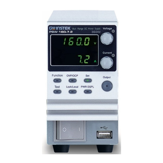
PSW Series Programming Manual Appearance PSW Front Panel 720W: PSW 30-72, 80-27, 160-14.4, 250-9, 800-2.88 Voltage Voltage Multi-Range DC Power Supply PSW 30-72 720W Display knob Current Current knob Cover panel Function OVP/OCP Output Output Test Lock/Local PWR DSPL Power... - Page 15 GETTING STARTED The Function keys along with the Output key will Function Keys light up when a key is active. The Function key is used to Function configure the power supply. Set the over current or over OVP/OCP voltage protection levels. Sets the current and voltage limits.
- Page 16 PSW Series Programming Manual Power bar Indicates the current power output as a percentage. Sets the voltage. Voltage Knob Voltage Sets the current. Current Knob Current Press to turn on the output. The Output Output Output key will light up when the output is active.
-
Page 17: Rear Panel
GETTING STARTED Rear Panel 720W: PSW 30-72, 80-27, 160-14.4 Sense+ USB B Output Analog control terminal port terminal connector Chassis ground Sense- SER.NO. LABEL terminal Output terminal (-) 240V 47 63Hz 1000VA MAX. AC Input 1080W: PSW 30-108, 80-40.5, 160-21.6 360W: PSW 30-36, 80-13.5, 160-7.2... - Page 18 PSW Series Programming Manual 720W: PSW 250-9, 800-2.88 Sense+ USB B Output Analog control terminal port terminals +V connector Sense- terminal SN.C. S SER.NO. LABEL Chassis ground Output terminals -V 240V 47 63Hz 1000VA MAX. AC Input 1080W: PSW 250-13.5, 800-4.32 360W: PSW 250-4.5, 800-1.44 AC Input...
- Page 19 GETTING STARTED Standard 26 pin MIL connector Analog Control (OMRON XG4 IDC plug). Connector The analog control connector is used to monitor current and voltage output, machine status (OVP, OCP, OTP etc.), and for analog control of the current and voltage output. Use an OMRON XG5 IDC socket as the mating socket.
- Page 20 Ethernet Port control and digital monitoring from a PC. Type I: PSW 30-36/80-13.5/ Line Voltage Input 160-7.2/250-4.5, 800-1.44 (Type I/TypeII) Type II: PSW 30-72/80-27/ 160-14.4/250-9, 800-2.88 Voltage Input: 100~240 VAC Line frequency: 50Hz/60 Hz (Automatically switchable) Type III:...
-
Page 21: Configuration Settings
GETTING STARTED Configuration Settings Configuration of the PSW power supplies is divided into five different configuration settings: Normal Function, USB/GPIB, LAN, Power ON Configuration, Calibration Settings and System Settings. Power ON Configuration differs from the other settings in that the settings used with Power ON Configuration settings can only be set during power up. - Page 22 PSW Series Programming Manual 3. Rotate the voltage knob to change Voltage the F setting. F-00~ F-61, F-88~F-89 Range 4. Use the current knob to set the Current parameter for the chosen F setting. 5. Press the Voltage knob to save the Voltage configuration setting.
- Page 23 GETTING STARTED 6. Hold the Function key whilst Steps Voltage Multi-Range DC Power Supply PSW 30-36 360W turning the power on. Current Function OVP/OCP Output 7. The display will show F-90 on the Test Lock/Local PWR DSPL top and the configuration setting for F-90 on the bottom.
- Page 24 0.1V/s~160.0V/s (PSW 80-XX) Falling voltage slew rate F-05 0.1V/s~320.0V/s (PSW 160-XX) 0.1V/s~500.0V/s (PSW 250-XX) 1V/s~1600V/s (PSW 800-XX) 0.01A/s~72.00A/s (PSW 30-36) 0.1A/s~144.0A/s (PSW 30-72) 0.1A/s~216.0A/s (PSW 30-108) 0.01A/s~27.00A/s (PSW 80-13.5) 0.01A/s~54.00A/s (PSW 80-27) 0.01A/s~81.00A/s (PSW 80-40.5) 0.01A/s~14.40A/s (PSW 160-7.2) Rising current slew rate F-06 0.01A/s~28.80A/s (PSW 160-14.4)
- Page 25 GETTING STARTED 0.01A/s~72.00A/s (PSW 30-36) 0.1A/s~144.0A/s (PSW 30-72) 0.1A/s~216.0A/s (PSW 30-108) 0.01A/s~27.00A/s (PSW 80-13.5) 0.01A/s~54.00A/s (PSW 80-27) 0.01A/s~81.00A/s (PSW 80-40.5) 0.01A/s~14.40A/s (PSW 160-7.2) Falling current slew rate F-07 0.01A/s~28.80A/s (PSW 160-14.4) 0.01A/s~43.20A/s (PSW 160-21.6) 0.001A/s ~ 9.000A/s (PSW 250-4.5) 0.01A/s ~ 18.00A/s (PSW 250-9) 0.01A/s ~ 27.00A/s (PSW 250-13.5)
- Page 26 PSW Series Programming Manual 0 = Disable, 1 = GPIB-USB adapter, Rear panel USB mode F-22 2 = Auto detect speed, 3 = Full speed only GPIB address F-23 0~30 LAN settings MAC Address-1 F-30 0x00~0xFF MAC Address-2 F-31 0x00~0xFF MAC Address-3 F-32 0x00~0xFF...
- Page 27 GETTING STARTED 0, 1 = PSW version 2, 3 = PSW build year 4, 5 = PSW build month/day 6, 7 = Keyboard CPLD version 8, 9 = Analog-Control CPLD version A, B = Reserved Show Version F-89 C, D = Kernel build year E, F = Kernel build month/day G, H = Test command version I, J = Test command build year...
- Page 28 PSW Series Programming Manual Power On and Calibration settings can only be set *Note during power up.
-
Page 29: Remote Control
EMOTE CONTROL This chapter describes basic configuration of IEEE488.2 based remote control. For a command list, refer to the programming manual, downloadable from GW Instek website, www.gwinstek.com Interface Configuration ........... 30 Socket Server Examples ........... 45 Command Syntax ............49 Command List .............. -
Page 30: Interface Configuration
PSW Series Programming Manual Interface Configuration USB Remote Interface ............30 Configure GPIB Interface ............ 31 Configure Ethernet Connection .......... 32 USB Remote Control Function Check ....... 34 Using Realterm to Establish a Remote Connection ..35 Web Server Remote Control Function Check ....39 Socket Server Function Check .......... -
Page 31: Configure Gpib Interface
REMOTE CONTROL Configure GPIB Interface To use GPIB, the optional GPIB to USB (GUG-001) adapter must be used. The GPIB to USB adapter must be connected before the PSW is turned on. Only one GPIB address can be used at a time. 1. -
Page 32: Configure Ethernet Connection
PSW Series Programming Manual Configure Ethernet Connection The Ethernet interface can be configured for a number of different applications. Ethernet can be configured for basic remote control or monitoring using a web server or it can be configured as a socket server. - Page 33 REMOTE CONTROL 2. Press the Function key to enter the Page 21 Normal configuration settings. Set the following LAN settings: F-36 = 1 Enable LAN F-37 = 1 Turn DHCP to enable F-59 = 1 Turn the web server on It may be necessary to cycle the power or refresh Note the web browser to connect to a network.
-
Page 34: Usb Remote Control Function Check
PSW Series Programming Manual F-44 = 255 Subnet Mask part 2 of 4 F-45 = 128 Subnet Mask part 3 of 4 F-46 = 0 Subnet Mask part 4 of 4 F-43 = 172 Gateway part 1 of 4 F-44 = 16 Gateway part 2 of 4 F-45 = 21 Gateway part 3 of 4... -
Page 35: Using Realterm To Establish A Remote Connection
REMOTE CONTROL Manufacturer: GW-INSTEK Model number : PSW-3036 Serial number : TW123456 Firmware version : 01.00.20110101 Using Realterm to Establish a Remote Connection Realterm is a terminal program that can be Background used to communicate with a device attached to the serial port of a PC or via an emulated serial port via USB. - Page 36 PSW Series Programming Manual The baud rate, stop bit and parity settings can be viewed for the virtual COM port by right- clicking connected device and selecting the Properties option. 4. Start Realterm on the PC as an administrator. Click: Start menu>All Programs>RealTerm>realterm Tip: to run as an administrator, you can right click the Realterm icon in the Windows Start...
- Page 37 REMOTE CONTROL 5. After Realterm has started, click on the Port tab. Enter the Baud, Parity, Data bits, Stop bits and Port number configuration for the connection. The Hardware Flow Control, Software Flow Control options can be left at the default settings.
- Page 38 PSW Series Programming Manual 6. Click on the Send tab. In the EOL configuration, check on the +CR and +LF check boxes. Enter the query: *idn? Click on Send ASCII. 7. The terminal display will return the following: GW-INSTEK,PSW-XXX-X,TW123456,01.00.20110101 (manufacturer, model, serial number, version) 8.
-
Page 39: Web Server Remote Control Function Check
REMOTE CONTROL Web Server Remote Control Function Check Enter the IP address of the power supply in a Functionality check web browser after the instrument has been configured as a web server (page 32). http:// XXX.XXX.XXX.XXX The web browser interface appears. Socket Server Function Check To test the socket server functionality, National Background... - Page 40 PSW Series Programming Manual 2. From the Configuration panel access; My System>Devices and Interfaces>Network Devices 3. Click Create New..4. Select Visa TCP/IP Resource.
- Page 41 REMOTE CONTROL 5. Select Manual Entry of Raw Socket from the popup window. 6. Click Next. 7. Enter the IP address and the port number of the PSW. The port number is fixed at 2268. 8. Click the Validate button. A popup box will appear when successful.
- Page 42 PSW Series Programming Manual 10. Next configure the Alias (name) of the PSW connection. In this example the Alias is: PSW_DC1 11. Click finish. 12. The IP address of the PSW will now appear under Network Devices in the configuration panel.
- Page 43 REMOTE CONTROL 14. Click Configuration icon. 15. In the I/O Settings tab, select the Enable Termination Character check box. Ensure Line Feed - \n is selected as the line feed character. 16. Click Apply Changes. 17. Click the Input/Output icon. 18.
- Page 44 PSW Series Programming Manual For further details, please see the following Note programming examples.
-
Page 45: Socket Server Examples
REMOTE CONTROL Socket Server Examples Visual Basic Example ............45 C++ Example ................ 46 LabVIEW Example ............... 48 Visual Basic Example The following visual basic programming Background example uses the VISA COM 3.0 Type Library. The example will connect to the PSW using the IP address of 172.15.5.133 over port 2268. - Page 46 PSW Series Programming Manual C++ Example The following program creates a connection to Background the PSW and sets the voltage to 3.3 volts and the current 1.5 amps. The voltage and current reading is then read back and the connection is closed.
- Page 47 REMOTE CONTROL...
- Page 48 PSW Series Programming Manual LabVIEW Example The following picture shows a LabView Background programming example for the PSW.
-
Page 49: Command Syntax
REMOTE CONTROL Command Syntax Partial compatibility IEEE488.2 Compatible Partial compatibility Standard SCPI, 1999 SCPI commands follow a tree-like structure, Command Structure organized into nodes. Each level of the command tree is a node. Each keyword in a SCPI command represents each node in the command tree. - Page 50 PSW Series Programming Manual A query is a simple or Query compound command followed by a question mark (?). A parameter (data) is returned. meas:curr:dc? Example Two or more commands on Compound the same command line. Compound commands are separated with either a semi- colon (;) or a semi-colon and a colon (;:).
- Page 51 REMOTE CONTROL Commands and queries have two different Command Forms forms, long and short. The command syntax is written with the short form of the command in capitals and the remainder (long form) in lower case. The commands can be written in capitals or lower-case, just so long as the short or long forms are complete.
-
Page 52: Command List
PSW Series Programming Manual integers 0, 1, 2, 3 <NR1> decimal 0.1, 3.14, 8.5 <NR2> numbers floating point 4.5e-1, 8.25e+1 <NR3> any of NR1, 2, 3 1, 1.5, 4.5e-1 <NRf> <block data> Definitive length arbitrary block data. A single decimal digit followed by data. - Page 53 REMOTE CONTROL OUTPut[:STATe][:IMMediate] ........... 61 OUTPut[:STATe]:TRIGgered ..........61 OUTPut:PROTection:CLEar ..........62 OUTPut:PROTection:TRIPped .......... 62 SENSe:AVERage:COUNt ........... 63 Sense Commands STATus:OPERation[:EVENt] ..........64 Status STATus:OPERation:CONDition ........64 Commands STATus:OPERation:ENABle ..........64 STATus:OPERation:PTRansition ........65 STATus:OPERation:NTRansition ........65 STATus:QUEStionable[:EVENt] ........65 STATus:QUEStionable:CONDition ........66 STATus:QUEStionable:ENABle ........
- Page 54 PSW Series Programming Manual SYSTem:BEEPer[:IMMediate] ..........79 System SYSTem:CONFigure:BEEPer[:STATe] ......79 Commands SYSTem:CONFigure:BLEeder[:STATe] ......80 SYSTem:CONFigure:BTRip[:IMMediate] ......80 SYSTem:CONFigure:BTRip:PROTection ......80 SYSTem:CONFigure:CURRent:CONTrol ......81 SYSTem:CONFigure:VOLTage:CONTrol ....... 81 SYSTem:CONFigure:MSLave ..........82 SYSTem:CONFigure:OUTPut:EXTernal[:MODE] ..82 SYSTem:CONFigure:OUTPut:PON[:STATe] ....82 SYSTem:COMMunicate:ENABle ........83 SYSTem:COMMunicate:GPIB[:SELF]:ADDRess ... 84 SYSTem:COMMunicate:LAN:IPADdress ......
-
Page 55: Abort Commands Abort
REMOTE CONTROL Abort Commands ABORt ..................55 ABORt The ABORt command will cancel any triggered Description actions. Syntax ABORt APPLy Commands APPLy ..................55 APPLy Query The APPLy command is used to set both the Description voltage and current. The voltage and current will be output as soon as the function is executed if the programmed values are within the accepted range. -
Page 56: Display Display:menu[:Name]
PSW Series Programming Manual <NRf> 0% ~ 105% of the rated output Parameter <voltage> voltage. <NRf> 0% ~ 105% of the rated output <current> current. 0 volts/0 amps Maxium value for the present range. Return parameter <NRf> Returns the voltage and current. Example APPL 5.05,1.1 Sets the voltage and current to 5.05V and 1.1A. -
Page 57: Commands Display[:Window]:Text:clear
REMOTE CONTROL Example DISP:MENU:NAME 0 Sets the display to the Voltage/Current display screen. DISPlay[:WINDow]:TEXT:CLEar Clears the text on the main screen from the Description DISPlay[:WINDow]:TEXT[:DATA] command . Syntax DISPlay[:WINDow]:TEXT:CLEar DISPlay[:WINDow]:TEXT[:DATA] Query Sets or queries the data text that will be written to Description the display. -
Page 58: Initiate Initiate[:Immediate]:Name
PSW Series Programming Manual <NR1>Turns blink OFF Parameter Turns blink OFF <NR1> Turns blink ON Turns blink ON <NR1>Turns blink OFF Return parameter 0 <NR1>Turns blink ON Example DISP:BLIN 1 Turns blink ON. Initiate Commands INITiate[:IMMediate]:NAME ..........58 INITiate[:IMMediate]:NAME The INITiate command starts the TRANsient or Description OUTPut trigger. -
Page 59: Measure Measure[:Scalar]:Current[:Dc]
REMOTE CONTROL Measure Commands MEASure[:SCALar]:CURRent[:DC] ........59 MEASure[:SCALar]:VOLTage[:DC] ........59 MEASure[:SCALar]:POWer[:DC] ........59 MEASure[:SCALar]:CURRent[:DC] Query Takes a measurement and returns the average Description output current Syntax MEASure[:SCALar]:CURRent[:DC]? Returns the current in amps. Return parameter <NRf> MEASure[:SCALar]:VOLTage[:DC] Query Takes a measurement and returns the average Description output voltage. -
Page 60: Output Output:delay:on
PSW Series Programming Manual Output Commands OUTPut:DELay:ON ............60 OUTPut:DELay:OFF ............60 OUTPut:MODE ..............61 OUTPut[:STATe][:IMMediate] ........... 61 OUTPut[:STATe]:TRIGgered ..........61 OUTPut:PROTection:CLEar ..........62 OUTPut:PROTection:TRIPped .......... 62 OUTPut:DELay:ON Query Sets the Delay Time in seconds for turning the Description output on. The delay is set to 0.00 by default. Syntax OUTPut:DELay:ON <NRf>... -
Page 61: Output:mode
REMOTE CONTROL OUTPut:MODE Query Sets the PSW output mode. This is the equivalent Description to the F-03 (V-I Mode Slew Rate Select) settings. Syntax OUTPut:MODE {<NR1>|CVHS|CCHS|CVLS|CCLS} Return Syntax OUTPut:MODE? CV high speed priority Parameter CV high speed priority CVHS CC high speed priority CC high speed priority CCHS CV slew rate priority... -
Page 62: Output:protection:clear
PSW Series Programming Manual <NR1>Turns the output off when a software Parameter trigger is generated. Turns the output off when a software trigger is generated. <NR1>Turns the output on when a software trigger is generated. Turns the output on when a software trigger is generated. -
Page 63: Sense Sense:average:count
REMOTE CONTROL Sense Commands SENSe:AVERage:COUNt ........... 63 SENSe:AVERage:COUNt Query Determines the level of smoothing for the average Description setting. This is the equivalent to the F-17 function setting. Syntax SENSe:AVERage:COUNt {<NR1>| LOW | MIDDle | HIGH} Query Syntax SENSe:AVERage:COUNt? Low level of smoothing. Parameter 0 | LOW Middle level of smoothing. -
Page 64: Status Status:operation[:Event]
PSW Series Programming Manual Status Commands STATus:OPERation[:EVENt] ..........64 STATus:OPERation:CONDition ........64 STATus:OPERation:ENABle ..........64 STATus:OPERation:PTRansition ........65 STATus:OPERation:NTRansition ........65 STATus:QUEStionable[:EVENt] ........65 STATus:QUEStionable:CONDition ........66 STATus:QUEStionable:ENABle ........66 STATus:QUEStionable:PTRansition ......... 66 STATus:QUEStionable:NTRansition ......... 66 STATus:PRESet ..............67 STATus:OPERation[:EVENt] Query Queries the Operation Status Event register and Description... -
Page 65: Status:operation:ptransition
REMOTE CONTROL Syntax STATus:OPERation:ENABle <NRf> Query Syntax STATus:OPERation:ENABle? 0~32767 Parameter <NRf> 0~32767 Return parameter <NR1> STATus:OPERation:PTRansition Query Sets or queries the bit sum of the positive Description transition filter of the Operation Status register. Syntax STATus:OPERation:PTRansition <NRf> STATus:OPERation:PTRansition? 0~32767 Parameter <NRf>... -
Page 66: Status:questionable:condition
PSW Series Programming Manual STATus:QUEStionable:CONDition Query Queries the status (bit sum) of the Questionable Description Status register. This query will not clear the register. Query Syntax STATus:QUEStionable:CONDition? 0~32767 Parameter <NRf> 0~32767 Return parameter <NR1> STATus:QUEStionable:ENABle Query Sets or queries the bit sum of the Questionable Description Status Enable register. -
Page 67: Status:preset
REMOTE CONTROL 0~32767 Parameter <NRf> 0~32767 Return parameter <NR1> STATus:PRESet This command resets the ENABle register, the Description PTRansistion filter and NTRansistion filter on the Operation Status and Questionable Status Registers. The registers/filters will be reset to a default value. Default Register/Filter Values Setting QUEStionable Status Enable... - Page 68 PSW Series Programming Manual Source Commands [SOURce:]CURRent[:LEVel][:IMMediate][:AMPLitude] 68 [SOURce:]CURRent[:LEVel]:TRIGgered[:AMPLitude] .. 69 [SOURce:]CURRent:PROTection[:LEVel] ....... 69 [SOURce:]CURRent:PROTection:STATe ......70 [SOURce:]CURRent:SLEW:RISing ........70 [SOURce:]CURRent:SLEW:FALLing ........ 71 [SOURce:]RESistance[:LEVel][:IMMediate] [:AMPLitude] ................71 [SOURce:]VOLTage[:LEVel][:IMMediate][:AMPLitude] 72 [SOURce:]VOLTage[:LEVel]:TRIGgered[:AMPLitude] . 73 [SOURce:]VOLTage:PROTection[:LEVel] ....... 73 [SOURce:]VOLTage:SLEW:RISing ........73 [SOURce:]VOLTage:SLEW:FALLing ....... 74 [SOURce:]CURRent[:LEVel][:IMMediate] [:AMPLitude] Query...
-
Page 69: Source [Source:]Current[:Level][:Immediate][:Amplitude] 68 Commands [Source:]Current[:Level]:Triggered[:Amplitude]
REMOTE CONTROL [SOURce:]CURRent[:LEVel]:TRIGgered [:AMPLitude] Query Sets or queries the current level in amps when a Description software trigger has been generated. Syntax [SOURce:]CURRent[:LEVel]:TRIGgered[:AMPLitude] {<NRf>|MIN|MAX} Query Syntax [SOURce:]CURRent[:LEVel]:TRIGgered[:AMPLitude]? [MIN|MAX] 0%~105% of the rated current output in amps. Parameter/Return <NRf> Minimum current level. Maximum current level. -
Page 70: [Source:]Current:protection:state
CC slew rate priority mode. Syntax [SOURce:]CURRent:SLEW:RISing {<NRf>|MIN|MAX} Query Syntax [SOURce:]CURRent:SLEW:RISing? [MIN|MAX] Parameter/Return <NRf> 0.01A/s~72.00A/s (PSW 30-36) 0.1A/s~144.0A/s (PSW 30-72) 0.1A/s~216.0A/s (PSW 30-108) 0.01A/s~27.00A/s (PSW 80-13.5) 0.01A/s~54.00A/s (PSW 80-27) 0.01A/s~81.00A/s (PSW 80-40.5) 0.01A/s~14.40A/s (PSW 160-7.2) 0.01A/s~28.80A/s (PSW 160-14.4) 0.01A/s~43.20A/s (PSW 160-21.6) -
Page 71: [Source:]Current:slew:falling
CC slew rate priority mode. Syntax [SOURce:]CURRent:SLEW:FALLing {<NRf>|MIN|MAX} Query Syntax [SOURce:]CURRent:SLEW:FALLing? [MIN|MAX] Parameter/Return NRf 0.01A/s~72.00A/s (PSW 30-36) 0.1A/s~144.0A/s (PSW 30-72) 0.1A/s~216.0A/s (PSW 30-108) 0.01A/s~27.00A/s (PSW 80-13.5) 0.01A/s~54.00A/s (PSW 80-27) 0.01A/s~81.00A/s (PSW 80-40.5) 0.01A/s~14.40A/s (PSW 160-7.2) 0.01A/s~28.80A/s (PSW 160-14.4) 0.01A/s~43.20A/s (PSW 160-21.6) -
Page 72: [Source:]Voltage[:Level][:Immediate] [:Amplitude]
PSW Series Programming Manual Query Syntax [SOURce:]RESistance[:LEVel][:IMMediate][:AMPLitude] ? [MIN|MAX] Resistance in ohms: Parameter/Return <NRf> 0.000Ω~0.833Ω (PSW 30-36) 0.000Ω~0.417Ω (PSW 30-72) 0.000Ω~0.278Ω (PSW 30-108) 0.000Ω~5.926Ω (PSW 80-13.5) 0.000Ω~2.963Ω (PSW 80-27) 0.000Ω~1.975Ω (PSW 80-40.5) 0.000Ω~22.222Ω (PSW 160-7.2) 0.000Ω~11.111Ω (PSW 160-14.4) 0.000Ω~7.407Ω (PSW 160-21.6) 0.00Ω... -
Page 73: [Source:]Voltage[:Level]:Triggered[:Amplitude]
REMOTE CONTROL [SOURce:]VOLTage[:LEVel]:TRIGgered [:AMPLitude] Query Sets or queries the voltage level in volts when a Description software trigger has been generated. Syntax [SOURce:]VOLTage[:LEVel]:TRIGgered[:AMPLitude] {<NRf>|MIN|MAX} Query Syntax [SOURce:]VOLTage[:LEVel]:TRIGgered[:AMPLitude]? [MIN|MAX] 0%~105% of the rated voltage output in volts. Parameter/Return <NRf> Minimum current level. Maximum current level. -
Page 74: [Source:]Voltage:slew:falling
PSW Series Programming Manual Syntax [SOURce:]VOLTage:SLEW:RISing {<NRf>|MIN|MAX} Query Syntax [SOURce:]VOLTage:SLEW:RISing? [MIN|MAX] Parameter/Return <NRf> 0.01V/s~60.00V/s (PSW 30-XX) 0.1V/s~160.0V/s (PSW 80-XX) 0.1V/s~320.0V/s (PSW 160-XX) 0.1V/s~500.0V/s (PSW 250-XX) 1V/s~1600V/s (PSW 800-XX) Minimum rising voltage slew rate. Maximum rising voltage slew rate. Example SOUR:VOLT:SLEW:RIS MAX Sets the rising voltage slew rate to its maximum. -
Page 75: Trigger Trigger:transient[:Immediate]
REMOTE CONTROL Trigger Commands The trigger commands generate and configure software triggers. TRIGger:TRANsient[:IMMediate] ........75 TRIGger:TRANsient:SOURce ..........75 TRIGger:OUTPut[:IMMediate] .......... 76 TRIGger:OUTPut:SOURce ..........76 Trigger Command Examples ..........76 TRIGger:TRANsient[:IMMediate] Query Generates a software trigger for the transient Description trigger system. On a trigger, sets the voltage & current. -
Page 76: Trigger:output[:Immediate]
PSW Series Programming Manual TRIGger:OUTPut[:IMMediate] Generates a software trigger for the output trigger Description system. On a trigger, sets the output state. Refer to the :OUTP:TRIG command on page 61. Syntax TRIGger:OUTPut[:IMMediate] Related OUTPut[:STATe]:TRIGgered commands TRIGger:OUTPut:SOURce Query Sets or queries the trigger source for the output Description system. - Page 77 REMOTE CONTROL 2. The transient system for the trigger in BUS mode. Example 2 TRIG:TRAN:SOUR BUS CURR:TRIG MAX VOLT:TRIG 5 INIT:NAME TRAN TRIG:TRAN (or *TRG) <==The current changes to the maximum, and the voltage changes to 5V. 3. The output system for the trigger in immediate mode. Example 3 TRIG:OUTP:SOUR IMM OUTP:TRIG 1...
- Page 78 PSW Series Programming Manual System Function Command SYSTem:BEEPer[:IMMediate] ..........79 SYSTem:CONFigure:BEEPer[:STATe] ......79 SYSTem:CONFigure:BLEeder[:STATe] ......80 SYSTem:CONFigure:BTRip[:IMMediate] ......80 SYSTem:CONFigure:BTRip:PROTection ......80 SYSTem:CONFigure:CURRent:CONTrol ......81 SYSTem:CONFigure:VOLTage:CONTrol ....... 81 SYSTem:CONFigure:MSLave ..........82 SYSTem:CONFigure:OUTPut:EXTernal[:MODE] ..82 SYSTem:CONFigure:OUTPut:PON[:STATe] ....82 SYSTem:COMMunicate:ENABle ........83 SYSTem:COMMunicate:GPIB[:SELF]:ADDRess ...
-
Page 79: System System:beeper[:Immediate]
REMOTE CONTROL SYSTem:BEEPer[:IMMediate] Query This command causes an audible tone to be Description generated by the instrument. The duration time is specified in seconds. Syntax SYSTem:BEEPer[:IMMediate] {<NR1>|MINimum|MAXimum} Query Syntax SYSTem:BEEPer[:IMMediate]? [MINimum|MAXimum] 0 ~ 3600 seconds. Parameter <NR1> Sets the beeper time to the minimum (0 MINimum seconds) Sets the beeper time to the maximum... -
Page 80: System:configure:bleeder[:State]
PSW Series Programming Manual Turns the buzzer off. <NR1> Turns the buzzer on. Turns the buzzer on. Returns the buzzer status. Return parameter <Boolean> SYSTem:CONFigure:BLEeder[:STATe] Query Sets or queries the status of the bleeder resistor. Description Syntax SYSTem:CONFigure:BLEeder[:STATe] {OFF|ON|0|1} Query Syntax SYSTem:CONFigure:BLEeder[:STATe]? <NR1>... -
Page 81: System:configure:current:control
REMOTE CONTROL Enables the power switch trip for OVP or OCP. Returns power switch trip setting. Return parameter <Boolean> SYSTem:CONFigure:CURRent:CONTrol Query Sets or queries the CC control mode (local control Description (panel), external voltage control, external resistance control). This setting is applied only after the unit is reset. -
Page 82: System:configure:mslave
PSW Series Programming Manual SYSTem:CONFigure:MSLave Query Sets or queries the unit operation mode. This Description setting is only applied after the unit has been reset. Syntax SYSTem:CONFigure:MSLave { 0 | 1 | 2 | 3 | 4 } Query Syntax SYSTem:CONFigure:MSLave? Series mode is only supported for 30V, 80V and Note... -
Page 83: System:communicate:enable
REMOTE CONTROL Syntax SYSTem:CONFigure:OUTPut:PON[:STATe] {OFF|ON|0|1} Query Syntax SYSTem:CONFigure:OUTPut:PON[:STATe]? Output off at power up Parameter Output off at power up Output on at power up Output on at power up Output off at power up Return Parameter 0 Output on at power up SYSTem:COMMunicate:ENABle Query Enables/Disables LAN, GPIB or USB remote... -
Page 84: System:communicate:gpib[:Self]:Address
PSW Series Programming Manual SYSTem:COMMunicate:GPIB[:SELF]:ADDR Query Sets or queries the GPIB address. This setting is Description applied only after the unit is reset. Syntax SYSTem:COMMunicate:GPIB[:SELF]:ADDRess <NR1> Query Syntax SYSTem:COMMunicate:GPIB[:SELF]:ADDRess? 0~30 Parameter/Return <NR1> Example SYST:COMM:GPIB:SELF:ADDR 15 Sets the GPIB address to 15. SYSTem:COMMunicate:LAN:IPADdress Query Sets or queries LAN IP address. -
Page 85: System:communicate:lan:smask
REMOTE CONTROL SYSTem:COMMunicate:LAN:SMASk Query Sets or queries the LAN subnet mask. This setting Description is applied only after the unit is reset. Syntax SYSTem:COMMunicate:LAN:SMASk <string> Query Syntax SYSTem:COMMunicate:LAN:SMASk? Subnet mask in string format ( “mask”) Parameter/Return <string> Applicable ASCII characters: 20H to 7EH Example SYST:COMM:LAN:SMASk “255.255.0.0”... -
Page 86: System:communicate:lan:dns
PSW Series Programming Manual SYSTem:COMMunicate:LAN:DNS Query Sets or queries the DNS address. This setting is Description applied only after the unit is reset. Syntax SYSTem:COMMunicate:LAN:DNS <string> Query Syntax SYSTem:COMMunicate:LAN:DNS? DNS in string format ( “mask”) Parameter/Return <string> Applicable ASCII characters: 20H to 7EH Example SYST:COMM:LAN:DNS “172.16.1.252”... -
Page 87: System:communicate:lan:web:password
REMOTE CONTROL SYSTem:COMMunicate:LAN:WEB:PASSword Query Sets or queries the web password. This setting is Description applied only after the unit is reset. Syntax SYSTem:COMMunicate:LAN:WEB:PASSword <NR1> Query Syntax SYSTem:COMMunicate:LAN:WEB:PASSword? 0 ~ 9999 Parameter/Return <NR1> SYST:COMM:LAN:WEB:PASS 1234 Example Set the web password as 1234. SYSTem:COMMunicate:USB:FRONt:STATe Query Queries the front panel USB-A port state. -
Page 88: System:error
PSW Series Programming Manual Disable Parameter/ GPIB-USB adapter Return parameter Auto detect speed Full speed only Example SYST:COMM:USB:REAR:MODE 1 Sets the rear panel USB-B port mode to GPIB-USB adapter. SYSTem:ERRor Query Queries the error queue. The last error message is Description returned. -
Page 89: System:information
REMOTE CONTROL Panel keys unlocked Panel keys locked Panel keys locked <boolean>Panel keys unlocked Return parameter 0 <Boolean>Panel keys locked SYSTem:INFormation Query Queries the system information. Returns the Description machine version, build date, keyboard CPLD version and analog CPLD version. Query Syntax SYSTem:INFormation? Definite length arbitrary block response... -
Page 90: Cls
PSW Series Programming Manual IEEE 488.2 Common Commands *CLS ..................90 *ESE ..................90 *ESR ..................90 *IDN ..................91 *OPC ..................91 *RST ..................91 *SRE ..................92 *STB ..................92 *TRG ..................92 *TST ..................92 *WAI ..................93 *CLS The *CLS command clears the Standard Event Description... -
Page 91: Idn
REMOTE CONTROL Queries the Standard Event Status (Event) register. Description The Event Status register is cleared after it is read. Query Syntax *ESR? Returns the bit sum of the Standard Event Return parameter <NR1> Status (Event) register and clears the register. *IDN Query Queries the manufacturer, model name, serial... -
Page 92: Sre
PSW Series Programming Manual Performs a device reset. Configures the unit to a Description known configuration (default settings). This known configuration is independent of the usage history. Syntax *RST *SRE Query Sets or queries the Service Request Enable register. Description The Service Request Enable register determines which registers of the Status Byte register are able to generate service requests. -
Page 93: Wai
REMOTE CONTROL Executes a self test. Description Query Syntax *TST? Returns “0” if there are no errors. Return parameter 0 Returns an error code <NR1> if there is an <NR1> error. *WAI Prevents any other commands or queries from Description being executed until all outstanding commands have completed. -
Page 94: Status Register Overview
PSW Series Programming Manual Status Register Overview To program the PSW power supply effectively, the Status registers need to be understood. This chapter explains in detail how the Status registers are used and how to configure them. Introduction to the Status Registers ........94 The Status Registers .............. - Page 95 REMOTE CONTROL The Status Registers Questionable Status Register Condition PTR/NTP Event Enable OV (Over-Voltage) OC (Over-Current) Not Used POW (AC Power Off) Output OT (Over-Temperature) Buffer Not Used Not Used Not Used VL (Voltage-Limit) CL (Current-Limit) Not Used Error Que SD (Shutdown Alarm) Power-Limit Not Used...
- Page 96 PSW Series Programming Manual Questionable Status Register Group The Questionable Status Register Group Overview indicates if any protection modes or limits have been tripped. Questionable Status Register Condition PTR/NTP Event Enable & & & Not Used & & & Not Used &...
- Page 97 REMOTE CONTROL OT (Over Temperature) Over temperature protection has been tripped VL (Voltage Limit) Voltage limit has been reached CL (Current Limit) Current limit has been reached SD (Shutdown Alarm) 2048 PL (Power-Limit) 4096 The Questionable Status Condition Register Condition Register indicates the status of the power supply.
- Page 98 PSW Series Programming Manual Operation Status Register Group The Operation Status Register Group indicates Overview the operating status of the power supply. Operation Status Register Condition PTR/NTP Event Enable & & Not Used & Not Used & Not Used & Not Used &...
- Page 99 REMOTE CONTROL CC (Constant current mode) 1024 Indicates if the PSW is in CC mode. OND (Output ON Delay) 2048 Indicates if Output ON delay time is active OFD (Output OFF Delay) 4096 Indicates if Output OFF delay time is active PR (Program Running) 8192 Indicates if a Test is running...
- Page 100 PSW Series Programming Manual The Enable register determines which Enable Register registered Events in the Event Register will be used to set the OPER bit in the Status Byte Register.
- Page 101 REMOTE CONTROL Standard Event Status Register Group The Standard Event Status Register Group Overview indicates if any errors have occurred. The bits of the Event register are set by the error event queue. Standard Event Status Register Event Enable & &...
- Page 102 PSW Series Programming Manual EXE (Execution Error) The EXE bit indicates an execution error due to one of the following: illegal command parameter, parameter out of range, invalid parameter, the command didn’t execute due to an overriding operation condition. CME (Command Error) The CME bit is set when a syntax error has occurred.
- Page 103 REMOTE CONTROL Status Byte Register & Service Request Enable Register The Status Byte register consolidates the status Overview events of all the status registers. The Status Byte register can be read with the *STB? query and can be cleared with the *CLS command. Output Buffer Error Que...
- Page 104 PSW Series Programming Manual (ESB) Event Summary Bit. The ESB is the summary bit for the Standard Event Status Register group. MSS Bit The MSS Bit is the summary of the Status Byte Register and Service Request register (bits 1-5, 7).
-
Page 105: Error List
REMOTE CONTROL Error List Command Errors ..............105 Execution Errors ..............109 Device Specific Errors ............111 Query Errors ................ 112 Command Errors Overview An <error/event number> in the range [ -199 , - 100 ] indicates that an IEEE 488.2 syntax error has been detected by the instrument’s parser. - Page 106 PSW Series Programming Manual Error Code Description This is the generic syntax error for devices that -100 Command cannot detect more specific errors. This code Error indicates only that a Command Error as defined in IEEE 488.2,11.5.1.1.4 has occurred. An unrecognized command or data type was -102 Syntax error encountered;...
- Page 107 REMOTE CONTROL The header contains more that twelve -112 Program characters (see IEEE 488.2, 7.6.1.4.1). mnemonic too long The header is syntactically correct, but it is -113 Undefined undefined for this specific device; for example, header *XYZ is not defined for any device. The value of a numeric suffix attached to a -114 Header program mnemonic, see Syntax and Style...
- Page 108 PSW Series Programming Manual Either the character data element contains an -141 Invalid invalid character or the particular element character data received is not valid for the header. A legal character data element was encountered -148 Character where prohibited by the device. data not allowed A string data element was expected, but was -151 Invalid string...
- Page 109 REMOTE CONTROL Execution Errors Overview An <error/event number> in the range [ -299 , - 200 ] indicates that an error has been detected by the instrument’s execution control block. The occurrence of any error in this class shall cause the execution error bit (bit 4) in the event status register (IEEE 488.2, section 11.5.1) to be set.
- Page 110 PSW Series Programming Manual Indicates that a command is not executable -201 Invalid while while the device is in local due to a hard local in local control (see IEEE 488.2, 5.6.1.5); for example, a device with a rotary switch receives a message which would change the switches state, but the device is in local so the message can not be executed.
- Page 111 REMOTE CONTROL Indicates that a legal program data element was -222 Data out of parsed but could not be executed because the range interpreted value was outside the legal range as defined by the device (see IEEE 488.2, 11.5.1.1.5.). Used where exact value, from a list of possibles, -224 Illegal was expected.
- Page 112 PSW Series Programming Manual or query errors; see the other error definitions in this section. Error Code Description Indicates that some error, termed “system -310 System error error” by the device, has occurred. This code is device-dependent. Indicates that the firmware detected a fault -320 Storage fault when using data storage.
- Page 113 REMOTE CONTROL Error Code Description This is the generic query error for devices that -400 Query error cannot detect more specific errors. This code indicates only that a Query Error as defined in IEEE 488.2, 11.5.1.1.7 and 6.3 has occurred.
-
Page 114: Appendix
PSW Series Programming Manual PPENDIX PSW Default Settings The following default settings are the factory configuration settings for the power supply (Function settings/Test settings). Default Setting Initial Settings Output LOCK 0 (Disabled) Voltage Current Maximum Maximum Normal Function Settings Setting Default Setting Output ON delay time F-01... - Page 115 APPENDIX Rising current slew rate F-06 72.00A/s (PSW 30-36) 144.0A/s (PSW 30-72) 216.0A/s (PSW 30-108) 27.00A/s (PSW 80-13.5) 54.00A/s (PSW 80-27) 81.00A/s (PSW 80-40.5) 14.40A/s (PSW 160-7.2) 28.80A/s (PSW 160-14.4) 43.20A/s (PSW 160-21.6) 9.000A/s (PSW 250-4.5) 18.00A/s (PSW 250-9) 27.00A/s (PSW 250-13.5) 2.880A/s (PSW 800-1.44)
- Page 116 PSW Series Programming Manual LAN setting F-36 1 = Enable DHCP F-37 1 = Enable Sockets active F-57 1 = Enable Web Server active F-59 1 = Enable Web password active F-60 1 = Enable Web setting password F-61 0000 Power On Configuration CV Control F-90...
-
Page 117: Error Messages & Messages
APPENDIX Error Messages & Messages The following error messages or messages may appear on the PSW screen during operation. Error Messages Description Err 001 USB Mass Storage is not present Err 002 No (such)file in USB mass storage Err 003 Empty memory location Err 004 File access error... -
Page 118: Index
PSW Series Programming Manual NDEX Accessories ......... 11 LED conversion ......117 Caution symbol......4 List of features ......10 Cleaning the instrument ..... 6 Messages ........117 Configuration Model differences ......9 normal function settings Power on/off operation ........21 safety instruction ......
Need help?
Do you have a question about the PSW 30-72 and is the answer not in the manual?
Questions and answers