
Related Manuals for GW Instek PSW-Multi Series


Summary of Contents for GW Instek PSW-Multi Series
- Page 1 Multi-Range DC Power Supply PSW-Multi Series USER MANUAL ISO-9001 CERTIFIED MANUFACTURER...
- Page 2 This manual contains proprietary information, which is protected by copyright. All rights are reserved. No part of this manual may be photocopied, reproduced or translated to another language without prior written consent of Good Will company. The information in this manual was correct at the time of printing. However, Good Will continues to improve products and reserves the rights to change specification, equipment, and maintenance procedures at any time without notice.
-
Page 3: Table Of Contents
Table of Contents Table of Contents SAFETY INSTRUCTIONS ............ 5 GETTING STARTED ............8 PSW-Multi Series Overview ........10 Appearance ............... 21 Theory of Operation ..........28 OPERATION ..............42 Set Up ..............43 Basic Operation ............61 Test Scripts ............... 72 CONFIGURATION ............ - Page 4 PSW-Multi Series User Manual Specifications ............156 PSW-Multi Dimensions ........... 162 Certificate Of Compliance ........166 INDEX ................167...
-
Page 5: Safety Instructions
SAFETY INSTRUCTIONS AFETY INSTRUCTIONS This chapter contains important safety instructions that you must follow during operation and storage. Read the following before any operation to insure your safety and to keep the instrument in the best possible condition. Safety Symbols These safety symbols may appear in this manual or on the instrument. - Page 6 PSW-Multi Series User Manual Do not dispose electronic equipment as unsorted municipal waste. Please use a separate collection facility or contact the supplier from which this instrument was purchased. Safety Guidelines General Do not place any heavy object on the PSW- Guideline Multi.
- Page 7 SAFETY INSTRUCTIONS Temperature: 0°C to 50°C Mains supply voltage fluctuations: +/-10 % Overvoltage category: OVC II If the equipment is used in a manner not specified by the manufacturer, the protection provided by the equipment may be impaired. ...
- Page 8 After going through the overview, please read the theory of operation to become familiar with the operating modes, protection modes and other safety considerations. PSW-Multi Series Overview ........10 Series lineup ..................10 Dual Channel model ..............11 Triple Channel model .............. 12 Main Features .................
-
Page 9: Getting Started
GETTING STARTED CC and CV Mode ................30 Slew Rate ..................32 Bleeder Control ................32 Sink Current Table ................. 34 Internal Resistance ................. 36 Alarms ....................37 Considerations ................37 Grounding ..................40... -
Page 10: Psw-Multi Series Overview
PSW-Multi Series User Manual PSW-Multi Series Overview Series lineup The PSW-Multi series consists of 37 models divided into 2 output terminal type (Busbar and connector type) with 2 different size model types (PSW-720 and PSW-1080). The PSW-720 is 2 channel output type and PSW-1080 is 3 channel output type. -
Page 11: Dual Channel Model
GETTING STARTED Dual Channel model Model name Output Voltage Rating Current Rating Output Type 0-30V 0-36A PSW-720L11 0-30V 0-36A 0-30V 0-36A PSW-720L12 0-40V 0-27A 0-30V 0-36A PSW-720L14 0-80V 0-13.5A 0-30V 0-36A PSW-720L15 0-160V 0-7.2A 0-40V 0-27A PSW-720L22 0-40V 0-27A BusBar 0-40V 0-27A PSW-720L24... -
Page 12: Triple Channel Model
PSW-Multi Series User Manual Triple Channel model Model name Output Voltage Rating Current Rating Output Type 0-30V 0-36A PSW-1080L111 0-30V 0-36A 0-30V 0-36A 0-30V 0-36A PSW-1080L112 0-30V 0-36A 0-40V 0-27A 0-30V 0-36A PSW-1080L114 0-30V 0-36A 0-80V 0-13.5A 0-30V 0-36A PSW-1080L115... - Page 13 GETTING STARTED 0-40V 0-27A PSW-1080L222 0-40V 0-27A 0-40V 0-27A 0-40V 0-27A PSW-1080L224 0-40V 0-27A 0-80V 0-13.5A 0-40V 0-27A PSW-1080L225 0-40V 0-27A 0-160V 0-7.2A 0-40V 0-27A PSW-1080L244 0-80V 0-13.5A 0-80V 0-13.5A 0-40V 0-27A PSW-1080L245 0-80V 0-13.5A BusBar 0-160V 0-7.2A 0-40V 0-27A PSW-1080L255 0-160V 0-7.2A...
- Page 14 PSW-Multi Series User Manual 0-250V 0-4.5A PSW-1080H666 0-250V 0-4.5A 0-250V 0-4.5A 0-250V 0-4.5A PSW-1080H668 0-250V 0-4.5A 0-800V 0-1.44A Connector 0-250V 0-4.5A PSW-1080H688 0-800V 0-1.44A 0-800V 0-1.44A 0-800V 0-1.44A PSW-1080H888 0-800V 0-1.44A 0-800V 0-1.44A Apart from the differences in output type, each unit differs at output channels and voltage.
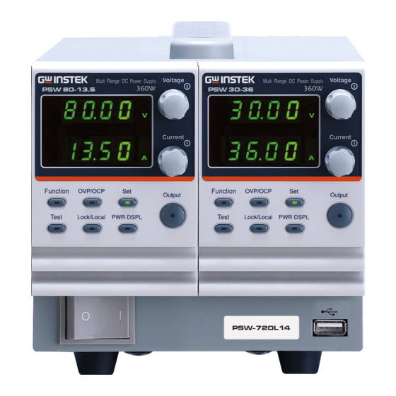
- Page 15 GETTING STARTED PSW-Multi 2-channel modules with low voltage models. Voltage Voltage Multi-Range DC Power Supply Multi-Range DC Power Supply PSW 80-13.5 360W PSW 30-36 360W Current Current Function OVP/OCP Function OVP/OCP Output Output Test Lock/Local PWR DSPL Test Lock/Local PWR DSPL AC 100 240V AC 100...
- Page 16 PSW-Multi Series User Manual PSW-Multi 3-channel modules with low voltage models. Multi-Range DC Power Supply Voltage Multi-Range DC Power Supply Voltage Multi-Range DC Power Supply Voltage PSW 80-13.5 360W PSW 80-13.5 360W PSW 30-36 360W Current Current Current Function OVP/OCP...
-
Page 17: Main Features
GETTING STARTED Main Features Performance High performance/power Power efficient switching type power supply Low impact on load devices Fast transient recovery time of 1ms Fast output response time Features OVP, OCP and OHP (OTP) protection ... -
Page 18: Accessories
PSW-Multi Series User Manual Accessories Please check the contents before using the PSW-Multi. PSW 30/40/80/160 Accessories Standard Accessories Part number Description Power cord (PSW-720) Power cord (PSW-1080) Output terminal Cover (per channel) GTL-123 Test leads: 1x red, 1x black (per... -
Page 19: Psw 250/800 Accessories
GETTING STARTED GRA-410-E Rack mount adapter (EIA) GUG-001 GPIB to USB adapter GTL-240 USB Cable GUR-001A RS-232 to USB adapter with M3 rivet GUR-001B RS-232 to USB adapter with #4-40 UNC rivet nut Download Name Description PSW-Multi_cdc.inf USB driver PSW 250/800 Accessories Standard Accessories Part number Description Power cord (PSW-720) Power cord (PSW-1080) - Page 20 PSW-Multi Series User Manual PSW-003 Contact Removal Tool GRA-410-J Rack mount adapter (JIS) GRA-410-E Rack mount adapter (EIA) GTL-130 Test leads: 2x red, 2x black GUG-001 GPIB to USB adapter GTL-240 USB Cable GUR-001A RS-232 to USB adapter with M3 rivet...
-
Page 21: Appearance
GETTING STARTED Appearance PSW-Multi Front Panel PSW-720 Voltage Voltage Multi-Range DC Power Supply Multi-Range DC Power Supply PSW 30-36 PSW 80-13.5 360W 360W Current Current Function OVP/OCP Function OVP/OCP Output Output Test Lock/Local PWR DSPL Test Lock/Local PWR DSPL PSW-1080 Voltage Voltage Voltage... - Page 22 PSW-Multi Series User Manual 1 Voltage Knob Voltage Sets the voltage. 2 Current Knob Current Sets the current. 3 Output Button Press to turn on the output. The Output Output key will light up when the output is active. 4 Cover panel...
- Page 23 GETTING STARTED Used to run customized scripts for Test testing. Locks or unlocks the panel keys to Lock/Local prevent accidentally changing panel settings. Toggles the display from viewing V/A PWR DSPL V/W or A/W*. *Press the Voltage knob for V/W, press the Current knob for A/W.
-
Page 24: Psw-Multi Rear Panel (Low Voltage Models)
PSW-Multi Series User Manual PSW-Multi Rear Panel (low voltage models) PSW-720 AC 100 240V 63Hz 1000VA MAX. PSW-1080 AC 100 240V 63Hz 1500VA MAX. -
Page 25: Psw-Multi Rear Panel (High Voltage Models)
GETTING STARTED PSW-Multi Rear Panel (high voltage models) PSW-720 S N.C. S S N.C. S AC 100 240V 63Hz 1000VA MAX. PSW-1080 S N.C. S S N.C. S S N.C. S AC 100 240V 63Hz 1500VA MAX. - Page 26 PSW-Multi Series User Manual 1 Ethernet Port The ethernet port is used for remote control and digital monitoring from a 2 Output Terminals Positive (+) and negative (-) (30, 40, 80, 160 output terminals. volt models) Chassis ground Sense (-S) and Sense (+S) terminals.
-
Page 27: Psw-1080
GETTING STARTED current and voltage output. Use an OMRON XG5 IDC socket as the mating socket. 5 Fans Temperature controlled fans 6 Line Voltage Input Voltage Input: 100~240 VAC (PSW-720) Line frequency: 50Hz/60 Hz (Automatically switchable) Line Voltage Input Voltage Input: 100~240 VAC (PSW-1080) ... -
Page 28: Theory Of Operation
PSW-Multi Series User Manual Theory of Operation The theory of operation chapter describes the basic principles of operation, protection modes and important considerations that must be taken into account before use. Operating Area Description Background The PSW power supplies are regulated DC power supplies with a high voltage and current output. - Page 29 GETTING STARTED unit. In this case the output current and voltage then depend purely on the load value. Below is a comparison of the operating areas of each power supply. PSW-Multi 250V, 800V Operating Area 0.45 1.44 … Current (A) …...
-
Page 30: Cc And Cv Mode
PSW-Multi Series User Manual PSW-Multi 30, 40V Operating Area 9 12 13.33 … Current (A) … CC and CV Mode CC and CV mode When the power supply is operating in constant Description current mode (CC) a constant current will be supplied to the load. - Page 31 GETTING STARTED resistance (R ) and the critical resistance (R ). The critical resistance is determined by V . The power supply will operate in CV mode when the load resistance is greater than the critical resistance. This means that the voltage output will be equal to the V voltage but the current will be less than I...
-
Page 32: Slew Rate
PSW-Multi Series User Manual Slew Rate Theory The PSW has selectable slew rates for CC and CV mode. This gives the PSW power supply the ability to limit the current/voltage draw of the power supply. Slew rate settings are divided into High Speed Priority and Slew Rate Priority. - Page 33 GETTING STARTED disconnected. Without a bleed resistor, power may remain charged on the filter capacitors for some time and be potentially hazardous. In addition, bleed resistors also allow for smoother voltage regulation of the power supply as the bleed resistor acts as a minimum voltage load.
-
Page 34: Sink Current Table
PSW-Multi Series User Manual Sink Current Table Background Sink current (reference value) from an external voltage source according to the bleeder circuit setting. PSW 30-36 Bleeder ON Bleeder OFF Vout Sink Current (mA) 1.455 0.000 1.733 0.000 1.559 0.002 1.123 0.009... - Page 35 GETTING STARTED PSW 80-13.5 Bleeder ON Bleeder OFF Vout Sink Current (mA) 0.640 0.002 0.589 0.009 0.488 0.015 0.387 0.026 0.292 0.032 0.224 0.045 0.188 0.058 0.140 0.084 PSW 160-7.2 Bleeder ON Bleeder OFF Vout Sink Current (mA) 0.173 0.009 0.164 0.017 0.146...
-
Page 36: Internal Resistance
PSW-Multi Series User Manual PSW 800-1.44 Bleeder ON Bleeder OFF Vout Sink Current (mA) 0.061 0.056 0.058 0.138 0.054 0.274 0.046 0.550 0.037 0.823 0.029 1.097 0.020 1.653 0.015 2.214 Internal Resistance Background On the PSW, the internal resistance of the power supply can be user-defined in software. -
Page 37: Alarms
GETTING STARTED Alarms The PSW power supplies have a number of protection features. When one of the protection alarms are set, the ALM icon on the display will be lit. For details on how to set the protection modes, please see page 61. Overvoltage protection (OVP) prevents a high voltage from damaging the load. - Page 38 PSW-Multi Series User Manual Cycling the power on and off quickly can cause the Caution inrush current limiting circuit to fail as well as reduce the working life of the input fuse and power switch. Pulsed or Peaked When the load has current peaks or is pulsed, it is...
- Page 39 GETTING STARTED (Ω) ≤ E (V) ÷ I Load The current output will decrease by the amount of Note current absorbed by the dummy resistor. Ensure the resistor used can withstand the power capacity of the power supply/load. Reverse Current: When the power supply is connected to a load Accumulative such as a battery, reverse current may flow back...
-
Page 40: Grounding
PSW-Multi Series User Manual Grounding The output terminals of the PSW power supplies are isolated with respect to the protective grounding terminal. The insulation capacity of the load, the load cables and other connected devices must be taken into consideration when connected to the protective ground or when floating. - Page 41 GETTING STARTED Analog connector Ext-V Load Ext-R ≥ ) Insulation capacity voltage of power supply with respect to ground If using external voltage control, do not ground the CAUTION external voltage terminal as this will create a short circuit.
- Page 42 PSW-Multi Series User Manual PERATION Set Up ..............43 Line Voltage Connection – PSW-1080 Models ......43 Filter Installation ................45 Power Up ..................45 Wire Gauge Considerations ............46 Output Terminals PSW 30/40/80/160 ........47 Using the Output Terminal Cover PSW 30/40/80/160 ..49 Output Terminals PSW 250/800 ..........
-
Page 43: Operation
The PSW-1080 models use a universal power input that can be used with 100 and 200 VAC systems. To connect or replace the power cord (GW Instek part number: 4320-91001101, use the procedure below: The following procedure should only be attempted by Warning competent persons. - Page 44 PSW-Multi Series User Manual 4. Slide the cover off the AC terminals. 5. Remove the AC power cord wires. Installation 1. Connect the AC power cord wires to the AC input terminals. White/Blue Neutral (N) Green/Green- yellowGND ( Black/Brown ...
-
Page 45: Filter Installation
OPERATION Filter Installation Background The PSW has a small filter (GW Instek part number, 57RG-30B001X1) that must first be inserted under the control panel before operation. The small filter must be inserted for all model types. Steps 1. Insert the small filter in the open area under the control panel. -
Page 46: Wire Gauge Considerations
PSW-Multi Series User Manual The power supply takes around 8 seconds to fully CAUTION turn on and shutdown. Do not turn the power on and off quickly. Please wait for the display to fully turn off. Wire Gauge Considerations Background... -
Page 47: Output Terminals Psw 30/40/80/160
OPERATION The maximum temperature rise can only be 60 degrees above the ambient temperature. The ambient temperature must be less than 30 deg. Output Terminals PSW 30/40/80/160 Background Before connecting the output terminals to the load, first consider whether voltage sense will be used, the gauge of the cable wiring and the withstand voltage of the cables and load. - Page 48 PSW-Multi Series User Manual 5. Choose a suitable crimp for the terminals. Page 70 6. If using voltage sense, remove the sense terminal joining plates and connect sensing wires to the load(s). 7. Connect the positive load cable to the positive output terminal and the negative cable to the negative output terminal.
-
Page 49: Using The Output Terminal Cover Psw 30/40/80/160
OPERATION Using the Output Terminal Cover PSW 30/40/80/160 Steps 1. Remove the screw holding the top cover to the bottom cover. 2. Line-up the bottom cover with the notches in the output terminals. 3. Place the top terminal cover over the bottom cover. -
Page 50: Output Terminals Psw 250/800
PSW-Multi Series User Manual Output Terminals PSW 250/800 Background The high voltage models (PSW 250 and PSW 800 models) use a 9 pin socket for the output voltage and sense connections. The corresponding plugs (GW part number PSW-012 //DECA SwitchLab MC420-38109Z) should be used to connect the terminals to the appropriate cable. - Page 51 OPERATION Output Connector -V: -V terminals Pinout (x3) -S: -Sense terminal NC: Not connected +S: +Sense terminal N.C. +V: +V terminals (x3) Wiring the a. Unscrew the Loosen Connector Plug appropriate terminal Tighten anticlockwise to release the receptacle. b. Insert a wire that has had at least ~7mm stripped from the insulation.
- Page 52 PSW-Multi Series User Manual Please note the wire gauge used and the capacity of WARNING the plug/socket. It may be necessary to wire the load to a number of terminals to offset the capacity over a number of terminals. 6. If using local sense, connect the -S pin to a -V pin, and connect the +S pin to a +V pin.
- Page 53 OPERATION Local Sense Wiring To negative potential To positive potential Remote Sense Wiring To negative potential To positive potential...
-
Page 54: Using The Output Terminal Cover Psw 250/800
PSW-Multi Series User Manual Using the Output Terminal Cover PSW 250/800 Steps 1. Screw the bottom cover onto the rear panel using the two M4 screws. 2. Slide the top cover over the bottom cover. 3. Finally, secure the top cover with the screw in the center of the top cover. -
Page 55: Using The Rack Mount Kit
Using the Rack Mount Kit Background The PSW series has an optional Rack Mount Kit (GW Instek part number: [JIS] GRA-410-J, [EIA] GRA-410-E[EIA]) that can be used to hold 6x PSW models, 3x PSW-720 models, 2x PSW-1080 models or a combination of all models (1x PSW, 1x PSW- 720 and 1x PSW-1080). - Page 56 PSW-Multi Series User Manual 1. Repeatedly press the Voltage knob until the last digit is highlighted. Voltage This will allow the voltage to be edited in 0.01 volt steps. 2. Turn the Voltage knob till 0.05 Voltage volts is shown.
-
Page 57: Reset To Factory Default Settings
OPERATION Reset to Factory Default Settings Background The F-88 configuration setting allows the PSW to be reset back to the factory default settings. See page 143 for the default factory settings. Steps 1. Press the Function key. The Function Function key will light up. 2. -
Page 58: View System Version And Build Date
PSW-Multi Series User Manual View System Version and Build Date Background The F-89 configuration setting allows you to view the PSW version number, build date, keyboard version, analog-control version, kernel build, test command version, test command build date, and the USB driver version. - Page 59 OPERATION 9-XX: Analog CPLD version. A-XX: Control Board Version. B-XX: Reserved. C-XX: Kernel Build On-Year. D-XX: Kernel Build On-Year. E -XX: Kernel Build On-Month. F-XX: Kernel Build On-Day. G-XX: Test Command Version. H-XX: Test Command Version. I-XX: Test Command Build On-Year. J-XX: Test Command Build On-Year.
- Page 60 PSW-Multi Series User Manual C-20: Kernel Build On-Year. D-13: Kernel Build On-Year. E-03: Kernel Build On-Month. F-22: Kernel Build On-Day. Example Test Command Version: V01:00, 2011/08/01 G-01: Test Command Version. H-00: Test Command Version. I-20: Test Command Build On-Year. J-11: Test Command Build On-Year.
-
Page 61: Basic Operation
OPERATION Basic Operation This section describes the basic operations required to operate the power supply. Setting OVP/OCP → from page 61 C.V. mode → from page 62 C.C. mode → from page 66 Display modes → page 69 ... - Page 62 PSW-Multi Series User Manual Before setting the OVP or OCP level: Ensure the load is not connected. Ensure the output is set to off. Setting Ranges 30-36 40-27 80-13.5 160-7.2 250-4.5 800-1.44 OVP Range (V) 3-33 4-44 8-88...
-
Page 63: Set To C.v. Mode
OPERATION 5. Press OVP/OCP again to exit. The OVP/OCP OVP/OCP indicator will turn off. Power switch trip Set F-95 (Power switch trip) to 1 (to Page 98 disable the power switch trip) or to 0 (to enable the power switch trip) and save. - Page 64 PSW-Multi Series User Manual Background Before setting the power supply to C.V. mode, ensure: The output is off. The load is connected. Steps 1. Press the Function key. The Function Function key will light up. 2. The display should show F-...
- Page 65 OPERATION 6. If CV Slew Rate Priority was chosen as the operating mode, repeat steps 3~5 to set F-04 (Rising Voltage Slew Rate) and the F-05 (Falling Voltage Slew Rate) and save. F-04 / F-05 0.1V/s ~ 60V/s (PSW 30) 0.1V/s ~ 80V/s (PSW 40) 0.1V/s ~ 160V/s (PSW 80) 0.1V/s ~ 320V/s (PSW 160)
-
Page 66: Set To C.c. Mode
PSW-Multi Series User Manual Only the voltage level can be altered when the output Note is on. The current level can only be changed by pressing the Set key. For more information on the Normal Function Settings (F-00 ~ F-61, F-88~F-89) see page 87. - Page 67 OPERATION Current 4. Use the Current knob to set the F-03 setting. Set F-03 to 1 (CC High Speed Priority) or 3 (CC Slew Rate Priority) and save. F-03 1 = CC High Speed Priority 3 = CC Slew Rate Priority 5.
- Page 68 PSW-Multi Series User Manual Current 9. Use the Current knob to set the current. Notice the Set key becomes illuminated when setting Note the current or voltage. If the Voltage or Current knobs are unresponsive, press the Set key first.
-
Page 69: Display Modes
OPERATION Display Modes The PSW power supplies allow you to view the output in three different modes: voltage and current, voltage and power or current and power. Steps 1. Press the PWR/DSPL key. The PWR DSPL PWR DSPL key lights up. 2. -
Page 70: Panel Lock
PSW-Multi Series User Manual Panel Lock The panel lock feature prevents settings from being changed accidentally. When activated, the Lock/Local key will become illuminated and all keys and knobs except the Lock/Local key and Output key (if active) will be disabled. - Page 71 OPERATION Be sure to remove the Sense joining plates so the Note units are not using local sensing. Single Load 1. Connect the Sense+ terminal to the positive potential of the load. Connect the Sense- terminal to the negative potential of the load. Load Page 47 Output...
-
Page 72: Test Scripts
The PSW test function can store ten test scripts in memory. Each test script is programmed in a scripting language. For more information on how to create test scripts, please contact GW Instek. Test Script File Format→ from page 73 ... -
Page 73: Test Script File Format
OPERATION Test Script File Format Background The test files are saved in *.tst file format. Each file is saved as tXXX.tst, where XXX is the save file number 001~010. Test Script Settings Test Run Runs the chosen test script from the internal memory. -
Page 74: Setting The Test Script Settings
PSW-Multi Series User Manual Setting the Test Script Settings Steps The test script settings (T-01~T-04) are set with the Test key. 1. Press the Test key. The Test key will Test light up. 2. The display will show T-01 on the top and the memory no. -
Page 75: Load Test Script From Usb
OPERATION 4. Rotate the Current knob to choose a Current memory number. Range 1~10 5. Press the Voltage knob to complete the setting. Voltage Exit Press the Test key again to exit the Test Test settings. The Test key light will turn off. - Page 76 PSW-Multi Series User Manual 2. Turn on the power. MS (Mass Storage) will be displayed on the screen after a few seconds if the USB drive is recognized. If the USB drive is not recognized, check to see that Note the function settings for F-20 = 1 (page 91).
-
Page 77: Run Test Script (Manual)
OPERATION Run Test Script (Manual) Overview A test script can be run from one of ten memory slots. Steps Page 75 1. Before a test script can be run, it must first be loaded into one of the 10 memory save slots. Page 74 2. - Page 78 PSW-Multi Series User Manual 4. If there are no errors during loading, the script engine will enter the wait state. The wait state indicates that the unit is ready to execute the script. Wait state 5. To execute the script, press the Output Output key.
-
Page 79: Run Test Script (Automatically At Startup)
OPERATION Run Test Script (Automatically at Startup) Overview The power supply can be configured to automatically run a test script at startup. Steps Page 75 1. Before a test script can be run, it must first be loaded into one of the 10 memory save slots. -
Page 80: Export Test Script To Usb
PSW-Multi Series User Manual Export Test Script to USB Overview The Export Test function saves a test file to the root directory of a USB flash drive. Files will be saved as tXXX.tst where XXX is the memory number 001~010 from which the test script was exported from. -
Page 81: Remove Test Script
OPERATION Error messages: If you try to export a test script from Note an empty memory location “Err 003” will be displayed on the display. Remove Test Script Overview The Remove Test function will delete a test script from the internal memory. Steps Page 74 1. -
Page 82: Checking The Available Memory
PSW-Multi Series User Manual Checking the Available Memory Overview The T-05 function displays the amount of internal memory that is left on the unit to load test scripts. The displayed units are in kilobytes (1024 bytes). Steps Page 74 Select T-05 (Test Memory). The available memory in kilobytes is displayed. -
Page 83: Configuration
CONFIGURATION ONFIGURATION Configuration ............84 Configuration Table ............... 84 Normal Function Settings ............. 88 USB/GPIB Settings ..............92 LAN Settings ................. 93 System Settings ................94 Power On Configuration Settings ..........95 Multi-Channel Function Setting ........... 96 Calibration ..................97 Setting Normal Function Settings .......... -
Page 84: Configuration
PSW-Multi Series User Manual Configuration Configuration of the PSW power supplies is divided into six different configuration settings: Normal Function, USB/ GPIB/ RS232, LAN, Power ON Configuration, Calibration Setting, Multi- channel Function setting and System settings. Power ON Configuration differs from the other settings in that the settings used with Power ON Configuration settings can only be set during power up. - Page 85 CONFIGURATION 0.01A/s ~ 72.00A/s (PSW 30-36) 0.01A/s ~ 54.00A/s (PSW 40-27) 0.01A/s ~ 27.00A/s (PSW 80-13.5) Rising current slew rate F-06 0.01A/s ~ 14.40A/s (PSW 160-7.2) 0.001A/s ~ 9.000A/s (PSW 250-4.5) 0.001A/s ~ 2.880A/s (PSW 800-1.44) 0.01A/s ~ 72.00A/s (PSW 30-36) 0.01A/s ~ 54.00A/s (PSW 40-27) 0.01A/s ~ 27.00A/s (PSW 80-13.5) Falling current slew rate...
- Page 86 PSW-Multi Series User Manual DHCP F-37 0 = Disable, 1 = Enable IP Address-1 F-39 0 ~ 255 IP Address-2 F-40 0 ~ 255 IP Address-3 F-41 0 ~ 255 IP Address-4 F-42 0 ~ 255 Subnet Mask-1 F-43 0 ~ 255...
- Page 87 CONFIGURATION C, D = Kernel build year E, F = Kernel build month/day G, H = Test command version I, J = Test command build year K, L = Test command build month/ M, N = USB Driver version. Power On Configuration Settings 0 = Panel control (local) 1 = External voltage control 2 = External resistance control...
-
Page 88: Normal Function Settings
PSW-Multi Series User Manual Enter configuration setting from CH1 and each channel can be used different settings. Under normal operation they only can be viewed. : Need to be used together with GUR-001 series. Normal Function Settings Output ON Delay... - Page 89 CONFIGURATION V-I Mode Selects High Speed Priority or Slew Rate Priority for CV or CC mode. The voltage or current slew rate can only be edited if CC/CV Slew Rate Priority is selected. The ISR indicator will be lit for CC Slew Rate Priority and the VSR indicator will be lit for CV Slew Rate Priority.
- Page 90 PSW-Multi Series User Manual Rising Current Sets the rising current slew rate. Only applicable if Slew Rate V-I Mode is set to CC Slew Rate Priority. F-06 0.01A/s ~ 72.00A/s (PSW 30-36) 0.01A/s ~ 54.00A/s (PSW 40-27) 0.01A/s ~ 27.00A/s (PSW 80-13.5) 0.01A/s ~ 14.40A/s (PSW 160-7.2)
- Page 91 CONFIGURATION The AUTO setting is only applicable to firmware version 1.59 or above. The following table shows how the state of the bleeder resistor depends on the Bleeder Control settings, the power state and the output state. Bleeder Control Setting F-09 0 = OFF 1 = ON 2 = AUTO...
-
Page 92: Usb/Gpib Settings
PSW-Multi Series User Manual USB/GPIB Settings Front Panel USB Displays the front panel USB-A port state. This State setting is not configurable. F-20 0 = Absent, 1 = Mass Storage Displays the rear panel USB-B port state. This Rear Panel USB setting is not configurable. -
Page 93: Lan Settings
CONFIGURATION LAN Settings MAC Address- Displays the MAC address 1~6. This setting is not configurable. F-30~F-35 0x00~0xFF Turns Ethernet on or off. F-36 0 = Disable, 1 = Enable DHCP Turns DHCP on or off. F-37 0 = Disable, 1 = Enable IP Address-1~4 Sets the default IP address. -
Page 94: System Settings
PSW-Multi Series User Manual Web Password Turns a web password on/off. active F-60 0 = Disable, 1 = Enable Web Password Sets the Web password. F-61 0000 ~ 9999 *: Only configure from CH1 System Settings Factory Set Value Returns the PSW to the factory default settings. See page 143 for a list of the default settings. -
Page 95: Power On Configuration Settings
CONFIGURATION Power On Configuration Settings CV Control Sets the constant voltage (CV) control mode between local and external voltage/resistance control. For external voltage control, see page 103 (External Voltage Control of Voltage Output) and page 108(External Resistance Control of Voltage Output). -
Page 96: Multi-Channel Function Setting
PSW-Multi Series User Manual External Out Logic Sets the external logic as active high or low. F-94 0= High ON, 1 = Low ON Power Switch Trip Turns the power off if enabled when the protection settings are tripped. F-95... -
Page 97: Calibration
CONFIGURATION Calibration Programmable The calibration password is used to access the Calibration local mode calibration or other special functions. The password used determines which function is accessed. Please see your distributor for details. F-00 0000 ~ 9999 Setting Normal Function Settings Background The normal function settings (F-01 ~ F-61, F88 ~ F89 and F130 ~ F132) can be easily configured... -
Page 98: Setting Power On Configuration Settings
PSW-Multi Series User Manual Range F-00 ~ F-61, F-88 ~ F-89 and F130 ~ F132 Current 4. Use the Current knob to set the parameter for the chosen F setting. 5. Press the Voltage knob to save the configuration setting. ConF will be Voltage displayed when successful. - Page 99 CONFIGURATION Voltage 3. Rotate the voltage knob to change the F setting on each channel. F-90~ F-95 Current 4. Use the Current knob to set the parameter for the chosen F setting. 5. Press the Voltage knob to save the configuration setting.
- Page 100 PSW-Multi Series User Manual NALOG CONTROL The Analog Control chapter describes how to control the voltage or current output using an external voltage or resistance, monitor the voltage or current output as well as remotely turning off the output or shutting down the power supply.
-
Page 101: Analog Control
ANALOG CONTROL Analog Remote Control Overview The PSW power supply series have a number of analog control options. The Analog Control connectors are used to control output voltage and current using external voltage or resistance. The power supply output and power switch can also be controlled using external switches. - Page 102 TTL signal is applied. The shutdown signal is pulled up to 5V with a 10kΩ pull-up resistor. CURRENT_SUM_1 13 No supported on PSW-Multi series. CURRENT_SUM_2 14 No supported on PSW-Multi series. FEEDBACK 15 No supported on PSW-Multi series.
-
Page 103: External Voltage Control Of Voltage Output
24 Turns the output on/off when (default setting) a CONT low TTL signal is applied. Internally, the circuit is pulled up to +5V with 10kΩ resistance. SER SLV IN 25 No supported on PSW-Multi series. N.C. 26 Not connected External Voltage Control of Voltage Output Background... - Page 104 PSW-Multi Series User Manual Connection When connecting the external voltage source to the MIL connectors, use shielded or twisted paired wiring. EXT-V + Analog connector - 2 core shielded wire or twisted Output pair Terminal Pin16 → EXT-V (-) ...
- Page 105 ANALOG CONTROL 2. Set the F-90 power on Page 98 configuration setting to 1 (CV control – Ext voltage). Be sure to cycle the power after the power on configuration has been set. 3. Press the Function key and confirm Function the new configuration settings (F-90=1).
-
Page 106: External Voltage Control Of Current Output
PSW-Multi Series User Manual External Voltage Control of Current Output Background External voltage control of the current output is accomplished using the MIL-26 connector on the rear panel. A voltage of 0~10V is used to control the full scale current of the instrument, where: Output current = full scale current ×... - Page 107 ANALOG CONTROL Connection- alt. If the wire shield needs to be grounded at the shielding voltage source (EXT-V), then the shield cannot also be grounded at the negative (-) terminal output of the PSW power supply. This would short the output. EXT-V +...
-
Page 108: External Resistance Control Of Voltage Output
PSW-Multi Series User Manual The input impedance for external voltage control is Note 10kΩ. Use a stable voltage supply for the external voltage control. CV and CC Slew Rate Priority are disabled for V-I Note mode (F-03) when using external voltage control. See the normal function settings on page 87. - Page 109 ANALOG CONTROL The Ext-R configuration is recommended for safety Note reasons. In the event that the cables become accidentally disconnected, the voltage output will drop to zero. Under similar circumstances using Ext- , an unexpected high voltage would be output. If switches are used to switch between fixed resistances, use switches that avoid creating open circuits.
-
Page 110: External Resistance Control Of Current Output
PSW-Multi Series User Manual 4. Press the Output key. The voltage Output can now be controlled with the External resistance. Ensure the resistor(s) and cables used exceed the Note isolation voltage of the power supply. For example: insulation tubes with a withstand voltage higher than the power supply can be used. - Page 111 ANALOG CONTROL The Ext-R configuration is recommended for safety Note reasons. In the event that the cables become accidentally disconnected, the current output will drop to zero. Under similar circumstances using Ext- , an unexpected high current would be output. If switches are used to switch between fixed resistances, use switches that avoid creating open circuits.
-
Page 112: External Control Of Output
PSW-Multi Series User Manual 3. Press the Output key. The current Output can now be controlled with the External resistance. Ensure the resistor(s) and cables used exceed the Note isolation voltage of the power supply. For example: insulation tubes with a withstand voltage higher than the power supply can be used. - Page 113 ANALOG CONTROL Switch Connection Analog connector 2 core shielded wire or twisted Output pair Terminal Pin2 → Switch Pin24 → Switch Wire shield → negative (-) output terminal Steps 1. Connect the external switch according to the connection diagrams above.
- Page 114 PSW-Multi Series User Manual When using a switch over long distances, please use a Note switch relay to extend the line from the coil side of the relay. Switch Relay Line Analog connector extension If a single switch control is to be used for Multiple units, please isolate each instrument.
-
Page 115: External Control Of Shutdown
ANALOG CONTROL External control of Shutdown Background The output of the power supplies can be configured to shut down via an external switch. The ability to externally shut down the power supply must first be enabled in the power on configuration settings. - Page 116 PSW-Multi Series User Manual When using a switch over long distances, please use a Note switch relay to extend the line from the coil side of the relay. Switch Relay Line Analog connector extension If a single switch control is to be used for Multiple units, please isolate each instrument.
-
Page 117: Remote Monitoring
ANALOG CONTROL Remote Monitoring The PSW power supplies have remote monitoring support for current and voltage output. They also support monitoring of operation and alarm status. External monitoring of output voltage and current → from page External monitoring of operation mode and alarm status → from ... - Page 118 PSW-Multi Series User Manual IMON Connection Analog connector I MON → Output Terminal Pin16 → Neg (-) Pin11 → Pos (+) The output impedance of the voltage (VMON) and Note current (IMON) monitor pins is 1kΩ. Maximum current is 10mA.
-
Page 119: External Operation And Status Monitoring
ANALOG CONTROL External Operation and Status Monitoring Background The MIL 26 pin connector can also be used to monitor the status operation and alarm status of the instrument. The pins are isolated from the power supply internal circuitry by photo couplers. Status Com (Pin 17) is a photo coupler emitter output, whilst pins 18~22 are photo coupler collector outputs. - Page 120 PSW-Multi Series User Manual CV MODE: The diagram below shows the timing diagram Output turned on when the output is turned on when the PSW is set to CV mode. CV status CC status Output status CV MODE: The diagram below shows the output status lines Output turned off when the output is turned off in CV mode.
- Page 121 ANALOG CONTROL CC MODE: The diagram below shows the output status lines Output turned off when the output is turned off in CC mode. CV status CC status Output status...
- Page 122 PSW-Multi Series User Manual OMMUNICATION INTERFACE This chapter describes basic configuration of IEEE488.2 based remote control. For a command list, refer to the programming manual, downloadable from GW Instek website, www.gwinstek.com Interface Configuration ........... 123 Configure USB Remote Interface ..........123 Configure GPIB Interface ............
-
Page 123: Communication Interface
COMMUNICATION INTERFACE Interface Configuration Configure USB Remote Interface PC side connector Type A, host configuration PSW side Rear panel Type B, slave connector Speed 1.1/2.0 (full speed/high speed) USB Class CDC (communications device class) Panel operation 1. Connect the USB cable to the rear panel USB B port. - Page 124 PSW-Multi Series User Manual 3. Connect a GPIB cable from a GPIB controller to the GPIB port on the adapter. Type A plug From computer Type B plug for PSW series GUG-001 4. Turn the PSW on. 5. Press the Function key to enter the Normal configuration settings.
-
Page 125: Configure Ethernet Connection
COMMUNICATION INTERFACE Configure Ethernet Connection The Ethernet interface can be configured for a number of different applications. Ethernet can be configured for basic remote control or monitoring using a web server or it can be configured as a socket server. The PSW Series supports both DHCP connections so the instrument can be automatically connected to an existing network or alternatively, network settings can be manually configured. -
Page 126: Sockets Server Configuration
PSW-Multi Series User Manual It may be necessary to cycle the power or refresh the Note web browser to connect to a network. Sockets Server Configuration Configuration This configuration example will configure the PSW sockets server. The following configuration settings will manually assign the PSW an IP address and enable the socket server. -
Page 127: Usb Remote Control Function Check
Serial number, and Firmware version in the following format. PSW30-36 GW-INSTEK, ,TW123456,01.00.20110101 Manufacturer: GW-INSTEK Model number : PSW30-36 Serial number : TW123456 Firmware version : 01.00.20110101 For further details, please see the programming Note manual, available on the GW Instek web site @ www.gwinstek.com. -
Page 128: Using Realterm To Establish A Remote Connection
PSW-Multi Series User Manual Using Realterm to Establish a Remote Connection Background Realterm is a terminal program that can be used to communicate with a device attached to the serial port of a PC or via an emulated serial port via USB. - Page 129 COMMUNICATION INTERFACE 4. Start Realterm on the PC as an administrator. Click: Start menu>All Programs>RealTerm>realterm Tip: to run as an administrator, you can right click the Realterm icon in the Windows Start menu and select the Run as Administrator option. 5.
-
Page 130: Gpib Remote Control Function Check
PSW-Multi Series User Manual 6. Click on the Send tab. In the EOL configuration, check on the +CR and +LF check boxes. Enter the query: *idn? Click on Send ASCII. 7. The terminal display will return the following: GW-INSTEK,PSW250-9,,01.54.20140313 (manufacturer, model, serial number, version) 8. - Page 131 COMMUNICATION INTERFACE Once NI-VISA is installed, please download NI- 488.2 and complete the installation. NI-488.2 can be downloaded from the NI website www.ni.com. Please search for “NI-488.2 download” on the NI website to obtain it. The following function check is based on version 2022 Q3.
- Page 132 PSW-Multi Series User Manual 5. Click on Communicate with Instrument. 6. In the NI-488.2 Communicator window, ensure *IDN? is written in the Send String: text box. Click on the Query button to send the *IDN? query to the oscilloscope. 7. The String Received text box will display the query return: GW-INSTEK,PSW250-9,,01.54.20140313\n...
-
Page 133: Web Server Remote Control Function Check
(page 125). http:// XXX.XXX.XXX.XXX The web browser interface appears. For further details, please see the programming Note manual, available on the GW Instek web site @ www.gwinstek.com. Socket Server Function Check Background To check if the socket server connection is... - Page 134 PSW-Multi Series User Manual 2. From the Configuration panel access; My System>Devices and Interfaces>Network Devices 3. Click Create New..4. Select Visa TCP/IP Resource. 5. Select Manual Entry of Raw Socket from the popup window. 6. Click Next.
- Page 135 COMMUNICATION INTERFACE 7. Enter the IP address and the port number of the PSW. The port number is fixed at 2268. 8. Click the Validate button. A popup box will appear when successful. 9. Click Next. 10. Next configure the Alias (name) of the PSW connection.
- Page 136 PSW-Multi Series User Manual 13. Press Open VISA Test Panel. 14. Click Configuration icon. 15. In the I/O Settings tab, select the Enable Termination Character check box. Ensure Line Feed - \n is selected as the line feed character. 16. Click Apply Changes.
- Page 137 COMMUNICATION INTERFACE For further details, please see the programming Note manual, available on the GW Instek web site @ www.gwinstek.com.
- Page 138 PSW-Multi Series User Manual AINTENANCE The PSW power supply filters should be replaced on a periodic schedule to maintain performance and specification characteristics. Replacing the Dust Filter ............139...
-
Page 139: Maintenance
Front panel filter 1. Turn the instrument off. (all models) 2. Pull the filter out from the bottom of the front panel. 3. Replace the filter with GW Instek part number 57RG-30B03801. -
Page 140: Faq
PSW-Multi Series User Manual • The power supply won’t let me change the mode (C.V. mode ↔ C.C. mode). • The OVP voltage is triggered earlier than expected. • Can I combine more than 1 cable together for the output wiring? •... - Page 141 The accuracy does not match the specification. Make sure the device is powered On for at least 30 minutes, within +20°C~+30°C. This is necessary to stabilize the unit to match the specification. For more information, contact your local dealer or GWInstek at www.gwinstek.com / marketing@goodwill.com.tw.
- Page 142 PSW-Multi Series User Manual PPENDIX PSW-Multi Web Control Description ....... 143 Tab Welcome Page ..............143 Tab Network Configuration ............ 144 Tab SCPI command ..............144 Tab Web control ................. 144 Tab Data log ................149 Tab Edit Sequence ..............150 Tab Visit Our Site ..............
-
Page 143: Appendix
APPENDIX PSW-Multi Web Control Description Open the web browser and input the IP address of PSW-Multi and then push “Enter key” to move over to Web Control server. There are seven tabs on the top of the Web Control Page. Select the tab you desire on the top of the Web control page by clicking the mouse so that you can control the PSW-Multi or get more information about it. -
Page 144: Tab Network Configuration
PSW-Multi Series User Manual Tab Network Configuration On the Network Configuration page, user can change the IP Address, Subnet Mask, Gateway, DNS address or set password or set DHCP enable to get all network settings from router. Tab SCPI command On SCPI command page, user can use SCPI command to remote control PSW-Multi. - Page 145 APPENDIX Channel display Model type This indicator is for indicating Voltage Slew Rate signal. If VSR function is enabled, the signal will become green. Constant Voltage Mode signal. If PSW-Multi operates in constant voltage mode, the signal will become green. Delay Output signal.
- Page 146 PSW-Multi Series User Manual SET Table: User can set Voltage and current setting or adjust the setting step unit in this table. PROT Table: User can set OVP and OCP setting in this table FUNC_NORMAL Table: User can set function...
- Page 147 APPENDIX FUNC_USB/GPIB/UART Table: User can set interface setting in this table. FUNC_PON CONF Table: User can set power on configuration setting in this table. Be sure to cycle the power after the power on configuration has been set.
- Page 148 PSW-Multi Series User Manual TEST Table: User can use test script function in this table. LOCK/UNLOCK Table: User can use lock or unlock function in this table. PWR DSPL Table: User can choose display mode to change Voltage/ Current/ Power display setting in this table.
-
Page 149: Tab Data Log
APPENDIX Tab Data log On Data log page, user can set data log function to record the output voltage and output current by period sampling time and counter setting. For usage of data log record function, please follow the setting description. -
Page 150: Tab Edit Sequence
PSW-Multi Series User Manual Current: measurement current value. OPER. Status: Value of operation Status Register. Please refer to programming manual for a detail description. QUES. Status: Value of questionable Status Register Value. Please refer to programming manual for a detail description. - Page 151 APPENDIX When sequence editing is complete, user can upload sequence to PSW-Multi. There are ten groups sequence can be uploaded. If there is any sequence already that has been uploaded, the group will be displayed in dark black. Export sequence to CSV format and generate .tst attachment.
-
Page 152: Tab Visit Our Site
PSW-Multi Series User Manual When user wants to edit sequence, user can move mouse flag to everywhere which he wants to edit and press mouse button. Then description field will show description and setting range, user can take a reference and edit it. -
Page 153: Psw-Multi Default Settings
APPENDIX PSW-Multi Default Settings The following default settings are the factory configuration settings for the power supply (Function settings/Test settings). For details on how to return to the factory default settings, see page Default Setting Initial Settings Output LOCK 0 (Disabled) Voltage Current Maximum... - Page 154 PSW-Multi Series User Manual Falling current slew rate F-07 72.00A/s (PSW 30-36) 54.00A/s (PSW 40-27) 27.00A/s (PSW 80-13.5) 14.40A/s (PSW 160-7.2) 9.000A/s (PSW 250-4.5) 2.880A/s (PSW 800-1.44) Internal resistance setting F-08 0.000Ω Bleeder circuit control F-09 1 = ON Buzzer ON/OFF control...
-
Page 155: Error Messages & Messages
APPENDIX Error Messages & Messages The following error messages or messages may appear on the PSW screen during operation. Error Messages Description Err 001 USB Mass Storage is not present Err 002 No (such)file in USB mass storage Err 003 Empty memory location Err 004 File access error... -
Page 156: Specifications
PSW-Multi Series User Manual Specifications The specifications apply when the PSW is powered on for at least 30 minutes. PSW 30-36, PSW 40-27, PSW 80-13.5, PSW 160-7.2, PSW 250-4.5, PSW 800-1.44 Model Unit 30-36 40-27 80-13.5 160-7.2 250-4.5 800-1.44 Rated Output Voltage Rated Output Current 13.5... - Page 157 APPENDIX Protection Function Over voltage protection (OVP) Setting range V 3-33 4-44 8-88 16-176 20-275 20-880 Setting accuracy ± (2% of rated output voltage) Over current protection (OCP) Setting range 3.6- 2.7- 1.35- 0.72- 0.45- 0.144- 39.6 29.7 14.85 7.92 4.95 1.584 Setting accuracy...
- Page 158 PSW-Multi Series User Manual Front Panel Display, 4 digits Voltage accuracy 0.1% + mV 20 Current accuracy 0.1% + mA 40 Indications GREEN LED's: CV, CC, VSR, ISR, DLY, RMT, 20, 40, 60, 80, 100, %W, W, V, A RED LED's: ALM...
-
Page 159: 159
APPENDIX PSW-720 Input Characteristics Nominal input rating 100Vac to 240Vac, 50Hz to 60Hz, single phase Input voltage range 85Vac ~ 265Vac Input voltage range 47Hz ~ 63Hz Maximum input current 100Vac 200Vac Inrush current Less than 50A. Maximum input power VA 1000 Power factor 100Vac... -
Page 160: Psw-1080
PSW-Multi Series User Manual Between output and chassis: No abnormalities at 500 Vdc for 1 minute for 30V, 40, 80V, 160V models. No abnormalities at 1500 Vdc for 1 minute for 250V, 800V models. Insulation resistance Between input and chassis: 500 Vdc, 100MΩ... - Page 161 APPENDIX General Specifications Weight (main unit only) kg Approx. 7.7kg Dimensions (W x H x D) mm 214 x 124 x 350 Cooling Forced air cooling by internal fan. Complies with the European EMC directive for Class A test and measurement products. Safety Complies with the European Low Voltage Directive and carries the CE-marking.
-
Page 162: Psw-Multi Dimensions
PSW-Multi Series User Manual PSW-Multi Dimensions PSW-720 PSW 250-4.5/ PSW 800-1.44 (scale: mm) -
Page 163: Psw 160-7.2/ Psw 80-13.5/ Psw 40-27/ Psw 30-36 (Scale: Mm)
APPENDIX PSW 160-7.2/ PSW 80-13.5/ PSW 40-27/ PSW 30-36 (scale: mm) Part A, Ratio 2:1 For details, check part A... -
Page 164: Psw-1080
PSW-Multi Series User Manual PSW-1080 PSW 250-9/ PSW 800-2.88 (scale: mm) -
Page 165: Psw 160-14.4/ Psw 80-27/ Psw 40-54/ Psw 30-72 (Scale: Mm)
APPENDIX PSW 160-14.4/ PSW 80-27/ PSW 40-54/ PSW 30-72 (scale: mm) Part A, Ratio 2:1 For details, check part A... -
Page 166: Certificate Of Compliance
PSW-Multi Series User Manual Certificate Of Compliance GOOD WILL INSTRUMENT CO., LTD. declare that the CE marking mentioned product satisfies all the technical relations application to the product within the scope of council: Directive: EMC; LVD; WEEE; RoHS The product is in conformity with the following standards or other normative documents: ◎... -
Page 167: Index
INDEX NDEX table ..........84 Accessories ......... 18 test function settings ....74 Alarm USB/GPIB settings ....... 92 description ........37 Connector plug manufacturer26, 50 Analog connector Conventions ........ 55 pin assignment ......101 CV mode Analog control operation ........64 output control ...... - Page 168 PSW-Multi Series User Manual operation ........70 Load connection Service operation PSW-250/800 ......... 50 PSW-30/40/80/160 ...... 47 about disassembly ......6 Maintenance contact .......... 141 Slew rate replacing the filter ...... 139 Marketing description ........32 Socket server function check .. 133 contact ..........
Need help?
Do you have a question about the PSW-Multi Series and is the answer not in the manual?
Questions and answers