
Related Manuals for HIKVISION NS-0318P Series


Summary of Contents for HIKVISION NS-0318P Series
- Page 1 16/24-Port 100M Long-Range PoE Switch Quick Start Guide 16/24-Port 100M Long-Range PoE Switch Quick Start Guide...
- Page 2 INDIRECT DAMAGES, INCLUDING, AMONG OTHERS, DAMAGES FOR LOSS OF BUSINESS PROFITS, BUSINESS INTERRUPTION, OR LOSS OF DATA OR DOCUMENTATION, IN CONNECTION WITH THE USE OF THIS PRODUCT, EVEN IF HIKVISION HAS BEEN ADVISED OF THE POSSIBILITY OF SUCH DAMAGES. REGARDING TO THE PRODUCT WITH INTERNET ACCESS, THE USE OF PRODUCT SHALL BE WHOLLY AT YOUR OWN RISKS.
- Page 3 16/24-Port 100M Long-Range PoE Switch Quick Start Guide Regulatory Information FCC Information Please take attention that changes or modification not expressly approved by the party responsible for compliance could void the user’s authority to operate the equipment. FCC compliance: This equipment has been tested and found to comply with the limits for a Class A digital device, pursuant to part 15 of the FCC Rules.
-
Page 4: Applicable Models
16/24-Port 100M Long-Range PoE Switch Quick Start Guide Applicable Models This manual is applicable to switches below: NS-0318P & NS-0326P series. Symbol Conventions The symbols that may be found in this document are defined as follows. Symbol Description Provides additional information to emphasize or supplement important points of the main text. -
Page 5: Chapter 1 Introduction
16/24-Port 100M Long-Range PoE Switch Quick Start Guide Chapter 1 Introduction 1.1 Overview NS-0318P-130(B) and NS-0326P-230(B) unmanaged switches are layer 2 100M long-range PoE switches, providing 16 or 24 10/100M PoE ports, one 10/100/1000M RJ45 port, and one 10/100/1000M SFP fiber optical port. The switches provide advanced PoE technology and support extend mode with long-range access up to 250 m. -
Page 6: Front Panel
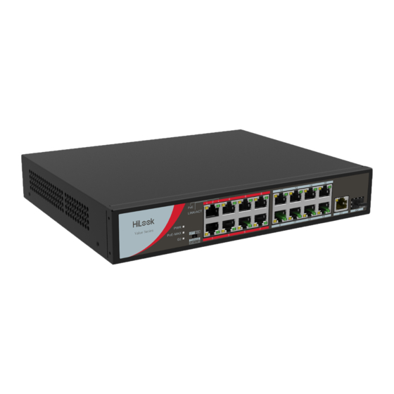
16/24-Port 100M Long-Range PoE Switch Quick Start Guide 1.3 Appearance 1.3.1 Front Panel Front panels of NS-0318P-130(B) and NS-0326P-230(B) are shown as below. Front Panel of NS-0318P-130(B) Figure 1-1 NS-0318P-130(B) Front Panel Front Panel of NS-0326P-230(B) Figure 1-2 NS-0326P-230(B) Front Panel Indicator Indicators are used to monitor the status of switches. - Page 7 16/24-Port 100M Long-Range PoE Switch Quick Start Guide indicator Flashing The 1000M RJ45 port is transmitting data. Unlit No 1000M RJ45 port connected or connection is abnormal. G2 port Solid on The SFP fiber optical port is connected. indicator Flashing The SFP fiber optical port is transmitting data.
-
Page 8: Grounding Terminal
16/24-Port 100M Long-Range PoE Switch Quick Start Guide Rear Panel of NS-0318P-130(B) and NS-0326P-230(B) Figure 1-3 NS-0318P-130(B) and NS-0326P-230(B) Rear Panel Grounding Terminal The grounding terminal is used to connect to the ground cable to protect the switch from lightning. For details about grounding, see section Grounding. -
Page 9: Chapter 2 Installation
16/24-Port 100M Long-Range PoE Switch Quick Start Guide Chapter 2 Installation 2.1 Preventive and Cautionary Tips Before installation, put on anti-static gloves. During the installation, power off your switch. Use the attached power adapter or power cord to connect the switch to power supply. ... -
Page 10: Lightning Protection
16/24-Port 100M Long-Range PoE Switch Quick Start Guide 2.2.3 Lightning Protection In thunderstorm weather, a sudden strong current may damage the switch. To protect your switch from lightning strike or strong current, please: Make sure the switch, rack, installation desktop, and power socket on the wall all are well-grounded. -
Page 11: With Grounding Bar
16/24-Port 100M Long-Range PoE Switch Quick Start Guide Figure 2-2 Fix Switch to Rack Do not place any heavy object on the switch in case of any incident. Make sure sound cooling and ventilation. 2.4 Grounding Purpose: Grounding is used to quickly release overvoltage and overcurrent induced by lightening for switch, and to protect personal safety. -
Page 12: Without Grounding Bar
16/24-Port 100M Long-Range PoE Switch Quick Start Guide Figure 2-3 Grounding with Grounding Bar Connect the grounding cable to the grounding system in the equipment room. Do not connect it to a fire main or lightning rod. 2.4.2 Without Grounding Bar If there is no grounding bar but earth is nearby and the grounding body is allowed to be buried, follow the steps below. - Page 13 16/24-Port 100M Long-Range PoE Switch Quick Start Guide Figure 2-4 Grounding with Angle Steel If it is not proper to bury the grounding body, an AC-powered Ethernet switch can be grounded by using the PE (Protective Earth) wire of the AC power supply. The prerequisite is that the power cord of the switch should adopt 3-pin cable with protective earth wire, and the AC power supply protective earth wire has been well grounded on the side of distribution room or AC power supply transformer.
-
Page 14: Connecting Rj45 Port
16/24-Port 100M Long-Range PoE Switch Quick Start Guide Chapter 3 Physical Connection 3.1 Connecting RJ45 Port Use a network cable to connect your switch to the RJ45 port of an opposite end device. The RJ45 port can connect with network camera, IP camera, NVR, switch, etc. Figure 3-1 RJ45 Port Connection 3.2 Connecting Gigabit Fiber Optical Port This section uses dual-fiber SFP optical module as an example. -
Page 15: Checking The Cabling
16/24-Port 100M Long-Range PoE Switch Quick Start Guide Step 3 After powering on your switch, check the status of Link/Act indicator. If the indicator is lit, the link is connected. If the indicator is unlit, the link is disconnected. Check the line, and make sure opposite devices have been started. - Page 16 UD15464B...
Need help?
Do you have a question about the NS-0318P Series and is the answer not in the manual?
Questions and answers