Table of Contents
Advertisement
Quick Links
Advertisement
Table of Contents

Related Manuals for HIKVISION DS-3T3512P


Summary of Contents for HIKVISION DS-3T3512P
- Page 1 DS-3T3512P Gigabit PoE Switch User Manual...
-
Page 2: Legal Information
WITHOUT LIMITATION, MERCHANTABILITY, SATISFACTORY QUALITY, OR FITNESS FOR A PARTICULAR PURPOSE. THE USE OF THE PRODUCT BY YOU IS AT YOUR OWN RISK. IN NO EVENT WILL HIKVISION BE LIABLE TO YOU FOR ANY SPECIAL, CONSEQUENTIAL, INCIDENTAL, OR INDIRECT DAMAGES, INCLUDING,... -
Page 3: Regulatory Information
Regulatory Information FCC Information Please take attention that changes or modification not expressly approved by the party responsible for compliance could void the user's authority to operate the equipment. FCC compliance: This equipment has been tested and found to comply with the limits for a Class A digital device, pursuant to part 15 of the FCC Rules. -
Page 4: Applicable Models
Preface Applicable Models This manual is applicable to DS-3T35XXP series switches. Symbol Conventions The symbols that may be found in this document are defined as follows. Symbol Description Indicates a hazardous situation which, if not avoided, will or could result Danger in death or serious injury. -
Page 5: Chapter 1 Introduction
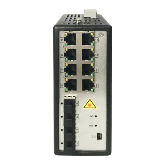
Chapter 1 Introduction 1.1 Product Introduction DS-3T3512P series switches (hereinafter referred to as "the device") are layer 3 Industrial PoE switches, providing advanced PoE power supply technology on the basis of high-performance access. The switches support client management, network topology management, link aggregation, port management and so on. - Page 6 Switch × 1 Console line × 1 Quick Start Guide × 1 Packing list × 1 1.3 Appearance Different models of devices may have different appearances. The following pictures are only for illustration. Front Panel Figure 1-1 DS-3T3512P Front Panel...
- Page 7 Rear Panel Figure 1-2 DS-3T3512P Rear Panel Port/Indicator Description Indicator/Port Description ● Solid: The switch is powered on normally. PWR Indicator ● Unlit: No power supply connected or power supply is abnormal. ● Solid: The port is connected. SFP LINK/ACT Indicator ●...
-
Page 8: Chapter 2 Installation
Similar to other electronic products, the semiconductor chip easily gets damaged if you power on and off abruptly and frequently. To restart up the switch of DS-3T3512P, you have to open the power on-off three or five seconds after the power is cut off. - Page 9 Pull out the AC power socket and close the direct-current power before operating on the chassis or working beside the power source. The final configuration of products must comply with relative national laws and regulations. 2.2.3 Safety Principles for Live Working When you work under electricity, following the following principles: ...
-
Page 10: Requirements For Common Locations
2.2.4 Electrostatic Discharge Prevention Electrostatic discharge may damage devices and circuits. Improper treatment may cause the switch to malfunction completely or discontinuously. Move or locate the devices according to the measures of electrostatic discharge prevention, ensuring the chassis connects the ground. Another measure is to wear the static-proof hand ring. If there is no hand ring, use the metal clip with the metal cable to clip the unpainted metal part of the chassis. -
Page 11: Chapter 3 Grounding
If the power supply system does not have good grounding, or the input power disturbs too much and excessive pulses exist, the error code rate of communication devices increases and even the hardware system will be damaged. Chapter 3 Grounding 3.1 Connecting the Grounding Cable Grounding is used to quickly release overvoltage and overcurrent induced by lightening for switch, and to protect personal safety. - Page 12 3.1.2 Without Grounding Bar If there is no grounding bar but the earth is nearby and the grounding body is allowed to be buried, follow the steps below. Steps 1. Bury an angle steel or steel pipe (≥ 0.5 m) into the mud land. 2.
- Page 13 3.2 Connecting RJ45 Port Use a network cable to connect the device to the RJ45 port of a peer device such as network camera, NVR, switch, etc. Figure 3-3 RJ45 Port Connection 3.3 Connecting SFP Optical Module Connecting SFP optical module is supported when the device has a fiber optic port or a combo. When connected to a network cable, the combo is a RJ45 port.
-
Page 14: Chapter 4 Powering On The Device
Before You Start The computer and the device are on the same network segment. Steps Note Take DS-3T3512P as an example. All figures in this manual are for illustration purpose only. 1. Enter the default IP https://192.168.1.64 in the browser address bar. - Page 15 Figure 5-2 Activation Note You are recommended to use the newest version of the following browsers: IE 10+, Edge, and Chrome 31+. 2. Configure the password and confirm it. 3. Click OK. Go to the login page. Figure 5-3 Login 4.
Need help?
Do you have a question about the DS-3T3512P and is the answer not in the manual?
Questions and answers