CF MOTO 600 Owner's Manual
Hide thumbs
Also See for 600:
- Owner's manual (205 pages) ,
- Owner's manual (195 pages) ,
- Owner's manual (378 pages)
Advertisement
Advertisement
Table of Contents

Related Manuals for CF MOTO 600


Summary of Contents for CF MOTO 600
- Page 1 All manuals and user guides at all-guides.com 600(CF600-5)
- Page 2 All manuals and user guides at all-guides.com Read, understand, and follow all of the instructions and safety precautions in this manual and on all product labels. Failure to follow the safety precautions could result in serious injury or death. The engine exhaust gas from this product contains CO, which is deadly gas and could cause headaches, giddy, or lose consciousness, even death.
- Page 3 All manuals and user guides at all-guides.com INTRODUCTION Thank you for purchasing a CFMOTO vehicle, and welcome to join our worldwide family of CFMOTO owners. We proudly produce an exciting line of utility and recreational products. All terrain vehicle (ATV) Utility vehicle (patrol, forest protecting and hunting) Motorcycles and scooters CFMOTO, a company which is specialized in production of liquid‐cooled engine, is the top‐level...
-
Page 4: Table Of Contents
All manuals and user guides at all-guides.com TABLE OF CONTENTS VIN No Location and record Operator Safety Warning and Specification Labels Features and Controls Operation Guide for Safe Use Maintenance & Adjustments Troubleshooting Cleaning & Storage Specifications Wiring diagram... - Page 5 All manuals and user guides at all-guides.com VEHICLE IDENTIFICATION NUMBER Record your vehicle's identification number and engine serial number in the spaces provided, remove the extra "ignition” key and store it in a safe place for duplicating spare key if keys are lost, otherwise ignition key can only be replaced.
-
Page 6: Operator Safety
All manuals and user guides at all-guides.com OPERATOR SAFETY Failure to heed the warnings contained in this manual can result in serious injury or death. An UTV is not a toy and can be hazardous to operate. This vehicle handles differently from other vehicles, such as motorcycles and cars. - Page 7 All manuals and user guides at all-guides.com OPERATOR SAFETY SAFETY TRAINING When you purchased your new UTV, your dealer offered a hands‐on safety‐training course that covers all aspects of vehicle safety. You were also provided with printed materials that explain safe operating procedures.
- Page 8 All manuals and user guides at all-guides.com OPERATOR SAFETY CAUTION A caution indicates a situation that may result in damage to the vehicle. NOTE A note will alert you to important information or instructions. Serious injury or death can result if you don't follow these instructions and procedures, which are outlined in further detail within your owner's manual.
- Page 9 All manuals and user guides at all-guides.com OPERATOR SAFETY Never operate at excessive speeds. Travel at speeds appropriate for the terrain, visibility and operating conditions, and your experience. Always keep hands and feet inside vehicle. Always inspect your UTV before each use to make sure it is in safe operating condition. Always follow the inspection and maintenance procedures and schedules outlined in your owner’s manual.
- Page 10 All manuals and user guides at all-guides.com OPERATOR SAFETY Always follow proper procedures for going downhill and for braking on hills. Check the terrain carefully before you start down a hill. Shift your weight backward. Never go down a hill at high speed. Avoid going down a hill at an angle, which would cause the vehicle to lean sharply to one side.
- Page 11 All manuals and user guides at all-guides.com OPERATOR SAFETY Avoid operating the UTV through deep or fast‐flowing water. If it is unavoidable, travel slowly, balance your weight carefully, avoid sudden movements, and maintain a slow and steady forward motion. Do not make sudden turns or stops, and do not make sudden throttle changes. Wet brakes may have reduced stopping ability.
- Page 12 All manuals and user guides at all-guides.com OPERATOR SAFETY This vehicle handles differently than cars, trucks or other off‐road vehicles. Turning improperly can result in an overturn. Avoid sharp turns. Never turn while applying heavy throttle. Never make abrupt steering maneuvers. Operate at speeds appropriate for your skills, the conditions, and terrain.
- Page 13 All manuals and user guides at all-guides.com OPERATOR SAFETY EQUIPMENT MODIFICATIONS We are concerned with the safety of our customers and for the public. Therefore, we strongly recommend that consumers do not install on an UTV any equipment that may increase the speed or power of the vehicle, or make any other modifications to the vehicle for these purposes.
- Page 14 All manuals and user guides at all-guides.com OPERATOR SAFETY POTENTIAL HAZARD Operating this vehicle without proper instruction. WHAT CAN HAPPEN Loss of control and accident resulting in serious injury or death. HOW TO AVOID THE HAZARD The risk of an accident is greatly increased if the operator does not know how to operate the vehicle properly in different situations and on different types of terrain.
- Page 15 All manuals and user guides at all-guides.com OPERATOR SAFETY POTENTIAL HAZARD Riding in this vehicle without wearing the seat belt. WHAT CAN HAPPEN Serious injury or death in the event of an accident or sudden stop. HOW TO AVOID THE HAZARD Always make sure the seat belts are secured for both the operator and passenger before riding.
- Page 16 All manuals and user guides at all-guides.com OPERATOR SAFETY POTENTIAL HAZARD Riding this vehicle without wearing an approved helmet and eye protection. WHAT CAN HAPPEN Head injury, eye injury or death in the event of an accident. HOW TO AVOID THE HAZARD Operator and passenger: Always wear an approved helmet that fits properly.
- Page 17 All manuals and user guides at all-guides.com OPERATOR SAFETY POTENTIAL HAZARD Removing hands from the steering wheel or handholds or removing feet from the floor while riding. WHAT CAN HAPPEN Loss of control and accident resulting in serious injury or death. HOW TO AVOID THE HAZARD The operator should always keep both hands on the steering wheel during operation.
- Page 18 All manuals and user guides at all-guides.com OPERATOR SAFETY POTENTIAL HAZARD Using accessories not approved by CFMOTO for use on this vehicle. WHAT CAN HAPPEN Loss of control, accident, or overturn resulting in serious injury or death. HOW TO AVOID THE HAZARD Never operate with accessories not approved by CFMOTO for use on this vehicle.
- Page 19 All manuals and user guides at all-guides.com OPERATOR SAFETY POTENTIAL HAZARD Operating this vehicle on public streets, roads or highways. WHAT CAN HAPPEN Collision with another vehicle. HOW TO AVOID THE HAZARD Never operate this vehicle on any public street, road, or highway, including dirt or gravel.
- Page 20 All manuals and user guides at all-guides.com OPERATOR SAFETY POTENTIAL HAZARD Skidding or sliding. WHAT CAN HAPPEN Loss of control, accident, or overturn resulting in serious injury or death. HOW TO AVOID THE HAZARD Always follow proper procedures for operating on slippery surfaces as described in the owner's manual.
- Page 21 All manuals and user guides at all-guides.com OPERATOR SAFETY POTENTIAL HAZARD Improperly operating in reverse. WHAT CAN HAPPEN Collision with an obstacle or person, resulting in severe injury or death. HOW TO AVOID THE HAZARD Always follow proper procedures for operating in reverse as described in the owner's manual.
- Page 22 All manuals and user guides at all-guides.com OPERATOR SAFETY Never exceed the stated load capacity for this vehicle. Cargo should be properly distributed and securely attached. Reduce speed when carrying cargo or pulling a trailer. Allow a greater distance for braking. POTENTIAL HAZARD Operating this vehicle with improper tires or with improper or uneven tire pressure.
- Page 23 All manuals and user guides at all-guides.com OPERATOR SAFETY POTENTIAL HAZARD Climbing hills improperly. WHAT CAN HAPPEN Loss of control or overturn resulting in serious injury or death HOW TO AVOID THE HAZARD Always follow proper procedures for climbing hills as described in the owner's manual.
- Page 24 All manuals and user guides at all-guides.com OPERATOR SAFETY POTENTIAL HAZARD Traveling downhill improperly. WHAT CAN HAPPEN Loss of control or overturn resulting in serious injury or death. HOW TO AVOID THE HAZARD Always follow proper procedures for traveling down hills as described in the owner's manual.
- Page 25 All manuals and user guides at all-guides.com OPERATOR SAFETY POTENTIAL HAZARD Stalling, rolling backwards while climbing a hill. WHAT CAN HAPPEN Loss of control or overturn resulting in serious injury or death. HOW TO AVOID THE HAZARD Maintain a steady speed when climbing a hill. If you lose all forward speed: Apply the brakes gradually until the vehicle is fully stopped.
- Page 26 All manuals and user guides at all-guides.com OPERATOR SAFETY POTENTIAL HAZARD Operating this vehicle at excessive speeds. WHAT CAN HAPPEN Loss of control and accident resulting in serious injury or death. HOW TO AVOID THE HAZARD Operate at speeds appropriate for your skills, the conditions, and the terrain.
- Page 27 All manuals and user guides at all-guides.com OPERATOR SAFETY POTENTIAL HAZARD Operating on frozen bodies of water. WHAT CAN HAPPEN Severe injury or death if the vehicle and/or riders fall through the ice. HOW TO AVOID THE HAZARD Never operate this vehicle on a frozen body of water. POTENTIAL HAZARD Failure to use extra caution when operating this vehicle on unfamiliar terrain.
- Page 28 All manuals and user guides at all-guides.com OPERATOR SAFETY POTENTIAL HAZARD Carrying a passenger in the cargo box. WHAT CAN HAPPEN Serious injury or death due to a fall from the vehicle or contact with moving components. HOW TO AVOID THE HAZARD Never allow a passenger to ride in the cargo box.
- Page 29 All manuals and user guides at all-guides.com OPERATOR SAFETY Operating a damaged vehicle can result in an accident with serious injury or death. After any overturn or accident, have a qualified service dealer inspect the entire vehicle for possible damage, including (but not limited to) brakes, throttle and steering systems. Exhaust system components are very hot during and after use of the vehicle.
- Page 30 All manuals and user guides at all-guides.com OPERATOR SAFETY Gasoline is highly flammable and is explosive under certain conditions. Always exercise extreme caution whenever handling gasoline. Always stop the engine when refueling. Always refuel outdoors or in a well‐ventilated area. Remove flammable material containers from the box before filling.
-
Page 31: Warning And Specification Labels
All manuals and user guides at all-guides.com LABELS LOCATION OF WARNING AND SPECIFICATION LABELS Read and understand all of the labels on your vehicle. They contain important information for safe and proper operation of your vehicle. Never remove any labels from your vehicle. If a label becomes difficult to read or comes off, a replacement labels available from your dealer. - Page 32 All manuals and user guides at all-guides.com LABELS -31-...
- Page 33 All manuals and user guides at all-guides.com LABELS when -32-...
- Page 34 All manuals and user guides at all-guides.com LABELS -33-...
- Page 35 All manuals and user guides at all-guides.com LABELS -34-...
- Page 36 All manuals and user guides at all-guides.com LABELS -35-...
-
Page 37: Features And Controls
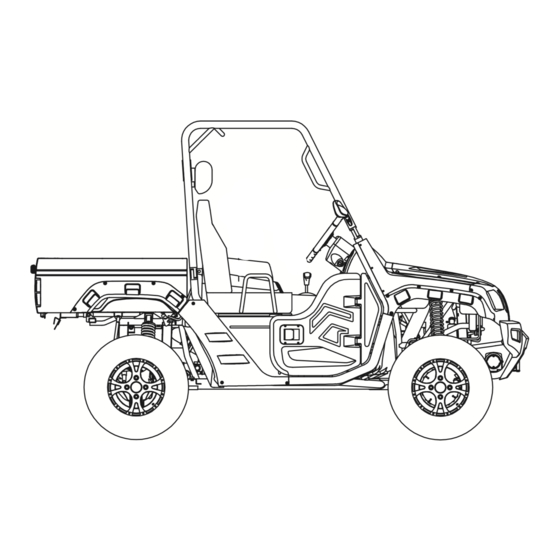
All manuals and user guides at all-guides.com FEATURES AND CONTROLS -36-... - Page 38 All manuals and user guides at all-guides.com FEATURES AND CONTROLS The vehicle you have purchased may differ slightly from those shown in the figures of this manual. -37-...
- Page 39 All manuals and user guides at all-guides.com FEATURES AND CONTROLS Functions of the respective switch positions are as follows: ON: All electrical circuits are supplied with power, and the headlights and taillights come on when the light switch is on. OFF: All electrical circuits are switched off.
- Page 40 All manuals and user guides at all-guides.com FEATURES AND CONTROLS INDICATOR AND WARNING LAMPS COOLANT WARNING LIGHT When the temperature indicator is in the white are of the side C, it means that the temperature is normal. If the indicator is in the Red area this means the engine temperature is high. If the indicator is in the Red stop the engine and let the engine coolant cool down.
- Page 41 All manuals and user guides at all-guides.com FEATURES AND CONTROLS LOW RANGE INDICATOR LIGHT “L” This indicator will illuminate when the drive select lever is in the “L” position. HIGH RANGE INDICATOR LIGHT “H” This indicator will illuminate when the drive select lever is in the “H” position. NEUTRAL INDICATOR LIGHT "N"...
- Page 42 All manuals and user guides at all-guides.com FEATURES AND CONTROLS The Multi‐function meter is equipped with the following: Left Turn Signal Speedometer (Show vehicle speed) Right turn Signal Fuel Level Meter Light Symbol Odometer ① ② ③ ⑤ Left Turn Signal Speedometer Right Turn Signal Fuel meter...
- Page 43 All manuals and user guides at all-guides.com FEATURES AND CONTROLS FUEL METER Indicates the remaining amount of the gasoline in the fuel tank. (F) Indicates the fuel tank is full 7.1 g (27L). When the indicator reaches the first point of red mark, fuel should be refilled as soon as possible.
- Page 44 All manuals and user guides at all-guides.com FEATURES AND CONTROLS LIGHT SWITCHES ON/ Set the switch to to turn on the running lights. Set the switch to and set the switch to to turn on the Low beam and taillights. Set the switch to and set the switch to to turn...
- Page 45 All manuals and user guides at all-guides.com FEATURES AND CONTROLS ON‐COMMAND FOUR‐WHEEL‐DRIVE AND DIFFERENTIAL GEAR LOCK SWITCHES 1. 2WD/4WD SWITCH 2. 4WD LOCK This UTV is equipped with an on‐command four‐wheel drive switch 2WD/4WD (1) and a front gear lock switch LOCK/4WD (2) Select the appropriate drive according to terrain and the conditions. Two‐wheel drive (2WD): Power is supplied to the rear wheels only.
- Page 46 All manuals and user guides at all-guides.com FEATURES AND CONTROLS ACCELERATOR PEDAL Press the accelerator pedal down to increase engine speed. Spring pressure returns the pedal to the rest position when released. Always check that the accelerator pedal returns normally before starting the engine.
- Page 47 All manuals and user guides at all-guides.com FEATURES AND CONTROLS PARKING BRAKE LEVER The parking brake lever is located at the right side of the Main switch. It will help keep the vehicle from moving while parked. To set the parking brake, pull the lever completely. To release the parking brake, turning the lever clockwise, spring pressure helps return the lever to the released position.
- Page 48 All manuals and user guides at all-guides.com FEATURES AND CONTROLS DRIVE SELECT LEVER The drive select lever is used to shift the vehicle into the low, high, neutral, and reverse positions. (Refer to page 71 for the drive select lever operation.) FUEL TANK CAP Remove the fuel tank cap by turning it counter clockwise.
- Page 49 All manuals and user guides at all-guides.com FEATURES AND CONTROLS DOORS To open a door, simply pull the latch outward. To close a door, push or pull the door inward until it is securely latched. Be sure the door is SECURELY LATCHED AFTER CLOSING IT. 1.
- Page 50 All manuals and user guides at all-guides.com FEATURES AND CONTROLS SEATS To open the seat, turn the seat lock key clockwise, and turn the seat. To adjust the forward or backward, raise the seat lock lever, and move forward or backwards. A loose seat could cause the operator or passenger to fall out of the vehicle.
- Page 51 All manuals and user guides at all-guides.com FEATURES AND CONTROLS SEAT BELTS This vehicle is equipped with three‐point seat belts for both the operator and the passenger. Always wear the seat belts properly while riding in the vehicle. See page 84 for more information. GLOVE COMPARTMENT NOTICE To protect from damage, do not put metal products, like...
- Page 52 All manuals and user guides at all-guides.com FEATURES AND CONTROLS CARGO BED Maximum load limit is 150 lbs (330kg). For further loading information see (Page 76) REAR TAILGATE TO OPEN Unhook the latches, and then lower the tailgate. TO CLOSE Place the tailgate in the original position, and then hook the latches.
- Page 53 All manuals and user guides at all-guides.com FEATURES AND CONTROLS LIFTING AND LOWERING THE CARGO BED TO LIFT Push the cargo bed, release lever at the left or right side of the seat back, and then slowly lift up the cargo bed until it stops. TO LOWER With hands and fingers clear of pinch points, lower the cargo bed slowly to its original position and be sure it is locked into place.
- Page 54 All manuals and user guides at all-guides.com FEATURES AND CONTROLS FRONT AND REAR SHOCK ABSORBER ADJUSTMENT The spring preload can be adjusted to suit the operating conditions. You can reduce preload for a softer ride, or increase preload if frequent bottoming occurs or when carrying loads. Always adjust the shock absorbers on the left and right sides to the same setting.
- Page 55 All manuals and user guides at all-guides.com FEATURES AND CONTROLS Adjusting the shocks requires a special wrench which can be obtained from a CFMOTO dealer. Position (A) Minimum Soft Position (B) Standard Position (E) Maximum Hard TRAILER HITCH Your vehicle may be equipped with a trailer hitch receiver.
- Page 56 All manuals and user guides at all-guides.com FEATURES AND CONTROLS AUXILIARY DC JACK The auxiliary DC jack is located at the right side of the front panel. The auxiliary DC jack can be used for suitable work lights, radios, etc. The auxiliary DC jack should only be used when the engine is running.
- Page 57 All manuals and user guides at all-guides.com PRE‐RIDE INSPECTIONS PRE‐RIDE INSPECTION If a proper inspection is not done before each use, severe injury, or death could result. Always inspect the vehicle before each use to ensure it is in proper operating condition. PRE‐RIDE CHECKLIST ITEM REMARKS...
- Page 58 All manuals and user guides at all-guides.com PRE‐RIDE INSPECTIONS PRE‐RIDE CHECKLIST SEE PAGE ITEM REMARKS Frame nuts, bolts, Inspect, ensure fastener tightness fasteners Fuel and oil Ensure proper levels Coolant level Ensure proper levels Coolant hoses Inspect for leaks Throttle Ensure proper operation Gear shifting Ensure proper operation...
- Page 59 All manuals and user guides at all-guides.com PRE‐RIDE INSPECTIONS FRONT AND REAR BRAKES BRAKE PEDAL Check for correct brake pedal free play.If the brake pedal free play is incorrect, have your dealer adjust it.(See page 136.) Check the brake pedal operation.It should move smoothly and should be firm feeling when the brakes are applied.If the pedal feels soft have the vehicle inspected by you dealer.
- Page 60 All manuals and user guides at all-guides.com PRE‐RIDE INSPECTIONS FUEL Make sure there is sufficient gasoline in the tank. 1. Gasoline and gasoline vapors are extremely flammable. To avoid fires and explosions and to reduce the risk of injury when refueling, follow these instructions. 2.
- Page 61 All manuals and user guides at all-guides.com PRE‐RIDE INSPECTIONS Your engine has been designed to use regular unleaded gasoline with a pump octane number 93 or higher. If knocking or pinging occurs, use a different brand of gasoline or premium unleaded fuel. GASOHOL There are two types of gasohol: gasohol containing ethanol and that containing methanol.
- Page 62 All manuals and user guides at all-guides.com PRE‐RIDE INSPECTIONS ENGINE OIL Make sure the engine oil is at the specified level, add oil if necessary (see page 110) NOTICE In order to prevent clutch slippage (engine oil also lubricates the clutch), do not use oils which are specified for diesel engine and mark with the label “CD”...
- Page 63 All manuals and user guides at all-guides.com PRE‐RIDE INSPECTIONS COOLANT Check the coolant level in the coolant reservoir when the engine is cold (the level may change with the engine temperature. The coolant level is satisfactory if it is between the minimum and maximum level marks on the coolant reservoir.
- Page 64 All manuals and user guides at all-guides.com PRE‐RIDE INSPECTIONS ACCELERATOR PEDAL Check to see that the accelerator pedal operates freely. It must operate smoothly and return to the idle position fully when released. Have your dealer repair as necessary for proper operation. SEAT BELTS Make sure the seat belts are not frayed or torn, stretched or damaged.
- Page 65 All manuals and user guides at all-guides.com PRE‐RIDE INSPECTIONS LIGHTS Check the headlights and tail/brake lights to make sure they are in working condition. Repair as necessary for proper operation. SWITCHES Check the operation of all switches. Have your dealer repair as necessary for proper operation. CONTROL CABLES When riding in cold weather, always make sure all control cables work smoothly before you begin riding.
- Page 66 All manuals and user guides at all-guides.com PRE‐RIDE INSPECTIONS Set tire pressures to the following specifications: Minimum Recommended pressure Minimum Front 70 kPa (0.80 77 kPa (0.77 63 kPa (0.63 kgf/cm•, 11 psi) kgf/cm•, 10psi) kgf/cm•, 9 psi) 98 kPa (0.98 77 kPa(0.77 84 kPa (0.84 Rear...
- Page 67 All manuals and user guides at all-guides.com PRE‐RIDE INSPECTIONS TIRE WEAR LIMIT When the tire groove decreases to 3 mm (0.12 in) due to wear, replace the tire. -66-...
-
Page 68: Operation
All manuals and user guides at all-guides.com OPERATION Read the Owner's Manual carefully to become familiar with all controls. If there is a control or function you do not understand, ask your dealer. Failure to familiarize yourself with the controls can lead to loss of control, which could result in an accident or injury. - Page 69 All manuals and user guides at all-guides.com OPERATION Each full‐throttle acceleration sequence should be followed with a substantial rest period for the engine, by cruising at lower rpm so the engine can cool down. If any abnormality is onticed during this period, consult your dealer.
- Page 70 All manuals and user guides at all-guides.com OPERATION STARTING A COLD ENGINE 1. Apply the brake pedal. 2. Shift the drive select lever into the neutral position. When the drive select lever is in the neutral position, the neutral indicator light should come on. If the neutral indicator light does not come on, ask your dealer to inspect the electric circuit.
- Page 71 All manuals and user guides at all-guides.com OPERATION If the engine fails to start, release the key, and then try starting it again. Wait a few seconds before the next attempt. Each attempt should be as short as possible, to preserve battery energy. NOTICE: Do not crank the engine more than 5 seconds on each attempt, or starter damage could occur.
- Page 72 All manuals and user guides at all-guides.com OPERATION With the vehicle still in neutral, continue to warm up the engine until it idles smoothly before riding. Failure to do so may result in poor performance and premature engine wear and V‐belt wear.
- Page 73 All manuals and user guides at all-guides.com OPERATION SHIFTING: NEUTRAL TO HIGH AND HIGH TO LOW 1. Stop the vehicle. Take your foot off the accelerator pedal. 2. Apply the brake pedal, then shift by moving the drive select lever along the shift guide. 3.
- Page 74 All manuals and user guides at all-guides.com OPERATION When in reverse, the reverse indicator light should be on. Due to the synchronizing mechanism in the engine, the light may not come on until the vehicle starts moving. If the light does not come on, ask your dealer to inspect the reverse indicator light electrical circuit. 4.
- Page 75 All manuals and user guides at all-guides.com OPERATION ON‐COMMAND FOUR‐WHEEL‐DRIVE SWITCH AND DIFFERENTIAL GEAR LOCK SWITCH You may notice that the vehicle handles differently in 2WD, 4WD, and 4WD‐LOCK ("DIFF. LOCK"). For example, you should expect that the vehicle would require more effort to turn in 4WD‐LOCK ("DIFF.
- Page 76 All manuals and user guides at all-guides.com OPERATION ON COMMAND DIFFERENTIAL GEAR LOCK SWITCH "4WD"/'LOCK" To lock the differential gear in 4WD, stop the vehicle, make sure the On‐Command four wheel-drive switch is set to "4WD", move the differential gear lock lever to position (b), and then set the switch to "LOCK”∙.When the differential gear is locked, the differential gear lock indicator light ("DIFF.
- Page 77 All manuals and user guides at all-guides.com OPERATION PARKING When parking, stop the engine and shift the drive select lever into the neutral position. Apply the parking brake to help prevent the vehicle from rolling. See page 95 for more information on praking and parking on a slope.
- Page 78 All manuals and user guides at all-guides.com OPERATION Use the hooks equipped on the cargo bed to tie down loads. You can measure tongue weight with a bath‐room scale. Put the tongue of the loaded trailer on the scale with the tongue at hitch height. Adjust the load in the trailer, if necessary, to reduce the weight on hitch.
- Page 79 All manuals and user guides at all-guides.com OPERATION Carrying loads or towing a trailer can increase the risk of loss of control, an over turn, or other accident. To reduce the risk of an accident: Reduce speed, operate in low gear only, and allow more room to stop. A heavier vehicle takes longer to stop.
-
Page 80: Guide For Safe Use
All manuals and user guides at all-guides.com GUIDE FOR SAFE USE As a UTV owner you are responsible for the safe and proper operation of this vehicle. Read this chapter and review the safely instructions in this manual, before operating the vehicle. Use these chapters and the labels on the vehicle to instruct new operators and passengers. - Page 81 All manuals and user guides at all-guides.com GUIDE FOR SAFE USE Doing things with a UTV that some people do for thrills, in other vehicles, (such as sideways sliding, skidding, fishtailing, or donuts) have led to side rollovers. These rollovers can result in crushed limbs and other serious injuries or death to drivers or passengers.
- Page 82 All manuals and user guides at all-guides.com GUIDE FOR SAFE USE DRIVER REQUIREMENTS This vehicle is intended for use only by an operator 16 or older with a valid motor vehicle license. The driver must be able to place both feet flat on the floorboard while seated upright with his/her back against the seat back.
- Page 83 All manuals and user guides at all-guides.com GUIDE FOR SAFE USE PASSENGER REQUIREMENTS Occupant protection system This vehicle is designed for the operator and one passenger, carrying more than one passenger can be dangerous and could lead to injury or death. As the operator, you are responsible for your passenger.
- Page 84 All manuals and user guides at all-guides.com GUIDE FOR SAFE USE Do not make changes to the occupant protection system. If you install aftermarket products or have your vehicle modified, you may put yourself and others at greater risk of serious injury or death.
- Page 85 All manuals and user guides at all-guides.com GUIDE FOR SAFE USE PROTECTIVE STRUCTURE The vehicle cage/frame provides a protective structure that helps limit intrusions by branches or other objects and may reduce your risk of injury in accidents. The protective structure will not protect occupants in all rollovers or accidents.
- Page 86 All manuals and user guides at all-guides.com GUIDE FOR SAFE USE An unbelted occupant may strike the interior of the vehicle, the protective structure, or other objects in an accident or during operation. You may also fall completely out or be partially ejected from the vehicle, which may lead to being crushed between the ground and the vehicle.
- Page 87 All manuals and user guides at all-guides.com GUIDE FOR SAFE USE 2. If the latch plate is not positioned in the correct location along the seat belt, squeeze the latch plate ends together along its long edges in order to more easily adjust its location up or down along the length of the belt.
- Page 88 All manuals and user guides at all-guides.com GUIDE FOR SAFE USE DOORS The doors are designed to reduce the likelihood that you will stick your leg out while the vehicle is moving or to keep the vehicle from tipping over or for any other reason in a rollover.
- Page 89 All manuals and user guides at all-guides.com GUIDE FOR SAFE USE SEAT AND HIP RESTRAINTS The seat and hip restraints are designed to help keep you in the vehicle. Do not hold onto hip restraint bar when the vehicle is moving. Your hand or arm may be struck by objects or crushed against outside objects or the ground during a rollover.
- Page 90 All manuals and user guides at all-guides.com GUIDE FOR SAFE USE STEERING WHEEL Keep both hands on the steering wheel. Do not hold the steering wheel with your thumbs inside the rim. Keep your palms on the outside of the steering wheel. Similar to other off road vehicles, if the UTV hits a deep rut or large obstacle, the steering wheel could briefly jerk in one direction or back and forth as the tires and vehicle respond to the obstacle.
- Page 91 All manuals and user guides at all-guides.com GUIDE FOR SAFE USE PROTECTIVE GEAR Both driver and passenger should wear the following to reduce risk of injury in an accident: Approved motorcycle helmet that fits properly Eye protection (goggles, helmet face shield, or protective eyewear Over the ankle boots, gloves, long‐sleeved shirt or jacket, and long pants.
- Page 92 All manuals and user guides at all-guides.com GUIDE FOR SAFE USE PRACTICE OPERATING YOUR NEW UTV You should become familiar with the performance characteristics of the vehicle in a large, flat area that is free of obstacles and other vehicles. Practice controlling the accelerator pedal, brakes, steering, and drive select lever.
- Page 93 All manuals and user guides at all-guides.com GUIDE FOR SAFE USE Become familiar with the way the vehicle feels in low and high ranges first in two‐wheel drive (2WD) and then in four‐wheel drive (4VVD) and four‐wheel drive with the differential locked (01‐...
- Page 94 All manuals and user guides at all-guides.com GUIDE FOR SAFE USE If you think or feel that the vehicle may tip or roll, keep your body completely inside the protective structure of the vehicle: Brace yourself by pressing your feet firmly on the floorboards and keep a firm grip on the steering wheel or handholds.
- Page 95 All manuals and user guides at all-guides.com GUIDE FOR SAFE USE Braking ability is affected by type of terrain. In most cases, gradual application of the brakes is more effective than abrupt braking, particularly on loose surfaces, such as gravel. Always allow for greater braking distance on rough, loose, or slippery surfaces.
- Page 96 All manuals and user guides at all-guides.com GUIDE FOR SAFE USE PARKING ON A FLAT AREA When parking on a flat area, stop the engine and shift the drive select lever into the neutral position. Apply the parking brake to help prevent the vehicle from rolling. PARKING ON A SLOPE The parking brake acts only on the rear wheels when in 2WD.
- Page 97 All manuals and user guides at all-guides.com GUIDE FOR SAFE USE OPERATION ON DIFFERENT SURFACES AND TERRAINS Go slowly and proceed with caution when operating on an unfamiliar surface or terrain. This vehicle may handle differently in certain types of terrains or on certain surfaces. You may come upon hidden rocks, bumps, or holes without enough time to react.
- Page 98 All manuals and user guides at all-guides.com GUIDE FOR SAFE USE If you think or feel the UTV may tip or roll over: Brace yourself by pressing your feet firmly on the floorboards and keep a firm grip on the steering wheel or handholds.
- Page 99 All manuals and user guides at all-guides.com GUIDE FOR SAFE USE UPHILL Do not attempt to climb hills until you have mastered basic maneuvers on flat ground. Drive straight up hills, and avoid crossing the side of a hill, which increases your risk of rollover. Practice first on gentle slopes before attempting sleeper hills.
- Page 100 All manuals and user guides at all-guides.com GUIDE FOR SAFE USE DOWNHILL Check the terrain carefully before going downhill. When possible, choose a path that lets you drive your vehicle straight downhill. Choose your path carefully and drive slowly enough to be able to react to obstacles that you encounter. For more traction and control, before going down steeper and/or rougher slopes, shift into low gear and select 4WD or 4WD Diff.
- Page 101 All manuals and user guides at all-guides.com GUIDE FOR SAFE USE ROUGH TERRAIN Operation over rough terrain should be done with caution. Look for and avoid obstacles that could cause damage to the vehicle or could lead to a rollover or accident. Do not drive in a way that will get the UTV airborne, as injury, loss of control, and damage to the vehicle could occur.
- Page 102 All manuals and user guides at all-guides.com GUIDE FOR SAFE USE Operating this vehicle through deep or fast flowing water can lead to loss of control or overturn. To reduce your risk of drowning or other injuries, use care when crossing through water.
- Page 103 All manuals and user guides at all-guides.com GUIDE FOR SAFE USE BRUSH OR WOODED AREAS When operating in areas with brush or trees, watch carefully on both sides and above the vehicle for obstacles such as branches that the vehicle might hit, causing an accident. Watch for brush that might enter the vehicle as you pass and strike you or the passenger.
-
Page 104: Maintenance & Adjustments
All manuals and user guides at all-guides.com MAINTENANCE AND ADJUSTMENTS Periodic inspection, adjustment, and lubrication will keep your vehicle in the safest and most efficient condition possible. Safely is an obligation of the vehicle owner/operator. The most important points of vehicle inspection, adjustment, and lubrication are explained on the following pages. - Page 105 All manuals and user guides at all-guides.com MAINTENANCE AND ADJUSTMENTS OWNER'S MANUAL AND TOOL KIT You are recommended to put this owner's manual in the glove compartment. Put the owner’s tool kit in the glove compartment. The service information included in this manual is intended to provide you, the owner, with the necessary information for completing your own preventive maintenance and minor repaits.
- Page 106 All manuals and user guides at all-guides.com MAINTENANCE AND ADJUSTMENTS Perform the instructions in the Pre‐Ride Inspection before driving refer to this section prior to each periodical maintenance. 1: Inspecting, cleaning, adjusting, lubricating, or replacing when necessary. C: Cleaning R: Replacing A: Adjusting L: Lubricating NOTE: (1) If the odometer reading reaches more than specified, perform the periodical maintenance.
- Page 107 All manuals and user guides at all-guides.com MAINTENANCE AND ADJUSTMENTS ODOMETER READING(kms)/Month (1) or which ever occurs first REMARKS (Pre-ride Inspection) (Pre-ride Inspection) Front & Rear Suspension (Pre-ride Inspection) (Pre-ride Inspection) (Pre-ride Inspection) (Pre-ride Inspection) R(every 2000km / 1200mi) (every 250km/150mi) (Pre-ride Inspection) (Pre-ride Inspection) R(inital:250km)
- Page 108 All manuals and user guides at all-guides.com MAINTENANCE AND ADJUSTMENTS ODOMETER READING(kms)/Month (1) or which ever occurs first REMARKS (every 500 km /300 mi) 1400rpm=/-100 (Pre-ride Inspection) (Pre-ride Inspection) Wheel and Frame Fasteners (Pre-ride Inspection) (Pre-ride Inspection) Lubricant Fluid levels (Pre-ride Inspection) Air filter(Primary) (Pre-ride Inspection)
- Page 109 All manuals and user guides at all-guides.com MAINTENANCE AND ADJUSTMENTS HOOD TO REMOVE Release the bolt 2, and remove the hood 1. TO INSTALL Reverse the removal procedure. NOTICE Make sure the hood is closed. Do not drive the vehicle with the hood open or removed.
- Page 110 All manuals and user guides at all-guides.com MAINTENANCE AND ADJUSTMENTS CONSOLE TO REMOVE 1. Remove the seats. (See page 49 for seat removal and installation procedures.) 2. Remove the drive select lever handle. 3. Pull the console upward. TO INSTALL 1.
- Page 111 All manuals and user guides at all-guides.com MAINTENANCE AND ADJUSTMENTS ENGINE OIL AND OIL FILTER CARTRIDGE Check engine oil level before each operation. In addition, change the oil and the oil filter cartridge at the intervals specified in the periodic maintenance and lubrication chart. To check the engine oil level 1.
- Page 112 All manuals and user guides at all-guides.com MAINTENANCE AND ADJUSTMENTS 8. Insert the dipstick into the oil filler hole, and then tighten the oil filler cap. 9. Reinstall the console. TO CHANGE THE ENGINE OIL (WITH OR WITHOUT OIL FILTER CARTRIDGE REPLACEMENT) 1.
- Page 113 All manuals and user guides at all-guides.com MAINTENANCE AND ADJUSTMENTS Skip steps 4 and 5 if the oil filter cartridge is not being replaced. 5. Remove the oil filter cartridge with an oil filter wrench. An oil filter wrench is available from your dealer.
- Page 114 All manuals and user guides at all-guides.com MAINTENANCE AND ADJUSTMENTS 8. Reinstall the engine oil drain, bolt, and then tighten it to the specified torque. Tightening torque: Engine oil drain bolt: 30 Nm (22 lbs ft) 9. Add the specified amount of recommended engine oil, and then reinstall the engine oil filler, cap and tighten it.
- Page 115 All manuals and user guides at all-guides.com MAINTENANCE AND ADJUSTMENTS NOTICE In order to prevent clutch slippage (since the engine oil also lubricates the clutch), do not mix any chemical additives with oil. Do not use oils with a diesel specification of "CD" or oils of a higher quality than specified. In addition, do not use oils labeled "ENERGY CONSERVING II"...
- Page 116 All manuals and user guides at all-guides.com MAINTENANCE AND ADJUSTMENTS FINAL GEAR OIL Checking the final gear oil level 1. Park the vehicle on a level surface. 2. Remove the oil filler bolt, and then check the oil level in the final gear case. The oil level shoud be at the brim of the filler hole.
- Page 117 All manuals and user guides at all-guides.com MAINTENANCE AND ADJUSTMENTS CHANGING THE FINAL GEAR OIL 1. Park the vehicle on a level surface. 2. Place a container under the final gear case to collect the used oil. 3. Remove the oil filler bolt and the drain bolt to drain the oil. 4.
- Page 118 All manuals and user guides at all-guides.com MAINTENANCE AND ADJUSTMENTS DIFFERENTIAL GEAR OIL 1. Checking the differential gear oil level 2. Park the vehicle on a level surface. 3. Remove the differential gear oil filler bolt and check the oil level. It should be up to the brim of the filler hole.
- Page 119 All manuals and user guides at all-guides.com MAINTENANCE AND ADJUSTMENTS Reinstall the differential gear oil drain bolt, and tighten it to the specified torque. Tightening (18 lb ft) torque: Differential gear oil drain bolt: 25Nm Fill the differential gear case with the recommended oil. NOTICE: Be sure no material enters the differential gear case.
- Page 120 All manuals and user guides at all-guides.com MAINTENANCE AND ADJUSTMENTS COOLANT The coolant level should be checked before each ride. CHECKING THE COOLANT LEVEL 1. Park the vehicle on a level surface. 2. Check the coolant level in the coolant reservoir when the engine is cold as the coolant level varies with engine temperature.
- Page 121 All manuals and user guides at all-guides.com MAINTENANCE AND ADJUSTMENTS CHANGING THE COOLANT The coolant should be changed by your dealer at the intervals specified in the periodic maintenance and lubrication chart. Adding water instead of coolant lowers the antifreeze content of the coolant. If water is used instead of coolant, have your dealer check the antifreeze content of the coolant as soon as possible.
- Page 122 All manuals and user guides at all-guides.com MAINTENANCE AND ADJUSTMENTS SPARK PLUG INSPECTION REMOVAL 1. Remove the console. (See page 109) 2. Remove the spark plug cap. 3. Use the spark plug wrench in the tool kit to remove the spark plug as shown. -121-...
- Page 123 All manuals and user guides at all-guides.com MAINTENANCE AND ADJUSTMENTS INSPECTION The spark plug is an important engine component and is easy to inspect. The condition of the spark plug can indicate the condition of the engine. The ideal color of the porcelain insulator around the center electrode is a medium‐to light tan for a vehicle that is being ridden normally.
- Page 124 All manuals and user guides at all-guides.com MAINTENANCE AND ADJUSTMENTS INSTALLATION 1. Measure the electrode gap with a wire thickness gauge and, if necessary, adjust the gap to specification. Spark plug gap: 0.~.9 mm (0.031‐0.035 in) 2. Clean the surface of the spark plug gasket and its mating surface, and then wipe off any grime from the spark plug threads.
- Page 125 All manuals and user guides at all-guides.com MAINTENANCE AND ADJUSTMENTS CLEANING THE ENGINE AIR FILTER ELEMENT 1. Remove the console. (See page 109) 2. There is a check hose at the bottom of the air filter case. If dust or water collects in this hose, empty the hose and clean the air filter element and air filter case.
- Page 126 All manuals and user guides at all-guides.com MAINTENANCE AND ADJUSTMENTS 4. Remove the air filter case, cover by unhooking the holders. 5. Remove the air filter element. ① ① ② -125-...
- Page 127 All manuals and user guides at all-guides.com MAINTENANCE AND ADJUSTMENTS 6.Remove the sponge material from its frame. Wash the sponge material gently but thoroughly in parts cleaning solvent. Using gasoline or other flammable solvents to clean the air filter element can cause a fire or explosion, which could lead to serious injury.
- Page 128 All manuals and user guides at all-guides.com MAINTENANCE AND ADJUSTMENTS 8. Wash the sponge material in warm soapy water to remove remaining solvent, and then rinse thoroughly with plain warm water. 9. Squeeze excess water out of the sponge material. NOTICE: Do not twist the sponge material when squeezing it.
- Page 129 All manuals and user guides at all-guides.com MAINTENANCE AND ADJUSTMENTS The air filter element should be cleaned every 20‐40 hours. It should be cleaned and lubricated more often if the vehicle is operated in extremely dusty areas. Each time air filter element, maintenance is performed, check the air inlet to the air filter case for obstructions.
- Page 130 All manuals and user guides at all-guides.com MAINTENANCE AND ADJUSTMENTS V‐BELT COOLING DUCT CHECK HOSE The V‐belt cooling duct check hose is located under the middle of the drive seat and the passenger seat. If dust or water collects in the V‐belt cooling duct check hose, remove the hose and clean it.
- Page 131 All manuals and user guides at all-guides.com MAINTENANCE AND ADJUSTMENTS CLEANING THE SPARK ARRESTER Hot exhaust system may cause burns. To avoid burns or fires, make sure that the engine is stopped and the exhaust system is cool before cleaning spark arrester. Do not start the engine while cleaning the exhaust system.
- Page 132 All manuals and user guides at all-guides.com MAINTENANCE AND ADJUSTMENTS IDLE ADJUSTMENT The throttle body is a vital part of the engine and requires very sophisticated adjustment. Most adjusting should be left to your dealer who has the professional knowledge and experience to do so.
- Page 133 All manuals and user guides at all-guides.com MAINTENANCE AND ADJUSTMENTS Specified idle speed: 1,200‐1,400 rpm. 6. Reinstall the console. 7. Reinstall the seats. VALVE CLEARANCE The correct valve clearance changes with use, resulting in improper fuel/air supply or engine noise. To prevent this, the valve clearance must be adjusted regularly. This adjustment however, should be left to a professional after service technician.
- Page 134 All manuals and user guides at all-guides.com MAINTENANCE AND ADJUSTMENTS BRAKES Replacement of brake components requires professional knowledge. Brake service should be performed by your dealer. Operating with improperly serviced or adjusted brakes could lead to a loss in braking ability and an accident.
- Page 135 All manuals and user guides at all-guides.com MAINTENANCE AND ADJUSTMENTS REAR BRAKE PAD CHECK Each brake pad is provided with wear indicator grooves, which allow you to check the brake pad wear without having to disassemble the brake. To check the brake pad wear, check the wear indicator grooves.
- Page 136 All manuals and user guides at all-guides.com MAINTENANCE AND ADJUSTMENTS CHECKING THE BRAKE FLUID Minimum level mark insufficient brake fluid may allow air to enter the brake system, possibly causing the brakes to become ineffective. Before riding, check that the brake fluid is above the minimum level mark and replenish, if necessary.
- Page 137 All manuals and user guides at all-guides.com MAINTENANCE AND ADJUSTMENTS Brake fluid may deteriorate painted surfaces or plastic parts. Always clean up spilled fluid immediately. Have your dealer inspect the brake system if the brake fluid level goes down. BRAKE FLUID REPLACEMENT Complete fluid replacement should be done only by trained after service personnel.
- Page 138 All manuals and user guides at all-guides.com MAINTENANCE AND ADJUSTMENTS PARKING BRAKE LEVER FREE PLAY ADJUSTMENT Periodically check the parking brake lever free play and adjust it if necessary. 1. Check the parking brake lever free play. The maximum free play is equal to one click of the parking brake lever.
- Page 139 All manuals and user guides at all-guides.com MAINTENANCE AND ADJUSTMENTS BRAKE LIGHT SWITCH ADJUSTMENT The brake light switch, which is activated by the brake pedal, is properly adjusted when the brake light comes on just before braking takes effect. If necessary, adjust the brake light switch as follows.
- Page 140 All manuals and user guides at all-guides.com MAINTENANCE AND ADJUSTMENTS CABLE INSPECTION AND LUBRICATION Damaged cables could restrict operation, which may cause an accident or injury. Inspect control cables frequently and replace damaged cables. Corrosion can result when the outer covering of control cables becomes damaged.
- Page 141 All manuals and user guides at all-guides.com MAINTENANCE AND ADJUSTMENTS REAR KNUCKLE UPPER AND LOWER PIVOT LUBRICATION Lubricate the knuckle upper and lower pivots with a grease gun. Recommended lubricant: Lithium‐based grease STEERING SHAFT LUBRICATION Lubricate the pivot points. Recommended lubricant: Lithium‐soap‐based grease -140-...
- Page 142 All manuals and user guides at all-guides.com MAINTENANCE AND ADJUSTMENTS WHEEL REMOVAL 1. Loosen the wheel nuts. 2. Elevate the vehicle and place a suitable stand under the frame. 3. Remove the nuts from the wheel. 4. Remove the wheel. TIRE REPLACEMENT Always use the same size and type of tires recommended in this owner's manual.
- Page 143 All manuals and user guides at all-guides.com MAINTENANCE AND ADJUSTMENTS WHEEL INSTALLATION 1. Install the wheel and the nuts. The arrow mark on the tire must point toward the rotating direction of the wheel. Tapered nuts are used for both the front and rear wheels. 2.
- Page 144 All manuals and user guides at all-guides.com MAINTENANCE AND ADJUSTMENTS WHEEL NUT TORQUE: Front: 55 Nm (40 lbs ft) Rear: 55 Nm (40 lbs ft) BATTERY This vehicle is equipped with a sealed‐type battery. Therefore it is not necessary to check the electrolyte or add distilled water in the battery. If the battery seems to have discharged, consult your dealer.
- Page 145 All manuals and user guides at all-guides.com MAINTENANCE AND ADJUSTMENTS Batteries may produce explosive gases. Ventilate when charging or using in a closed space. Keep batteries away from sparks, flames, cigarettes, or other sources of ignition. BATTERY MAINTENANCE 1. If the vehicle will not be used for a month or longer, remove the battery and store it in a cool, dark place.
- Page 146 All manuals and user guides at all-guides.com MAINTENANCE AND ADJUSTMENTS However, if the vehicle must be jump‐started, proceed as follows. 1. Turn the key to ∙OFF". 2. Remove the hood. (See page 108) 3. Remove the battery compartment cover. 4. Using a charged 12‐volt battery, connect the positive lead of the jumper cable to the positive positive terminal of the battery in the vehicle and the other end of the positive lead to terminal of the charged battery.
- Page 147 All manuals and user guides at all-guides.com MAINTENANCE AND ADJUSTMENTS 6. Start the engine. (Refer to "Starting a cold engine" on page 69.) 7. After the engine starts, disconnect the negative lead of the jumper cable from the vehicle and charged battery, and then disconnect the positive lead of the jumper cable from the charged battery and the battery in the vehicle.
- Page 148 All manuals and user guides at all-guides.com MAINTENANCE AND ADJUSTMENTS ① ② ③ ④ ⑤ ⑥ ⑦ ⑧ ⑨ ECU fuse(7.50A) Fuel pump fuse(15A) Headlight fuse(15A) Fan fuse(10A) Fuse(15A) Brake, starter, sound fuse(15A) Switch, dashboard, 2WD/4WD fuse(10A) 9. Oxygen sensor fuse(5A) -147-...
- Page 149 All manuals and user guides at all-guides.com MAINTENANCE AND ADJUSTMENTS 2. Turn the key to "ON “position and turn on the electrical circuit in question to check if the device operates. 3. If the fuse blows again immediately, have your dealer check the electrical system. 4.
- Page 150 All manuals and user guides at all-guides.com MAINTENANCE AND ADJUSTMENTS 2. Remove the headlight bulb, holder cover by pulling it off. ① 3. Remove the headlight bulb holder by pushing it in and turning it counterclockwise. ① -149-...
- Page 151 All manuals and user guides at all-guides.com MAINTENANCE AND ADJUSTMENTS 4. Wait for the headlight bulb to cool before touching or removing it. Remove the bulb by pulling it out. 5. Insert a new headlight bulb into the bulb holder by pushing it in. 6.
- Page 152 All manuals and user guides at all-guides.com MAINTENANCE AND ADJUSTMENTS HEADLIGHT BEAM ADJUSTMENT NOTICE It is advisable to have your dealer make this adjustment. With the lights installed in the vehicle: To adjust high beam, turn the adjusting screw in direction (1). To adjust low beam, turn the adjusting screw in direction (2).
- Page 153 All manuals and user guides at all-guides.com MAINTENANCE AND ADJUSTMENTS TAIL/BRAKE/TURN LIGHT BULB REPLACEMENT If a tail/brake light bulb bums out, replace it as follows: 1. Remove the screws (1) 2. Push the defective bulb in and turn it counterclockwise to remove it from the bulb holder. 3.
-
Page 154: Troubleshooting
All manuals and user guides at all-guides.com TROUBLE SHOOTING TROUBLESHOOTING Although vehicles receive an inspection before shipment from the factory, trouble may occur during operation. Any problem in the fuel, compression, or ignition systems can cause poor starting and loss of power. The troubleshooting chart describes a quick, easy procedure for making checks. If your vehicle requires any repair, take it to your dealer. - Page 155 All manuals and user guides at all-guides.com TROUBLE SHOOTING SOLUTION POSSIBLE CAUSE Shift transmission to low range during loading of the Driving the UTV onto a pickup or tall UTV to prevent belt burning. trailer in high range. When starting out on an incline, use low range or Starting out going up a steep dismount the UTV (after first applying the park brake) incline.
- Page 156 All manuals and user guides at all-guides.com TROUBLE SHOOTING SOLUTION POSSIBLE CAUSE Shift the transmission to low range, and carefully use fast, aggressive throttle application to engage clutch. Stuck in mud or snow. WARNING: Excessive throttle may cause loss of control and vehicle overturn.
- Page 157 All manuals and user guides at all-guides.com TROUBLE SHOOTING SOLUTION POSSIBLE CAUSE Check for fouled plugs or foreign material in gas tank, Poor engine performance. fuel lines, or throttle. Contact your dealer for service. Tripped circuit breaker Reset the breaker Low battery voltage Recharge battery to 12.5 VDC Check all connections and tighten...
- Page 158 All manuals and user guides at all-guides.com TROUBLE SHOOTING SOLUTION POSSIBLE CAUSE Clean radiator screen and core if equipped Clean engine exterior Overheated engine See your dealer SOLUTION POSSIBLE CAUSE Refuel Out of Fuel Inspect and clean or replace Clogged fuel valve or filter Water is present in fuel Drain the fuel system and refuel Fuel valve is out of use...
- Page 159 All manuals and user guides at all-guides.com TROUBLE SHOOTING SOLUTION POSSIBLE CAUSE Inspect, clean and/or replace spark plugs Weak spark from spark plugs Incorrect spark plug gap or heat range Set gap to specs or replace plugs Replace with new fuel Old or non‐recommended fuel See your dealer Incorrectly installed spark plug wires...
- Page 160 All manuals and user guides at all-guides.com TROUBLE SHOOTING POSSIBLE CAUSE SOLUTION Kinked or plugged fuel vent line Inspect and replace Replace with recommended fuel Incorrect fuel Clogged air filter Inspect and clean or replace Reverse speed limiter malfunction See your dealer See your dealer Electronic throttle control malfunction See your dealer...
- Page 161 All manuals and user guides at all-guides.com TROUBLE SHOOTING POSSIBLE CAUSE SOLUTION Out of fuel Refuel Kinked or plugged fuel vent line Inspect and replace Water present in fuel Replace with new fuel Fouled spark plug Inspect, clean and/or replace spark plugs Defective spark plugs Inspect, clean and/or replace spark plugs Worn or defective spark plug wires...
- Page 162 All manuals and user guides at all-guides.com TROUBLE SHOOTING INSTRUMENT CLUSTER Error code Error code has four‐digit blink code: For example:0650 “0”:blink 10 times, “6”:blink 6 times“,5”:blink 5 times, “0”:blink 10 times Refe no Error code Failure Description Defects type P0030 O2 Sensor Heater Contr.
- Page 163 All manuals and user guides at all-guides.com TROUBLE SHOOTING Refe no Failure Description Defects type Error code P0122 Throttle Pos.Sensor Circ. Low Input Min. error Throttle Pos.Sensor Circ. High Input P0123 Max. error P0130 O2 Sensor Circ. Malfunction P0131 O2 Sensor Circ. Low Voltage P0132 O2 Sensor Circ.
- Page 164 All manuals and user guides at all-guides.com TROUBLE SHOOTING Failure Description Sort Error code Serious problem P0262 Cylinder 1- Injector Circuit High P0264 Cylinder 2- Injector Circuit Low P0265 Cylinder 2- Injector Circuit High P0321 Engine Speed Reference Mark P0322 Eng.Speed Inp.Circ.
- Page 165 All manuals and user guides at all-guides.com TROUBLE SHOOTING Failure Description Sort Error code P0511 Drive pin of step motor:open circuit System Voltage Malfunction P0560 Unreasonable problem P0562 System Voltage Low Voltage Unimportant problem P0563 System Voltage High Voltage Serious problem P0602 Control Module Programming Error P0627...
-
Page 166: Cleaning & Storage
All manuals and user guides at all-guides.com CLEANING AND STORAGE CLEANING AND STORAGE A. Cleaning Frequent, thorough cleaning of your vehicle will not only enhance its appearance but will improve its general performance and extend the useful life of many components. 1. - Page 167 All manuals and user guides at all-guides.com CLEANING AND STORAGE 4. Once the majority of the dirt has been hosed off, wash all surfaces with warm water and mild, detergent‐type soap. An old toothbrush or bottlebrush is handy for hard‐to‐get‐at places.
- Page 168 All manuals and user guides at all-guides.com CLEANING AND STORAGE 3. Remove the spark plug, pour about one tablespoon of SAE 1 OW‐40 or 20W‐50 motor oil in the spark plug hole and reinstall the spark plug. Ground the spark plug wire and turn the engine over several times to coat the cylinder wall with oil.
-
Page 169: Specifications
All manuals and user guides at all-guides.com SPECIFICATIONS Model Parameter "THESE SPECIFICATIONS MAY VARY SLIGHTLY DUE TO MANUFACTURERS CHANGES. PLEASE CHECK WITH YOUR DEALER FOR CURRENT SPECIFICATIONS” -168-... - Page 170 All manuals and user guides at all-guides.com SPECIFICATIONS Model Parameter Engine oil: Type: SAE15W‐40/S Recommended engine oil classification NOTICE In order to prevent clutch slippage (since the engine oil also lubricates the clutch), do not mix any chemical additives with oil. Do not use oils with a diesel specification of "CD"...
- Page 171 All manuals and user guides at all-guides.com SPECIFICATIONS Model Parameter Final Gear Case SAE 10W40 SG .30L (.32 qt) Differential Gear Case Oil SAE 10W40 SG .30L (.32 qt) 2.9L (3.0qt) Radiator Capacity Wet Type Quantity 27.0L (7.4 gl) Injector United Automotive Electronic 0110-022400 0.8-0.9 mm (.031-.035 in)
- Page 172 All manuals and user guides at all-guides.com SPECIFICATIONS Model Parameter Primary reduction system V-belt Low 14.96-59.774 High 8.96-35.93 Size Front Rear "THESE SPECIFICATIONS MAY VARY SLIGHTLY DUE TO MANUFACTURERS CHANGES. PLEASE CHECK WITH YOUR DEALER FOR CURRENT SPECIFICATIONS” -171-...
- Page 173 All manuals and user guides at all-guides.com SPECIFICATIONS Model Parameter Rear Generator DC 12V DC Battery "THESE SPECIFICATIONS MAY VARY SLIGHTLY DUE TO MANUFACTURERS CHANGES. PLEASE CHECK WITH YOUR DEALER FOR CURRENT SPECIFICATIONS” -172-...
- Page 174 All manuals and user guides at all-guides.com SPECIFICATIONS Model Parameter Bulb, voltage,watt, (Qty) 12V 55W (4) 12V 5W /21W (2) 12V 5W (2) Running light front "THESE SPECIFICATIONS MAY VARY SLIGHTLY DUE TO MANUFACTURERS CHANGES. PLEASE CHECK WITH YOUR DEALER FOR CURRENT SPECIFICATIONS” -173-...
- Page 175 All manuals and user guides at all-guides.com SPECIFICATIONS Model Parameter Fuses Main ECU Power 7.5A Head light Fuel pump Fan fuse Fuse Brake, Starter, Horn Dash Board Switch Oxygen sensor "THESE SPECIFICATIONS MAY VARY SLIGHTLY DUE TO MANUFACTURERS CHANGES. PLEASE CHECK WITH YOUR DEALER FOR CURRENT SPECIFICATIONS”...
- Page 176 All manuals and user guides at all-guides.com -175-...
- Page 177 All manuals and user guides at all-guides.com TABLE OF CONTENTS CFMOTO WARRANTY COVERAGE................TERMS & CONDITIONS....................CFMOTO EMISSIONS LIMITED WARRANTY..............DEALER INSPECTION REGISTRATION................ CHANGE OF OWNERSHIP REGISTRATION..............WARRANTY ACTIVATION: - Dealer & Customer Information - Dealer Checklist - Customer Checklist...
- Page 178 All manuals and user guides at all-guides.com CFMOTO WARRANTY COVERAGE Dear Customer, Thank you for purchasing a CFMOTO ATV, UTV, SSV, Motorcycle, or Scooter. If any component on your vehicle is found to be defective in materials or workmanship within the terms and conditions of this Limited Warranty, the defective component will be repaired or replaced (at the option of CFMOTO) without charge for parts and/ or labor at any authorized dealer located within the United States.
- Page 179 All manuals and user guides at all-guides.com a. A 30-DAY WARRANTY coverage period applies to all new CFMOTO vehicles in relation to the vehicles’: - Battery - Spark Plugs - Air Filters - Oil and Fuel Filters b. A 90-DAY WARRANTY coverage period applies to all new CFMOTO vehicles in relation to the vehicles’: - Drive Belts - Gear Shift, CVT, and Wet Clutches - Throttle, Brake, and Clutch Cables...
- Page 180 All manuals and user guides at all-guides.com stances is not covered by the CFMOTO POWERSPORTS, Inc., Limited Warranty: - Fire - Collision - Theft - Unavoidable natural disasters - Improper storage or transportation - Failure or negligence in the performance of periodic vehicle maintenance - Improper or negligent use or operation - Unauthorized repair or adjustment - Unauthorized modifications or performance upgrades...
- Page 181 All manuals and user guides at all-guides.com 6. WARRANTY REGISTRATION. The Dealer must register the vehicle online and provide the completed registration form to CFMOTO POWERSPORTS, Inc., within seven (7) days of completing the sale of the vehicle. Please note that NO warranty claims will be processed unless the product warranty online registra- tion form is completed and the form is received by CFMOTO POWERSPORTS, Inc., from the Dealer.
- Page 182 All manuals and user guides at all-guides.com WRITTEN LIMITED WARRANTY. 12. INTEGRATION. This limited warranty supersedes any and all oral, express, or written warranties, state- ments, or undertakings that may previously have been made, and contains the entire agreement of the parties with respect to the warranty of CFMOTO vehicles.
- Page 183 All manuals and user guides at all-guides.com CFMOTO EMISSIONS LIMITED WARRANTY This emissions limited warranty is in addition to the CFMOTO standard limited warranty for your vehicle and is likewise subject to the terms and conditions set forth above. CFMOTO Powersports Inc.,warrants that at the time of sale, your USEPA and CARB certified vehicle is designed, built and equipped so it conforms to applicable U.S.
- Page 184 All manuals and user guides at all-guides.com after purchase; - The use of the vehicle after such devices or elements of design have been removed or rendered inopera- tive by any person is prohibited. Acts which are likely to constitute tampering are: - Removal of or tampering with the mufflers, baffles, or header pipes, or any other component which con- duct exhaust gases.
- Page 185 All manuals and user guides at all-guides.com INSPECTION SERVICING MUST BE CARRIED OUT ACCORDING TO THE SCHEDULE DE- REGISTRATION CARD FINED IN THE PRODUCTS USE AND MAINTENANCE BOOKLET INSPECTION NUMBER Date Km/Miles Stamp and Signature of the Dealer...
- Page 186 All manuals and user guides at all-guides.com INSPECTION SERVICING MUST BE CARRIED OUT ACCORDING TO THE SCHEDULE DE- REGISTRATION CARD FINED IN THE PRODUCTS USE AND MAINTENANCE BOOKLET INSPECTION NUMBER Date Km/Miles Stamp and Signature of the Dealer...
- Page 187 All manuals and user guides at all-guides.com CHANGE OF OWNERSHIP If you sell the product, any valid remainder of the warranty can be transferred to the new Owner. Please record the details of the exchange below and inform an Authorized CFMOTO Dealer. REGISTRATION OF OWNER OWNER...
- Page 188 All manuals and user guides at all-guides.com Recommended Periodic Maintenance Chart (4 - Wheeler) MAINTENANCE INTERVAL REMARKS ITEM (WHICHEVER COMES FIRST) HOUR CALENDAR MILES Make adjustments as ■ Steering — Pre-Ride — needed. See Pre-Ride Checklist in Owner’s Manual ► Front Suspension —...
- Page 189 All manuals and user guides at all-guides.com Check operation; apply dielectric Headlight / tail light Daily grease if replacing Inspect. Clean every 1000 km or 100 Air filter element 50 H — 1500 hours. Replace initial replacement should be done after 750 km or 20 H. Drain water as needed, check often if CVT outlet pipe Weekly...
- Page 190 All manuals and user guides at all-guides.com Inspect; adjust; lubricate; replace if ■ Throttle cable/Switch 50 H necessary Inspect; adjust; replace if necessary. ■ Drive belt, CVT 50 H 1500 Replace for every 3000 km Inspect coolant strength seasonally; Cooling system 50 H pressure test system yearly Perform a break-in oil change at 25...
- Page 191 All manuals and user guides at all-guides.com Inspect for wear, routing, security; apply dielectric grease to connectors Wirings and cables 100 H Year 1000 subjected to water, mud, etc. Clutches(drive and driven ■ 100 H Year 3000 Inspect; clean; replace worn parts pulley) Wheel bearings 100 H...
- Page 192 All manuals and user guides at all-guides.com IMPORT BY: CFMOTO POWERSPORTS, INC. 3555 Holly Lane N.Suit #30 Plymouth, MN 55447, USA Toll free: (888)8-CFMOTO(823-6686) Tel: (1)763 398 2690 Fax: (1)763 398 2695 Website: www.cfmoto-us.com...
Need help?
Do you have a question about the 600 and is the answer not in the manual?
Questions and answers