Sign In
Upload
Download
Table of Contents
Contents
Add to my manuals
Delete from my manuals
Share
URL of this page:
HTML Link:
Bookmark this page
Add
Manual will be automatically added to "My Manuals"
Print this page
×
Bookmark added
×
Added to my manuals
Manuals
Brands
CF MOTO Manuals
Offroad Vehicle
CFORCE 850XC
Owner's manual
CF MOTO CFORCE 850XC Owner's Manual
Hide thumbs
1
Table Of Contents
2
3
4
5
6
7
8
9
10
11
12
13
14
15
16
17
18
19
20
21
22
23
24
25
26
27
28
29
30
31
32
33
34
35
36
37
38
39
40
41
42
43
44
45
46
47
48
49
50
51
52
53
54
55
56
57
58
59
60
61
62
63
64
65
66
67
68
69
70
71
72
73
74
75
76
77
78
79
80
81
82
83
84
85
86
87
88
89
90
91
92
93
94
95
96
97
98
99
100
101
102
103
104
105
106
107
108
109
110
111
112
113
114
115
116
117
118
119
120
121
122
123
124
125
126
127
128
129
130
131
132
133
134
135
136
137
138
139
140
141
142
143
144
145
146
147
148
149
150
151
152
153
154
155
156
157
158
159
160
161
162
163
164
165
166
167
168
169
170
171
172
173
174
175
176
177
178
179
180
181
182
183
184
page
of
184
Go
/
184
Contents
Table of Contents
Bookmarks
Table of Contents
Table of Contents
Foreword
Welcome
Signal Words
Introduction
Vehicle Identification Numbers
Specification
Operator Safety
Age Restrictions
Know Your Vehicle
Equipment Modifications
Avoid Burns from Hot Parts
Pulling a Trailer
Safety Training
Hazardous Operation Warnings
Safe Riding Gear
Safety Decals and Locations
Features & Controls
Left Hand Controls
Right Hand Controls
Foot Controls
Vehicle Features
CVT System
How to Avoid CVT Drive Belt and Component Failure
Dashboard Indicators and Operation
Operation of Your Vehicle
Break-In Period
Pre-Ride Inspection
Starting the Engine
Gear Selector Operation
Hauling and Towing Cargo
Load Distribution
Driving Safely
Maintenance
Severe Use Definition
Periodic Maintenance Schedule and Icon Key
Pre-Ride Maintenance Checklist
Break-In Maintenance Checklist
Periodic Maintenance Schedule
Maintenance Procedures
Cleaning and Storage
Transporting the Vehicle
Vehicle Issue Diagnosis
Engine Doesn't Turn over
Engine Pings or Knocks
Engine Stops or Loses Power
Engine Turns Over, Fails to Start
Engine Backfires
Engine Runs Irregularly, Stalls or Misfires
EFI Malfunction Indicator Light
EPS Malfunction Indicator Light
Declaration
Declaration of Vibration Declaration
Declaration of Drivers Exposure to Noise Level
Cfmoto Limited Warranty
Advertisement
Quick Links
1
Table of Contents
2
Specification
3
Maintenance
Download this manual
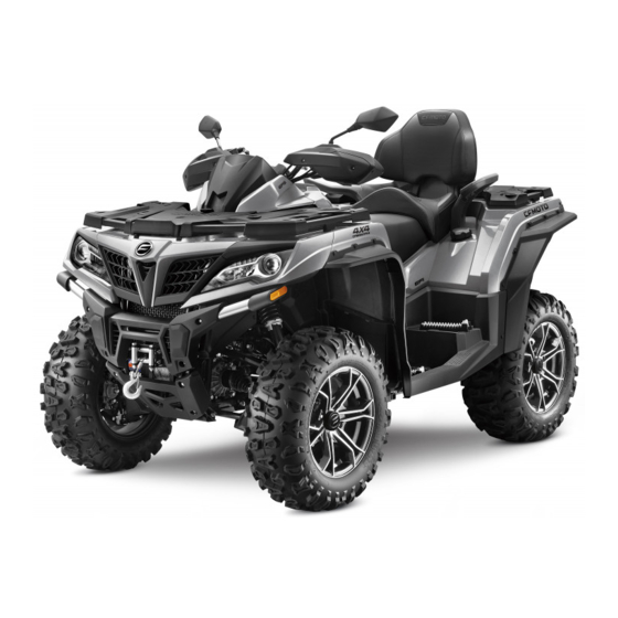
CFORCE 850XC
CFORCE 1000
CF800ATR-3
CF1000ATR
OWNER'S MANUAL
READ THIS MANUAL CAREFULLY
It contains important safety information
This ATV should not be ridden by anyone under
16 years of age. Passenger under 12 are
prohibited.
Table of
Contents
Previous
Page
Next
Page
1
2
3
4
5
Advertisement
Table of Contents
Need help?
Do you have a question about the CFORCE 850XC and is the answer not in the manual?
Ask a question
Questions and answers
Subscribe to Our Youtube Channel
Related Manuals for CF MOTO CFORCE 850XC
Offroad Vehicle CF MOTO CFORCE 1000 Owner's Manual
(183 pages)
Utility Vehicle CF MOTO CFORCE 850 Installation Instructions Manual
(53 pages)
Offroad Vehicle CF MOTO CFORCE 800XC Owner's Manual
(183 pages)
Offroad Vehicle CF MOTO ZFORCE 800EX Owner's Manual
(212 pages)
Offroad Vehicle CF MOTO ZFORCE 800TRAIL Owner's Manual
(212 pages)
Offroad Vehicle CF MOTO CFORCE CF400AU Owner's Manual
(189 pages)
Offroad Vehicle CF MOTO CFORCE 1000 2018 Service Manual
(366 pages)
Offroad Vehicle CF MOTO CFORCE 110 Owner's Manual
(152 pages)
Offroad Vehicle CF MOTO CF500 Service Manual
(259 pages)
Offroad Vehicle CF MOTO 600 Owner's Manual
(205 pages)
Offroad Vehicle CF MOTO Z FORCE 800 Trail Owner's Manual
(441 pages)
Offroad Vehicle CF MOTO UFORCE 1000 Owner's Manual
(181 pages)
Offroad Vehicle CF MOTO CF500-5 Service Manual
(254 pages)
Offroad Vehicle CF MOTO CF500-3/UTV Service Manual
(250 pages)
Offroad Vehicle CF MOTO CF500-A Owner's Manual
4x4 atv (146 pages)
Offroad Vehicle CF MOTO UFORCE 1000XL Owner's Manual
(197 pages)
This manual is also suitable for:
Cforce 1000
Cf800atr-3
Cf1000atr
Table of Contents
Save PDF
Print
Rename the bookmark
Delete bookmark?
Delete from my manuals?
Login
Sign In
OR
Sign in with Facebook
Sign in with Google
Upload manual
Upload from disk
Upload from URL


Need help?
Do you have a question about the CFORCE 850XC and is the answer not in the manual?
Questions and answers