Table of Contents

Related Manuals for CF MOTO CF400ATR-2S


Summary of Contents for CF MOTO CF400ATR-2S
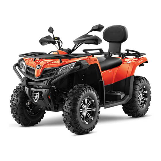
- Page 1 CFORCE 450 CF400ATR-2S/CF400ATR-2L CF500ATR-2S/CF500ATR-2L OWNER’S MANUAL READ THIS MANUAL CAREFULLY It contains important safety information This ATV should not be ridden by anyone under 16 years of age. Passenger under 12 are prohibited.
-
Page 2: Table Of Contents
TABLE OF CONTENTS Foreword Foreword ..........................................1 1 Welcome Welcome ................................................1 1 Signal Words Signal Words ..............................................2 2 Introduction Introduction ........................................5 5 Vehicle Identification Number Vehicle Identification Number ....................................5 5 Specification Specification ..............................................6 6 Operator Safety Operator Safety ................... - Page 3 Foot Controls Foot Controls ..............................................51 Vehicle Features Vehicle Features ..........................................52 CVT System CVT System ..............................................59 How To Avoid CVT Drive Belt and Component Failure How To Avoid CVT Drive Belt and Component Failure ....................60 Dashboard Indicators and Operation Dashboard Indicators and Operation ................
- Page 4 Cleaning and Storage Cleaning and Storage ................................152 Transporting the Vehicle Transporting the Vehicle ......................................156 Vehicle Issue Diagnosis Vehicle Issue Diagnosis................................ 157 Engine doesn’t turn over Engine doesn’t turn over ....................................157 Engine pings or knocks Engine pings or knocks ......................................157 Engine stops or loses power Engine stops or loses power ..................
- Page 5 FOREWORD Foreword Welcome Thank you for purchasing a CFMOTO vehicle, and welcome to our world-wide family of CFMOTO enthusiasts. Be sure to visit us at www.cfmoto.com for the latest news, new product introductions, upcoming events,and more. CFMOTO, an international company that specializes in the development, manufacture and marketing of large displacement motorcycles, all terrain vehicles, utility vehicles, and core components (power sports liquid cooling engines, frames,etc).
- Page 6 FOREWORD Signal Words A signal word calls attention to a safety message or messages, a property damage message or messages, and designates a degree or level of hazard seriousness. The standard signal words in this manual are WARNING, CAUTION and NOTE or NOTICE. Familiarize yourself with all laws and regulations concerning the operation of this vehicle in your area.
-
Page 7: Foreword Foreword
FOREWORD WARNING Improper vehicle use can result in SEVERE INJURY or DEATH NEVER Operate: • Without first viewing owner’ s manual and quick start guide. • Carrying more passengers than the rated passenger capacity. • Use ALCOHOL or DRUGS before or while driving this vehicle. •... -
Page 8: Signal Words Signal Words
FOREWORD WARNING FOR TYPE I VEHICLES (1-person vehicle) Improper vehicle use can result in SEVERE INJURY or DEATH ALWAYS NEVER CARRY NEVER USE AN PASSENGERS USE WITH APPROVED DRUGS OR HELMET AND ALCOHOL PROTECTIVE GEAR... - Page 9 FOREWORD WARNING FOR TYPE II VEHICLES (2-person vehicle) Improper vehicle use can result in SEVERE INJURY or DEATH ALWAYS NEVER NEVER USE AN CARRY MORE USE WITH APPROVED THAN ONE DRUGS OR HELMET AND PASSENGER ALCOHOL PROTECTIVE GEAR...
- Page 10 FOREWORD READ THE OWNER’S MANUAL FOLLOW ALL INSTRUCTIONS AND WARNINGS WARNING Read, understand, and follow all of the instructions and safety precautions in this manual and on all product labels. Failure to follow the safety precautions could result in serious injury or death. WARNING The engine exhaust gas from this product contains CO, which is deadly gas and could cause headache, giddy, disgusting or lose consciousness, even death.
-
Page 11: Introduction Introduction
Your key can be duplicated only by mating key blank with one of your existing keys. So if both keys are lost, the complete lock kits have to be replaced. CF400ATR-2S /CF500ATR-2S Vehicle identification number: CF400ATR-2L /CF500ATR-2L Vehicle identification number:... -
Page 12: Specification Specification
INTRODUCTION Specification Specification Item CF400ATR-2S CF500ATR-2S CF400ATR-2L CF500ATR-2L 2180 mm 2180 mm 2380 mm 2380 mm Overall Length 1100 mm 1100 mm 1100 mm 1100 mm Overall Width 1150 mm 1150 mm 1350 mm 1350 mm Overall Height 1260 mm... - Page 13 INTRODUCTION Item Specification Engine oil: SAE 5W-40 /SAE 10W-40 /SAE 15W-40 Type Engine oil volume 2.96 qt ( 2.8 L ) Capacity Change / Oil Filter Rear gear case oil Type SAE80W/90 GL-5 Volume 0.25 L Front gear case oil: Type SAE80W/90 GL-5 Volume...
- Page 14 INTRODUCTION Item Specification Fuel type 95(RON) or E10 Fuel tank capacity 15 L Fuel reverse amount 3.0 L Spark plug: DCPR8E ( NGK) Type 0.8 mm ~ 9 mm Spark plug gap Wet and centrifugal automatic Clutch type C(continuous variable transmission)(CVT) Transmission Type Manually/L-H-N-R-P Gear shift/order...
- Page 15 INTRODUCTION Item Specification Shock absorber: Coil spring/Oil damper Front shock absorber Coil spring/Oil damper Rear shock absorber Wheel travel: 180mm Front wheel travel 180mm Rear wheel travel Electric system Ignition A.C magneto Flywheel storage battery 12V 30A Light system Headlight type Front Turn light Front position light 12V E10W 10Wx2...
- Page 16 OPERATOR SAFETY Operator Safety WARNING Failure to heed the warnings contained in this manual can result in serious injury or death. An Vehicle is not a toy and can be hazardous to operate. This vehicle handles differently from other vehicles, such as motorcycles and cars.
-
Page 17: Operator Safety
OPERATOR SAFETY Equipment Modifications We are concerned with the safety of our customers and for the general public. Therefore,we strongly recommend that consumers do not install on an Vehicle any equipment that may increase the speed or power of the vehicle, or make any other modifications to the vehicle for these purposes. Any modifications to the original equipment of the vehicle create a substantial safety hazard and increase the risk of body injury. -
Page 18: Equipment Modifications Equipment Modifications
OPERATOR SAFETY Avoid Burns from Hot Parts Certain components become hot during operation. Avoid contact with those parts during and shortly after operation to avoid burns. Pulling a Trailer Check the maximum axle loads of the vehicle identification plate (statutory plate). CFMOTO vehicle can tow a trailer on the road. -
Page 19: Avoid Burns From Hot Parts Avoid Burns From Hot Parts
OPERATOR SAFETY Safety Training When you purchased your vehicle, your dealer offered a hands-on safety training course that covers all aspects of vehicle safety. You were also provided with printed materials that explain safe operating procedures. You should review this information on a regular basis. If you purchased a used Vehicle from a party other than a dealer, you can request safety training from any authorized dealer. -
Page 20: Safety Training Safety Training
OPERATOR SAFETY ●Never operate at excessive speeds. Travel at speeds appropriate for the terrain, visibility and operating conditions, and your experience. ●Never attempt wheelies,jumps or other stunts. ●Always inspect your vehicle before each use to make sure it’s in safe operating condition. ●Always follow the inspection schedules and maintenance outlined in your owner’s manual. - Page 21 OPERATOR SAFETY ●Always follow proper procedures for going downhill and for braking on hills: ▪ Check the terrain carefully before you start down a hill. ▪ Shift your weight backward. ▪ Never go down a hill at high speed. ▪ Avoid going down a hill at an angle,which would cause the vehicle to lean sharply to one side.
- Page 22 OPERATOR SAFETY ●Always be careful of skidding or sliding. On slippery surfaces like ice, travel slowly and use extra caution to reduce the chance of skidding or sliding out of control. ●Avoid operating the vehicle through deep or fast-flowing water. If it ‘s unavoidable,travel slowly, balance your weight carefully, avoid sudden movements, and maintain a slow and steady forward motion.
- Page 23 OPERATOR SAFETY WARNING POTENTIAL HAZARD: Operating this Vehicle without proper instruction. WHAT CAN HAPPEN: The risk of an accident is greatly increased if the operator does not know how to operate the Vehicle properly in different situations and on different types of terrain. HOW TO AVOID THE HAZARD: Beginning and inexperienced operators should complete a certified training course offered by a dealer.
- Page 24 OPERATOR SAFETY WARNING POTENTIAL HAZARD: Carrying a passenger on an Vehicle that is not designed for carrying a passenger. WHAT CAN HAPPEN: A passenger riding on the Vehicle could be ejected from the vehicle unexpectedly or make contact with moving components, both of which can result in severe injury or death.
- Page 25 OPERATOR SAFETY WARNING POTENTIAL HAZARD: Operating this Vehicle without wearing an approved helmet, eye protection and protective clothing. WHAT CAN HAPPEN Operating an Vehicle without an approved helmet increases the risk of a severe head injury or death in the event of an accident. Operating without eye protection could result in an accident and could increase the chance of a severe eye injury in the event of an accident.
- Page 26 OPERATOR SAFETY WARNING POTENTIAL HAZARD: Operating the Vehicle after consuming alcohol or drugs. WHAT CAN HAPPEN Consumption of alcohol and/or drugs could seriously affect operator judgment. Reaction time may be slower and operator balance and perception could be affected. Consumption of alcohol and/or drugs before or while operating an Vehicle could result in an accident causing severe injury or death.
- Page 27 OPERATOR SAFETY WARNING POTENTIAL HAZARD Operating the Vehicle at excessive speeds. WHAT CAN HAPPEN Excessive speed increase the operator’s chance of losing control of the Vehicle,which can result in an accident. HOW TO AVOID THE HAZARD Always operate the Vehicle at a speed that is proper for the terrain, visibility and operating conditions, and your experience.
- Page 28 OPERATOR SAFETY WARNING POTENTIAL HAZARD Failure to inspect the Vehicle before operating. Failure to properly maintain the Vehicle. WHAT CAN HAPPEN Poor maintenance increases the possibility of an accident or equipment damage. HOW TO AVOID THE HAZARD Always inspect your Vehicle before each use to make sure it’s in safe operating condition. Always follow the inspection and maintenance procedures and schedules described in the owner’s manual.
- Page 29 OPERATOR SAFETY WARNING POTENTIAL HAZARD Failure to use extra caution when operating the Vehicle on unfamiliar terrain. WHAT CAN HAPPEN Unfamiliar terrain may contain hidden rocks, bumps, or holes that could cause loss of control or overturn. HOW TO AVOID THE HAZARD Travel slowly and use extra caution when operating on unfamiliar terrain.
- Page 30 OPERATOR SAFETY WARNING POTENTIAL HAZARD Failure to use extra caution when operating on excessively rough, slippery or loose terrain. WHAT CAN HAPPEN Operating on excessively rough, slippery or loose terrain could cause loss of traction or loss of control, which could result in an accident or overturn.
- Page 31 OPERATOR SAFETY WARNING POTENTIAL HAZARD Turning improperly. WHAT CAN HAPPEN Improper turns could cause loss of control and lead to a collision or overturn. HOW TO AVOID THE HAZARD Always follow proper procedures or turning as described in the owner’s manual. Practice turning at slow speeds before attempting to turn at faster speeds.
- Page 32 OPERATOR SAFETY WARNING POTENTIAL HAZARD Climbing excessively steep hills or climbing hills improperly. WHAT CAN HAPPEN Improper hill climbing could cause loss of control or overturn. HOW TO AVOID THE HAZARD Always follow proper procedures for climbing hills as described in the owner’s manual.
- Page 33 OPERATOR SAFETY WARNING POTENTIAL HAZARD: Traveling down excessively steep hills. WHAT CAN HAPPEN: Improper downhill travel could cause loss of control or overturn. HOW TO AVOID THE HAZARD: Never operate on hills too steep for the Vehicle or for your abilities.
- Page 34 OPERATOR SAFETY WARNING POTENTIAL HAZARD Improperly crossing hills and turning on hills. WHAT CAN HAPPEN Improperly crossing or turning on hills could cause loss of control or overturn. HOW TO AVOID THE HAZARD Never attempt to turn the Vehicle around on any hill until you've mastered the turning technique on level ground as described in the owner' s manual.
- Page 35 OPERATOR SAFETY WARNING POTENTIAL HAZARD Stalling, rolling backwards or improperly dismounting while climbing a hill. WHAT CAN HAPPEN The vehicle could overturn. HOW TO AVOID THE HAZARD Maintain steady speed when climbing a hill. IF ALL FORWARD SPEED IS LOST: Close the throttle.
- Page 36 OPERATOR SAFETY WARNING POTENTIAL HAZARD Improperly operating over obstacles. WHAT CAN HAPPEN Operating over obstacles could cause loss of control or overturn. HOW TO AVOID THE HAZARD Before operating in a new area, check for obstacles. Avoid operating over large obstacles such as rocks and fallen trees when possible. If unavoidable,use extreme caution and always follow proper procedures as outlined in the owner’...
- Page 37 OPERATOR SAFETY WARNING POTENTIAL HAZARD Skidding or sliding. WHAT CAN HAPPEN Skidding or sliding can cause loss of control. If the tires regain traction unexpectedly, the Vehicle could overturn. HOW TO AVOID THE HAZARD On slippery surface such as ice, travel slowly and use extra caution to reduce the chance of skidding or sliding out of control.
- Page 38 OPERATOR SAFETY WARNING POTENTIAL HAZARD Operation the Vehicle through deep or fasten-following water. WHAT CAN HAPPEN The tires may float, causing loss of traction and loss of control, which lead to an accident or overturn. HOW TO AVOID THE HAZARD Avoid operating the Vehicle through deep or fast-flowing water.
- Page 39 OPERATOR SAFETY WARNING POTENTIAL HAZARD Improperly operating in reverse. WHAT CAN HAPPEN The Vehicle could collide with an obstacle or person, resulting in severe injury. HOW TO AVOID THE HAZARD Before shifting into reverse gear, always check for obstacles or people behind the Vehicle. When it' s safety to proceed, back slowly.
- Page 40 OPERATOR SAFETY WARNING POTENTIAL HAZARD Operating the Vehicle with improper modifications. WHAT CAN HAPPEN Improper installation of accessories or modification of the Vehicle may cause changes in handling which could lead to an accident. HOW TO AVOID THE HAZARD Never modify the Vehicle through improper installation or use of accessories. All parts and accessories added to the vehicle must be genuine parts or equivalent components designed for use on this Vehicle and should be installed and used according to approved instructions.
- Page 41 OPERATOR SAFETY WARNING POTENTIAL HAZARD Improper dismantling and disposal of hazardous materials. WHAT CAN HAPPEN It could damage the environment. HOW TO AVOID THE HAZARD ALWAYS BE ENVIRONMENTALLY RESPONSIBLE Follow the guidelines of the governmental agency for the proper disposal of hazardous materials such as engine oil, fuel, engine coolant and machine fluid, grease.
- Page 42 OPERATOR SAFETY WARNING Leaving the keys in the ignition can lead to unauthorized use of the vehicle, resulting in serious injury or death. Always remove the ignition key when the vehicle is not in use. WARNING After any overturn or accident, have a qualified service dealer inspect the entire vehicle for possible damage, including (but not limited to) brakes, throttle and steering systems.
- Page 43 OPERATOR SAFETY Safe Riding Gear Always wear clothing suited to the type of riding. Vehicle riding requires special protective clothing for comfort and to reduce the chance of injury. 1 . Helmet Your helmet is the most important piece of protective gear for safe riding.
-
Page 44: Safe Riding Gear Safe Riding Gear
SAFETY DECALS & LOCATIONS Safety Decals and Locations Warning decals have been placed on the Vehicle for your protection. Read and follow the instruction on each decal carefully. If a decal becomes illegible or comes off, contact your dealer to purchase a replacement. -
Page 45: Safety Decals And Locations Safety Decals And Locations
SAFETY DECALS & LOCATIONS CF400ATR-2S/CF500ATR-2S CF400ATR-2L/CF500ATR-2L CF400ATR-2S/CF500ATR-2S CF400ATR-2S/CF500ATR-2S CF400ATR-2S/CF500ATR-2S CF400ATR-2L/CF500ATR-2L CF400ATR-2L/CF500ATR-2L CF400ATR-2L/CF500ATR-2L... - Page 46 SAFETY DECALS & LOCATIONS CF400ATR-2S/CF500ATR-2S...
- Page 47 FEATURES & CONTROLS CF400ATR-2L/CF500ATR-2L CF400ATR-2L/CF500ATR-2L...
- Page 48 FEATURES & CONTROLS Features and Controls Left Hand Controls Override Button Top speed is normally limited when operating in 4WD-LOCK and REVERSE. If conditions require more engine power when proceeding, press this button to override the speed limiting function. Releasing the button restores the speed limiting function.
-
Page 49: Features And Controls Features And Controls
FEATURES & CONTROLS Headlight Switch The headlight switch consists of 4 positions: “ ”, “ ”,“OFF”. : When the switch is at this position, Hi beam, tail light, instrument light and license plate light are on. : When the switch is at this position, Lo beam, tail light, instrument light and license plate light are on. OFF: When the switch is at this position, all lights are off. - Page 50 FEATURES & CONTROLS Horn Button Press the button “ ”. The horn will sound. Engine Stop Switch : When the switch is moved to this position, the engine shuts off. : When the switch is moved to this position, the engine can be started.
- Page 51 FEATURES & CONTROLS Right Hand Controls Front Brake The front brake lever is located on the right handlebar and controls only the front brakes. Pull it toward the handlebar to apply the front brake. When squeezed, the lever should feel firm.
-
Page 52: Right Hand Controls Right Hand Controls
FEATURES & CONTROLS 2WD / 4WD System Switch This vehicle is equipped with an on-command four-wheel drive switch “2WD”/”4WD” and a front diff-lock switch “LOCK”/”4WD” .Select the appropriate drive according to terrain and the conditions. ●Two-wheel drive ( 2WD ) :Power is supplied to the rear wheels only. - Page 53 FEATURES & CONTROLS Front Diff-lock Switch “LOCK”/”4WD” To lock the front diff in 4WD, make sure the on-command four- wheel-drive switch is set to 4WD, stop the vehicle, move the lever to 2WD/4WD switch, then set the switch to LOCK, when the front diff is locked, the The 4WDLOCK indicator “...
- Page 54 FEATURES & CONTROLS Throttle Lever Before starting the engine, check the throttle to be sure it is operating smoothly. Make sure it returns to the idle position as soon as the lever is released. Once the engine is running, movement of the throttle lever using your thumb will increase the engine speed.
- Page 55 FEATURES & CONTROLS Mechanical Speed Limiter A mechanical speed limiter keeps the throttle from fully opening, even when the throttle lever is pushed to the maximum travel. Turning the screw limits the throttle lever travel, which reduces the maximum engine power available and decreases the maximum speed of the vehicle.
- Page 56 FEATURES & CONTROLS Foot Controls Foot Brake The foot brake pedal is located on the right side floor board of the vehicle. Push down on the pedal to apply both the front and rear brakes. When pressed, the pedal should feel firm. A soft brake pedal would indicate a possible fluid leak or low master cylinder fluid level, which must be corrected before riding.
-
Page 57: Foot Controls Foot Controls
FEATURES & CONTROLS Vehicle Features Main Switch Functions of the respective switch positions are as follows: :The engine can be started only at this position and the headlights and taillight come on when the light switch is on. The key can not be removed in this position. :All electrical circuits are switched off. -
Page 58: Vehicle Features Vehicle Features
FEATURES & CONTROLS Fuel Tank The fuel tank fill cap is located at the top of the vehicle behind the handlebars. Cap removal is left-handed rotation. Cap installation is right-handed rotation. Fuel Minimum Octane Rating The recommended fuel for your Vehicle is minimum 95 Octane unleaded. - Page 59 FEATURES & CONTROLS Fuel safety WARNING Gasoline is highly flammable and explosive under certain conditions. ●Always exercise extreme caution whenever handling gasoline. ●Always refuel with the engine stopped, and outdoors or in a well ventilated area. ●Never carry a plastic container with gasoline in the racks while riding. Static electricity between the rack and container could cause a spark.
- Page 60 FEATURES & CONTROLS Transmission Gear Selector The transmission gear selector is located on the left side of the vehicle: Gear Pattern L – Low Gear H – High Gear Selector Direction R – Reverse Gear P – Park CAUTION Always stop the Vehicle and press the foot brake pedal before shifting the transmission.
- Page 61 FEATURES & CONTROLS Parking When parking, stop the engine and shift the gear selector Lever into the park position. CAUTION: When shifting the transmission in PARK, always push the brake pedal. Shake the vehicle forward and backward to check if the parking brake is engaged.
- Page 62 FEATURES & CONTROLS 12 Volt Accessory and USB Power Auxiliary 12Vdc and USB power outlets are provided on the left side front fender area for operating accessories such as hand held spot lights and charging electronic devices. Please consult with your dealer on the use of powered accessories with your vehicle.
- Page 63 FEATURES & CONTROLS Trailer Power Socket This vehicle is equipped with 7-pin trailer power socket, located under the rear cargo rack. The socket wires are configured to this standard as shown in the image provided . An accessory trailer power converter is required for trailers that do not have a 7-pin connector.
- Page 64 FEATURES & CONTROLS GENERAL SAFETY PRECAUTIONS REGARDING THE USE OF WINCH Prior to initiating winching operation be sure any element which Moving Part Hazards can interfere with safe winching is removed. To prevent serious injury and property damage: Do not disengage clutch if winch is under load or wire rope is in Do not operate or install winch without reading and tension. understanding these instructions and the Basic Guide to Take your time. Sloppy rigging causes accidents. Winching Techniques. The wire rope must always spool onto the drum as indicated by Keep hands clear of wire rope, hook and fairlead opening during the drum rotation label on the winch. ...
-
Page 65: Cvt System Cvt System
FEATURES & CONTROLS CVT System This vehicle has a Continuously Variable Transmission (CVT) system that utilizes a belt and clutch pulleys to automatically vary transmission ratios, allowing infinite variability between the highest and lowest vehicle speeds with no discrete steps or shifts. -
Page 66: How To Avoid Cvt Drive Belt And Component Failure How To Avoid Cvt Drive Belt And Component Failure
FEATURES & CONTROLS How To Avoid CVT Drive Belt and Component Failure CVT clutch and belt life can be dramatically extended by avoiding these common operating mistakes: Causes CVT damage: Solution: Attempting to load the vehicle onto a truck bed or tall Shift transmission to low gear during loading of the trailer in high gear. - Page 67 FEATURES & CONTROLS Causes CVT damage: Solution: Climbing over large objects from a stopped position. Shift the transmission to low gear, and carefully use fast, brief, aggressive throttle application to engage the CVT. WARNING: Excessive throttle may cause loss of control and vehicle overturn.
-
Page 68: Dashboard Indicators And Operation Dashboard Indicators And Operation
FEATURES & CONTROLS Dashboard Indicators and Operation Indicators and Warnings Tuning Indicators Brake failure indicator EFI indicator Operator presence control Gear indicators Override indicator High Beam Indicators Park indicator... - Page 69 FEATURES & CONTROLS Turning Indicators: Includes Left turning indicator and right turning indicator. Move the switch to this position , left turn signal indicator will be on. Move the switch to this position , right turn signal indicator will be on. Press the button , front and rear turning lights, turn signal indicators on the dashboard will be on.
- Page 70 FEATURES & CONTROLS Indicators and Warnings Dashboard Oil pressure warning light 4 Speedometer 7 Coolant temperature gauge Drive method indicator 5 Rider information center 8 Clock indicator Fuel gauge 6 EPS indicator...
- Page 71 FEATURES & CONTROLS Indicators and Warnings 1.Oil Pressure warning light: When the engine oil pressure is abnormal, this warning indicator is on,and will be off when it’s normal. 2.Drive Method Indicator : It will display 2WD, 4WD or 4WD-LOCK drive method as chosen. 3.Fuel Gauge: Indicates the fuel level in the fuel tank.
- Page 72 FEATURES & CONTROLS 6.EPS Indicator: This indicator light flashes when a fault occurs in the Electronic Power Steering system. 7.Coolant Temperature Gauge: Displays the current coolant temperature, ‘C’ is low temperature, ‘H’ is high temperature. Both over-low and over-high are abnormal. Idle the vehicle to warm the engine when it’s too cold, and park the vehicle when it’s too hot to prevent the coolant from boiling.
- Page 73 FEATURES & CONTROLS Dashboard Navigation / Settings / Adjustments Item Display SEL / ADJ Button Result Metric / Standard Toggle Speed/Distance Long Press ‘SEL’ Metric ↔Standard Values Vehicle Odometer Trip Distance ODO→TRIP→RPM→H→ Engine RPM Distance/RPM/Item Toggle Short Press ‘SEL’ Engine Hour V→L-I-g-H--5→ODO Battery Voltage Brightness Setting...
-
Page 74: Operation Of Your Vehicle Operation Of Your Vehicle
OPERATION OF YOUR ATV Operation of Your Vehicle Break-In Period The break-in period for your new Vehicle is very important. Careful treatment of a new engine will result in more efficient performance and longer life for the engine. Perform the following procedures carefully. 1. - Page 75 OPERATION OF YOUR ATV CAUTION During the break-in period: • Do not load or tow cargo. • Do not operate at sustained full throttle. Damage to engine parts or decrease engine life may result if excessive wide open throttle is used during the first 20 hours of use. •...
-
Page 76: Pre-Ride Inspection Pre-Ride Inspection
OPERATION OF YOUR ATV Pre-Ride Inspection Perform the following procedures before operation: 1. Fill the fuel tank with gasoline. 2. Place the vehicle on a level ground to check the engine oil level. Add recommended engine oil if necessary to maintain the oil level between the minimum and maximum level marks of the dipsticks. 3. -
Page 77: Starting The Engine Starting The Engine
OPERATION OF YOUR ATV Starting the Engine WARNING Engine exhaust contains poisonous carbon monoxide and can cause loss of consciousness resulting in severe injury or death. Never run an engine in an enclosed area. CAUTION Operating the vehicle immediately after starting could cause engine damage. Allow the engine to warm up for several minutes before operating the vehicle. - Page 78 OPERATION OF YOUR ATV NOTE ●When the gear selector is in neutral position,if indicator light on dashboard does not come on,ask your dealer to inspect its electric circuit or adjust gear-shifting system. ●Engine can be started in any gear if rear brake pedal is applied. However it is recommended to shift into neutral or park before starting the engine.
-
Page 79: Gear Selector Operation Gear Selector Operation
OPERATION OF YOUR ATV Gear Selector Operation Shifting CAUTION To avoid transmission damage, return the throttle to the closed position, stop the vehicle, and apply the foot brake before shifting. NOTE Low gear is the preferred transmission gear selection for all forward motion other than prolonged high speed travel. - Page 80 OPERATION OF YOUR ATV Shifting: Low Gear to High Gear 1. Verify the throttle is closed and the vehicle is stopped completely. 2. Apply the foot brake. 3. Shift to ‘H’ by moving the gear selector along the shift guide. Shifting: to Reverse Gear 1.
- Page 81 OPERATION OF YOUR ATV NOTE The gear selector must not be shifted into reverse gear without applying the foot brake. The gear shift indicators should display corresponding to the actual gear position, if the indicator does not display, ask your dealer to inspect the vehicle electrical circuit or adjust the gear shifting system. Due to the synchronizing mechanism in the engine, an indicator may not display until Vehicle starts moving.
-
Page 82: Hauling And Towing Cargo Hauling And Towing Cargo
OPERATION OF YOUR ATV Hauling and Towing Cargo Your vehicle is equipped with front and rear cargo racks, and a hitch receptacle for towing. Follow these guidelines for hauling and towing of cargo: WARNING Overloading the vehicle or carrying or towing cargo improperly can alter vehicle handling and may cause loss of control or brake instability. - Page 83 OPERATION OF YOUR ATV • When operating with loads extending beyond the rack. Stability and maneuverability may be adversely affected,causing the machine to overturn. • Carrying a load on only the front rack or the rear rack may cause an imbalanced condition and increases the possibility of vehicle overturn.
-
Page 84: Load Distribution Load Distribution
OPERATION OF YOUR ATV Load Distribution Your vehicle has been designed to carry or tow a certain amount of load. Always read and understand the load distribution warnings listed on the warning labels, and never exceed the specified weights. Cargo weight should be mounted as low as possible. - Page 85 OPERATION OF YOUR ATV MAXIMUM HAULING CAPACITY TRAILER TONGUE LOAD WEIGHT NOTE ALLOWED ALLOWED CF400ATR-2S Includes trailer and trailer load. 300 kg CF500ATR-2S Ensure to properly load the trailer Trailer without 25 kg so that tongue is always pushing on brakes...
- Page 86 OPERATION OF YOUR ATV Place a support under vehicle. NOTE: Before jacking ensure that all wheels are locked. NOTE: When the brake lock is applied ensure that the vehicle stays securely in place. WARNING DO NOT OVERLOAD your jack beyond its rated capacity. Use jack which is designed for use on hard level surfaces only.
- Page 87 OPERATION OF YOUR ATV Intended Use The vehicle is designed solely for use in agricultural or similar operations. Use in any other way is considered as contrary to the intended use. Compliance with and strict adherence to the conditions of operation, service, and repair as specified by the manufacturer, also constitute essential elements of the intended use.
- Page 88 OPERATION OF YOUR ATV Hauling a Load (If equipped with hitch) Never pull a load by attaching it to the cage. It can cause the vehicle to tip stalled to pull a load. In an emergency situation, use the recovery hook to recover a stuck vehicle. When pulling loads with a chain or cable, ensure that there is no slack before starting and maintain tension while pulling.
- Page 89 OPERATION OF YOUR ATV Where a designated attachment point is provided on the towbar: Either b)Attach the clip directly to the designated a) Pass the cable through the attachment point ( FIG.2 ).This alternative must point and clip it back on itself ( FIG.1 ) be specifically permitted by the trailer manufacturer since the clip may not be sufficiently strong for use in this way.
-
Page 90: Driving Safely Driving Safely
OPERATION OF YOUR ATV Driving Safely Responsibilities of the operator As the operator of this vehicle, your common sense, judgment, and abilities are the only factors that will prevent injury to yourself, to others around you, and/or damage to the vehicle or environment. Recreational, group, and distance riding Always keep a safe distance from other riders ahead of you and behind you when riding in a group. - Page 91 OPERATION OF YOUR ATV Practice The driving procedures described in this manual should be practiced at slow speed many times in a large area with no obstacles. If an incorrect technique is used, your vehicle may continue to go straight. If the vehicle does not turn, stop and practice the procedure again.
- Page 92 OPERATION OF YOUR ATV Driving Procedures 1. Sit upright with both feet on the footrests and both hands on the handlebars. 2. Start the engine and allow it to warm up, apply the brakes, then shift the transmission into gear. 3.
- Page 93 OPERATION OF YOUR ATV Making Turns To make a turn, steer in the direction of the turn, leaning your upper body to the inside of the turn while supporting your weight on the outer footrest. This technique alters the balance of traction between the wheels, allowing turn to be made smoothly.
- Page 94 OPERATION OF YOUR ATV Vehicle turning dynamics To achieve maximum traction while operating in 2WD or 4WD, the two rear wheels perform as one axle and turn together at the same speed. Furthermore, when operating in 4WD-LOCK mode, the front wheels will also turn together at the same speed.
- Page 95 OPERATION OF YOUR ATV Driving in reverse To operate in reverse: 1. Ensure the throttle is closed and the vehicle is stopped completely. 2. Apply the foot brake, then shift the transmission into reverse gear. 3. Check for obstacles or people behind the vehicle. 4.
- Page 96 OPERATION OF YOUR ATV Driving on slippery surfaces Whenever driving on slippery surfaces such as wet trails, loose gravel, sand, or during freezing weather, follow these precautions: • Slow down when entering slippery areas. • Maintain a high level of alertness, reading the trail in front of you as you drive.
- Page 97 OPERATION OF YOUR ATV Driving on rough terrain Whenever driving on rough surfaces such as trails with large rocks or other obstacles, follow these precautions: • Slow down when encountering rough terrain. • Maintain a high level of alertness, reading the trail in front of you as you drive.
- Page 98 OPERATION OF YOUR ATV Driving through water Your Vehicle can operate through water with a maximum recommended depth equal to the bottom of the footrests. Follow these procedures when operating through water: • Determine water depths and current before crossing. •...
- Page 99 OPERATION OF YOUR ATV Drying the CVT system after submersion If water has been ingested into the CVT housing, the drive belt will likely slip and poor performance will result. To expel water and dry the CVT housing; Drain the CVT housing, place the vehicle in neutral, and raise the engine rpm for several minutes to dry the CVT components.
- Page 100 OPERATION OF YOUR ATV Driving Uphill Whenever traveling uphill, follow these precautions: • Always travel straight uphill. • Avoid steep hills (20 maximum). • Keep both feet on the footrests. • Shift your weight forward. • Maintain a steady rate of speed and throttle opening. •...
- Page 101 OPERATION OF YOUR ATV If the Vehicle begins rolling backwards: Keep your weight uphill. Never apply engine power. Never apply the foot brake while rolling backwards. Apply the front brake. When fully stopped, apply the rear brake and shift the gear selector into park position.
- Page 102 OPERATION OF YOUR ATV Sidehilling WARNING Improperly crossing hills or turning on hills can result in loss of control or vehicle overturn, resulting in severe injury or death. Avoid crossing the side of a hill when possible. Follow proper procedures as outlined in the owner s manual. Sidehilling can be a dangerous type of driving and should be avoided if at all possible.
- Page 103 OPERATION OF YOUR ATV Driving downhill When traveling down a hill, follow these precautions: • Never operate on hills over 22 degrees incline or hills too steep for your abilities. • Slow down. • Shift your weight to the rear of the vehicle. •...
- Page 104 OPERATION OF YOUR ATV Turning Around on a Hill One maneuver that can be used when it’s necessary to turn around if stranded while climbing a hill is the K-turn: 1. Release the throttle, then apply the hand and foot brake while keeping your body weight uphill.
- Page 105 OPERATION OF YOUR ATV Parking on an incline Avoid parking on an incline if possible. If it’s unavoidable, follow these precautions: • Turn the engine off. • Place the gear selector to parking position. • Always block the rear wheels on the downhill side. Refer to the illustration.
-
Page 106: Maintenance Maintenance
MAINTENANCE & LUBRICATION Maintenance Following the maintenance schedule in your owner’s manual will help keep your vehicle in the safest, most reliable condition. Inspection, adjustment, and lubrication of important components are explained in the maintenance schedules. Inspect, clean, lubricate, adjust, and replace parts as necessary. When inspection reveals the need for replacement parts, please use genuine parts available from your dealer. -
Page 107: Periodic Maintenance Schedule And Icon Key Periodic Maintenance Schedule And Icon Key
MAINTENANCE & LUBRICATION NOTE Pay special attention to the engine oil level during cold weather operation. A rise in engine oil level can indicate contaminants collecting in the oil sump or crankcase. Change oil immediately if the oil level begins to rise. - Page 108 MAINTENANCE & LUBRICATION KEY POINTS OF LUBRICATION SCHEDULE: Check all components at the intervals outlined in the Periodic Maintenance Schedule. Items not listed in the schedule should be lubricated at the general lubrication interval. • Change lubricants more often under severe use, such as wet or dusty conditions. •...
-
Page 109: Pre-Ride Maintenance Checklist Pre-Ride Maintenance Checklist
MAINTENANCE & LUBRICATION Pre-Ride Maintenance Checklist Perform these inspections before operating the vehicle: Maintenance before operation Item Hour Calendar Miles (km) Remarks Pre-Ride ■ Steering system Pre-Ride ■ Throttle return Pre-Ride Front suspension and axles Visually inspect, test, Pre-Ride Rear suspension and axles or check components. - Page 110 MAINTENANCE & LUBRICATION Maintenance before operation Item Hour Calendar Miles (km) Remarks Inspect. If deposits are visible, clean intake Pre-Ride ► Air box sediment tube tubes, air box, and replace air filter. Inspect. If deposits are visible, drain / clean Pre-Ride ►...
-
Page 111: Break-In Maintenance Checklist Break-In Maintenance Checklist
MAINTENANCE & LUBRICATION Break-In Maintenance Checklist Perform these maintenance items when the vehicle break-in is completed: Break-in Maintenance (Perform at the interval that arrives first) Item Hour Calendar Miles (km) Remarks Lubricate all grease 200 (320) General lubrication points, pivots, cables, etc. - Page 112 MAINTENANCE & LUBRICATION Break-in Maintenance (Perform at the interval that arrives first) Item Hour Calendar Miles (km) Remarks Check terminals, 200 (320) Battery clean, test battery condition if required. Inspect for proper rpm. See dealer for 200 (320) ■ Idle condition service if out of spec or erratic.
-
Page 113: Periodic Maintenance Schedule Periodic Maintenance Schedule
MAINTENANCE & LUBRICATION Periodic Maintenance Schedule Perform these maintenance items when the vehicle break-in is completed: Periodic Maintenance Intervals (Perform at the interval that arrives first) Item Hour Calendar Miles (km) Remarks Monthly 100 (160) ► Brake pads Inspect pad thickness. Check terminals. - Page 114 MAINTENANCE & LUBRICATION Periodic Maintenance Intervals (Perform at the interval that arrives first) Item Hour Calendar Miles (km) Remarks Inspect level. Change 500 (800) ► Front gear case oil yearly if hours or distance interval is not met. Inspect level. Change 500 (800) ►...
- Page 115 MAINTENANCE & LUBRICATION Periodic Maintenance Intervals (Perform at the interval that arrives first) Item Hour Calendar Miles (km) Remarks Inspect; clean external surfaces. 500 (800) Clean more frequently if ► Radiator subjected to severe use. 500 (800) Inspect. Lubricate. ■ Steering system 500 (800) Lubricate.
- Page 116 MAINTENANCE & LUBRICATION Periodic Maintenance Intervals (Perform at the interval that arrives first) Item Hour Calendar Miles (km) Remarks Inspect. Replace as 1500 (2400) ► ■ CVT drive belt necessary. See dealer for service. Clean and Inspect pulleys. Replace worn 100h 500 (800) ■...
- Page 117 MAINTENANCE & LUBRICATION Periodic Maintenance Intervals Item (Perform at the interval that arrives first) Hour Calendar Miles (km) Remarks Inspect fuel tank, cap, ● 100h 500 (800) Fuel system fuel pump and fuel pump relay. Inspect; Replace if 100h 2000 (3200) Spark plug worn or fouled.
- Page 118 MAINTENANCE & LUBRICATION Periodic Maintenance Intervals Item (Perform at the interval that arrives first) Hour Calendar Miles (km) Remarks Inspect for noise or ► ■ Wheel bearings 100h 1500 (2400) looseness Replace as necessary. Visually inspect belts and test latches. Clean latch Safety Belts 100h 2000 (3200)
- Page 119 MAINTENANCE & LUBRICATION Periodic Maintenance Intervals (Perform at the interval that arrives first) Item Hour Calendar Miles (km) Remarks Inspect for proper rpm. See dealer for Idle condition service if out of spec or erratic. Inspect steering system. See dealer for service whenever Steering / Wheel Alignment ■...
-
Page 120: Maintenance Procedures Maintenance Procedures
MAINTENANCE & LUBRICATION Maintenance Procedures Engine oil check Always check and change the engine oil at the intervals outlined in the Maintenance Schedule. 1. Place the Vehicle on a level surface. 2. Start the engine and let it idle for (20~30) seconds. Stop the engine. - Page 121 MAINTENANCE & LUBRICATION Engine oil and filter change 1. Place the Vehicle on a level surface. 2. If the engine was running, wait a sufficient period for the oil to settle and cool. Crankcase drain and sump filter service 3. Place an oil pan under the engine to collect the used oil. 4.
- Page 122 MAINTENANCE & LUBRICATION Oil filter cartridge replacement 1. If necessary, remove the left cover panel to access the oil filter location. Remove the oil filter cover fasteners cover from the crankcase. 2. Remove the oil filter cartridge from the crankcase housing.
- Page 123 MAINTENANCE & LUBRICATION Rear gear case oil measurement 1. Place the vehicle on a level surface. 2. Remove the oil filler bolt and check the oil level. The level should be up to the brim of the hole. If the level is low, add sufficient oil to raise it to the specified level.
- Page 124 MAINTENANCE & LUBRICATION Front gear case oil measurement. 1. Place the machine on a level surface. 2. Remove the oil filler bolt and check the oil level. It should be up to the brim of the hole. If the level is low, add sufficient oil to raise it to the specified level.
- Page 125 MAINTENANCE & LUBRICATION Front access cover Removal: Grasp the access cover edge, pull upward to release the grommet pins, then remove the front access cover direction of front of vehicle. Install: Insert the cover tabs into the corresponding holes on the body, then align the grommet pins and press down.
- Page 126 MAINTENANCE & LUBRICATION Cooling system Coolant level inspection 1. Place the Vehicle on a level surface. 2. Check the coolant level in the coolant reservoir when the engine is cold as the coolant level will vary with engine temperature. 3. If the coolant is at or below the lower limit mark, remove the access cover and the reservoir cap , add coolant to the upper limit mark, install the reservoir cap, and then install...
- Page 127 MAINTENANCE & LUBRICATION Change the coolant CAUTION After running the engine, never remove the radiator cap immediately. Wait for the engine to cool down before removing the radiator cap. Hot coolant can cause serious burns. 1. Place the Vehicle on a level surface. 2.
- Page 128 MAINTENANCE & LUBRICATION 6. Disconnect the hose from the coolant reservoir, and drain the coolant into a container. 7. After draining the system, thoroughly flush the system with clean tap water. Allow the water to drain completely from the coolant drain. 8.
- Page 129 MAINTENANCE & LUBRICATION 14. Install the coolant reservoir cap and check for coolant leaks. If any leaks are found, have your dealer check the cooling system. 15. Reinstall: ▪ The engine left cover. Tighten the fasteners to 7.3 ft-lb. (10 N•m). ▪...
- Page 130 MAINTENANCE & LUBRICATION Front and rear axles The front and rear axle dust boots must be checked for holes or wear before operating. If any damage is found, have your dealer check and repair the vehicle.
- Page 131 MAINTENANCE & LUBRICATION Spark plug The spark plug is an important engine component that is easy to inspect. The color and condition of the spark plug can indicate the condition of the engine. The ideal color on the insulator around the center electrode is a medium-to-light tan color for an engine that is being operated normally.
- Page 132 MAINTENANCE & LUBRICATION 3. Use the spark plug socket and wrench from the tool kit to remove the spark plug. 4. Check the spark plug gap (A) using a thickness gauge. Adjust the gap if necessary. NOTE Specified spark plug: DCPR8E (NGK) Spark plug gap: 0.035 in.
- Page 133 MAINTENANCE & LUBRICATION Spark plug removal to expel water from the engine If water has been ingested into the engine, it is important to remove the water as soon as possible by removing the spark plug and using the starter system to rotate the engine for a short period to expel water out of the cylinder.
- Page 134 MAINTENANCE & LUBRICATION Air filter Always check and change the engine oil at the intervals outlined in the Maintenance Schedule. The air filter element should be cleaned more often if the machine is operated in extremely dusty or wet areas. There is a check hose at the bottom of the air filter housing.
- Page 135 MAINTENANCE & LUBRICATION 3. Loosen the air filter clamp and remove the air filter 4. Remove the foam pre-filter from the air filter. 5. Wash the foam pre-filter gently with soap and water, and allow it to completely dry. 6. Inspect the paper air filter and verify it is okay to reinstall. Softly brush off accumulated dust if necessary.
- Page 136 MAINTENANCE & LUBRICATION Drying the air filter housing after submersion If water has been ingested into the air filter housing, Drain the air filter housing, remove the air filter, and thoroughly dry the components. Do not use compressed air. Contact your dealer if vehicle performance issues exist.
- Page 137 MAINTENANCE & LUBRICATION Exhaust spark arrestor Clean carbon deposits from the spark arrester while the muffler and exhaust are in normal air temperature. 1. Remove the fasteners 2. Tap the tailpipe lightly to loosen it and remove the spark arrester from the muffler.
- Page 138 MAINTENANCE & LUBRICATION Throttle body adjustment The throttle body is a vital part of the engine and requires very sophisticated adjustment. Most adjusting should be left to your dealer who has the professional knowledge and experience to do so. However, the idling speed may be performed by the owner as a part of the usual maintenance routine.
- Page 139 MAINTENANCE & LUBRICATION Brakes Front brake pad inspection Inspect the front brake pads and discs for damage and wear. If the pad thickness is less than 0.059 in. (1.5mm) or the disc thickness is less than 0.118 in. (3.0mm), have your dealer replace them.
- Page 140 MAINTENANCE & LUBRICATION Rear brake pad inspection Inspect the brake pads and rear brake discs for damage and wear. If the pad thickness “a” is less than 1.5mm or the disc thickness “b” is less than 4.0mm, then have your dealer replace them.
- Page 141 MAINTENANCE & LUBRICATION Brake fluid level inspection Before riding, check that the brake fluid levels are above the lower mark and replenish whenever necessary. Insufficient brake fluid may let air enter the brake system, possibly causing the brakes to become ineffective. The front brake fluid master cylinder reservoir level is located on the right handlebar.
- Page 142 MAINTENANCE & LUBRICATION Observe these precautions: 1. When checking the fluid level, make sure the top of the master cylinder reservoir is level by turning the handlebars. 2. Use only the designated quality brake fluid. Otherwise, the rubber seals may deteriorate, causing leakage and poor brake performance.
- Page 143 MAINTENANCE & LUBRICATION Front brake lever freeplay The front brake lever should have zero in. (zero mm) free play of at the lever end. If free play is present, have your dealer check the brake system. DANGER(After servicing): Make sure the brakes operate smoothly and that the free play is correct;...
- Page 144 MAINTENANCE & LUBRICATION Foot brake pedal hight adjustment NOTE Inspect the rear brake pad thickness before adjusting the foot brake. The top of the brake pedal should be positioned 70mm ~ 80mm above the top of the footrest. If not,ask your dealer to adjust it.
- Page 145 MAINTENANCE & LUBRICATION Control Cables Inspection and lubrication Inspect cables frequently. Replace damaged cables. Lubricate the inner cables and the cable ends. If the cables do not operate smoothly, ask your dealer to replace them. NOTE Recommended lubricant: SAE 10W-30 or a commercially available cable lubricant.
- Page 146 MAINTENANCE & LUBRICATION Suspension Front suspension lubrication The front suspension of the vehicle contains components that require no maintenance or lubrication. Ensure the components are cleaned regularly, and are not loose or damaged before operating the vehicle. Rear suspension lubrication Lubricate the upper and lower pivots of the rear axles: 1.
- Page 147 MAINTENANCE & LUBRICATION Front and rear suspension adjustment The front and rear suspension spring preload can be adjusted to suit the rider's weight and riding conditions. NOTE When adjusting the rear shock absorbers, the rear wheels need to be removed. Adjust the spring preload as follows.
- Page 148 MAINTENANCE & LUBRICATION Wheels Wheel removal 1. Loosen the wheel nuts. 2. Elevate the Vehicle and place a suitable stand under the frame. 3. Remove the nuts from the wheel. 4. Remove the wheel. Wheel installation: 1. Install the wheel and the nuts. 2.
- Page 149 MAINTENANCE & LUBRICATION Wheels Tire pressure Inspect the tire pressure before operation: Front: 8.0 psi (56 kPa) Rear: 6.0 psi (42 kPa) Tread depth Inspect the tread depth regularly and replace the tires if the minimum tread depth is less than: Minimum tread depth: 3/32 in.
- Page 150 MAINTENANCE & LUBRICATION Battery This vehicle is equipped with a 12 volt / 30 Amp hour, sealed low-maintenance battery, which is located under the seat. Therefore, it is not necessary to check the electrolyte or add distilled water to the battery. If the battery seems to have discharged, consult your dealer.
- Page 151 MAINTENANCE & LUBRICATION Electrical Head light assembly Front turning light Head light Daytime running light NOTE: is an LED assembly integrated into the structure, and cannot be fixed if there is any failure. The housing must be replaced.
- Page 152 MAINTENANCE & LUBRICATION Electrical Head light adjustment 1. Access the head light adjusters: • Remove the screw , and plastic clamps from the inner fender panel. • Remove the panel to expose the head light housing. 2. Turn the adjusting screws to adjust the direction of the head light low beam and high beam vertically and horizontally.
- Page 153 MAINTENANCE & LUBRICATION Head light replacement 1. Access the head light bulb: • Remove the screw , and plastic clamps from the inner fender panel. • Remove the panel to expose the head light housing. 2. Turn the bulb access cover 60 degrees anti-clockwise and remove it from the housing.
- Page 154 MAINTENANCE & LUBRICATION Tail lamp replacement 1. Access the tail light bulb: • Open the rear access cover. • Remove the inner cover fasteners • Push the tail lamp assembly out of the cover to expose the housing. • Turn the bulb access cover 60 degrees anti-clockwise and remove it from the housing.
- Page 155 MAINTENANCE & LUBRICATION License plate lamp replacement If the license plate lamp has failed: 1. Pull the lamp holder from the rear of the license plate lamp housing. 2. Pull the failed bulb and replace it with a new bulb. 3.
- Page 156 MAINTENANCE & LUBRICATION Fuse replacement 1. The main fuse , fuse box and relay box are located under front access cover. 2. If a fuse is blown, turn off the main switch and install a new fuse of the specified amperage. Then turn on the switches. If the fuse immediately blows again, consult your dealer.
- Page 157 MAINTENANCE & LUBRICATION 1 Headlamp Fuse 5 Null High-Tension lgnition Start Relay coil 2 FAN Fuse 6 Oxygen sensor fuse 2 Battery 6 ECU 3 Start relay 7 Spare fuse 3 Idle Valve 7 Regulator/Rectifier 4 Signal,Fuel pump fuse 8 Flash 4 Fuse...
- Page 158 MAINTENANCE & LUBRICATION Vehicle immersion WARNING If your vehicle becomes immersed, major engine damage can be resulted if the machine is not thoroughly inspected. Take the vehicle to your dealer before starting the engine. For example,if engine is not properly handled after immersion,starting will damage the engine.
- Page 159 CLEANING & STORAGE Cleaning and Storage Washing the vehicle Keeping your vehicle clean will not only improve its appearance, but it can also extend the life of various components. With a few precautions, your vehicle can be cleaned much like an automobile: •...
- Page 160 CLEANING & STORAGE Waxing the Vehicle Your Vehicle can be waxed with any non-abrasive automotive paste wax. Avoid the use of harsh cleaners since they can scratch the body finish. CAUTION Certain products,including insect repellants and chemicals,will damage plastic surfaces. Use caution when using these products near plastic surfaces.
- Page 161 CLEANING & STORAGE Check Fluid Levels Inspect the following fluid levels and change if necessary: • Front gear case • Rear gear case • Brake fluid (change every two years or as required if fluid looks dark or contaminated) • Coolant (change every two years or as required if coolant looks contaminated) • Fuel Level (add fuel stabilizer according to the product label directions) Stabilize the Fuel Fill the fuel tank with fresh fuel that has been treated with fuel stabilizer according to the product label...
- Page 162 CLEANING & STORAGE Fog the Engine • Tilt the cargo box to access the spark plug(s). • Remove the spark plug(s), rotate the piston to the bottom of its stroke, and pour approximately 2.0 oz. (15mL~20mL) of engine oil into the opening. NOTE: Do this carefully! If you miss the spark plug hole, oil will drain from the spark plug cavity, and appear to be an oil leak.
- Page 163 CLEANING & STORAGE Storage Area And Covering Support the vehicle with stands under the frame with the tires 30mm~40mm (1/2in) off the ground. Be sure the storage area is well ventilated, and cover the machine with an approved cover. NOTE: Do not use covers made of plastic or coated materials.
- Page 164 CLEANING & STORAGE Vehicle Issue Diagnosis This section is intended to guide an average owner to simple items that could cause operating problems. Diagnosis of vehicle issues may require the experience of a dealership technician. Please contact your dealer if a solution is not apparent. Engine doesn’t turn over Possible Cause Solution...
- Page 165 Vehicle Issue Diagnosis Engine stops or loses power Possible Cause Solution Clean radiator screen and external core; clean engine Overheated engine exterior; See your dealer Out of fuel Refuel with minimum 95 octane unleaded fuel Kinked or plugged fuel tank vent line Inspect and replace;...
- Page 166 Vehicle Issue Diagnosis Engine turns over, Fails to start Possible Cause Solution Out of Fuel Refuel Clogged fuel filter Inspect and replace as necessary Water is present in fuel Replace with 95 minimum octane unleaded fuel Fuel pump is inoperative Inspect pump and fuse;...
- Page 167 Vehicle Issue Diagnosis Engine backfires Possible Cause Solution Weak spark from spark plugs Inspect and replace spark plugs as necessary Incorrect spark plug gap or heat range Set gap to specs or replace plugs Old or non-recommended fuel Replace with minimum 95 octane unleaded fuel Incorrectly installed spark plug wires See your dealer Incorrect ignition timing...
- Page 168 Vehicle Issue Diagnosis Possible Cause Solution Reverse speed limiter malfunction See your dealer Electronic throttle control malfunction See your dealer Other mechanical failure See your dealer Possible Lean or Rich fuel mixture See your dealer Low or contaminated fuel Add or change fuel, clean the fuel system Low octane fuel Replace with minimum 95 octane unleaded fuel Clogged fuel filter...
- Page 169 Vehicle Issue Diagnosis Engine Backfires Possible Cause Solution Weak spark from spark plugs Inspect, clean and/or replace spark plugs Incorrect spark plug gap or heat range Set gap to specs or replace plugs Old or non-recommended fuel Replace with new fuel Incorrectly installed spark plug wires See your dealer Incorrect ignition timing...
- Page 170 Vehicle Issue Diagnosis Possible Cause Solution Reverse speed limiter malfunction See your dealer Electronic throttle control malfunction See your dealer Other mechanical failure See your dealer Possible Lean or Rich fuel mixture See your dealer Low or contaminated fuel Add or change fuel, clean the fuel system Low octane fuel Replace with minimum 95 octane unleaded fuel Clogged fuel filter...
- Page 171 Vehicle Issue Diagnosis EFI Malfunction Indicator Light The Electronic Fuel Injection system on your vehicle contains a self-diagnostic feature that will illuminate the malfunction indicator light ( M IL ) if it detects a problem. When this indicator is on, please contact your dealer for diagnosing.
- Page 172 Vehicle Issue Diagnosis EPS Malfunction Indicator Light The Electronic Power Steering system on your vehicle contains a self-diagnostic feature that will illuminate the malfunction indicator light (MIL) if it detects a problem,when this indicator flashes, please contact your dealer In normal operation, the EPS indicator will be on after the ignition switch is turned to ON, but EPS will not work.
- Page 173 Vehicle Issue Diagnosis EPS Malfunction Indicator Times of long flash represent the tens digit; Times of short flash represent the single digit; Duration of long flash: 2 sec. Duration of short flash: 1 sec. Flash interval: 1 sec. The flash cycle will repeat after EPS MIL indicator light turns off for 3 seconds Stop operating the vehicle and contact your dealer immediately if the EPS system MIL is flashing or there is a loss of steering assist with the engine running.
- Page 174 Vehicle Issue Diagnosis EPS fault diagnosis and solution Failure Probable Reason Troubleshooting Phenomenon 1.Check whether wire connectors are fully 1.Connectors of wire is bad contact inserted 2.The fuse blew out S t e e r i n g w i t h o u t 2.Replace the fuse(30A) assistance 3.Relay damage...
- Page 175 The Drivers Commercial name(s) (if subcategory and exposure to noise Type Variant(s) Variant(s) available) speed index of the level result (limit: vehicle 86dB(A)) CF400ATR-2S CFORCE 450S 85.6dB(A) CF400ATR-2S CFORCE 450S 85.3dB(A) CF400ATR-2S CF400ATR-2S CFORCE 450S 85.7dB(A) CF400ATR-2S CFORCE 450S 85.3dB(A)
- Page 176 DECLARATION Declaration of Vibration declaration CF400ATR-2S/ CF400ATR-2L/ Requirement Driver mass aws m/s2 CF500ATR-2S CF500ATR-2L T1 Test run1 1.23 1.22 T2 Test run2 1.22 1.21 Deviation<10% between test run 1/2 59kg±1kg and Arithmetic mean,aws<1.25m/s2 A r i t h m e t i c 1.23...
- Page 177 CFMOTO LIMITED WARRANTY CFMOTO LIMITED WARRANTY ZHEJIANG CFMOTO POWER CO., LTD gives a limited warranty on all components of your CFMOTO Vehicle against defects in material or workmanship within the period and under the conditions described below. This warranty covers parts and labor charges for repair or replacement of defective parts and begins on the date of purchase by the original retail purchaser.
- Page 178 CFMOTO LIMITED WARRANTY REGISTRATION The Dealer must register the vehicle online and provide the completed registration form to ZHEJIANG CFMOTO POWER CO., LTD within ten (10) days of completing the sale of the vehicle. Please note that NO warranty claims will be processed unless the product warranty online registration form is completed and the form is received by ZHEJIANG CFMOTO POWER CO., LTD from the Dealer.
- Page 179 CFMOTO LIMITED WARRANTY 12. Damage resulting from the vehicle has been altered or modified in such a way so as to adversely affect its operation, performance or durability, or has been altered or modified to change its intended use; 13. Incidental or consequential damages, or damages of any kind including without limitation towing, storage, telephone, rental, taxi, inconvenience, insurance coverage, loan payments, loss of time, loss of income etc.
- Page 180 CFMOTO LIMITED WARRANTY ● Bushings ● Bearings ● Wheels and tires ● Finished and unfinished surface ● Suspension components ● Engine components ● Seat components ● Drive belts ● Clutches and components ● Hydraulic components and fluids ● Steering components ●...
- Page 181 CFMOTO LIMITED WARRANTY HOW TO OBTAIN WARRANTY SERVICE The customer must cease using the CFMOTO Vehicle upon the appearance of an anomaly. The customer must notify a servicing CFMOTO dealer within three (3) days of the appearance of a defect, and provide it with reasonable access to the product and reasonable opportunity to repair it.
- Page 182 9GQ#-380102-9300 EU206 CFMOTO LIMITED WARRANTY ZHEJIANG CFMOTO POWER CO., LTD. No.116,Wuzhou Road,Yuhang Economic Development Zone, Hangzhou 311100,Zhejiang Province,China Tel: 86-571-86258863 Fax: +86-571-89265788 E-mail: service@cfmoto.com.cn http://global.cfmoto.com...
Need help?
Do you have a question about the CF400ATR-2S and is the answer not in the manual?
Questions and answers