CAS CL5000 Series Installation
Installation for lantronix internal ethernet
Hide thumbs
Also See for CL5000 Series:
- User manual (203 pages) ,
- Operations quick reference manual (3 pages) ,
- Owner's manual (228 pages)
Table of Contents
Advertisement
Quick Links
CAS (USA) Corporation 99 Murray Hill Parkway East Rutherford, NJ 07073
01/19/2008
Installation for Lantronix Internal
1. The internal Ethernet installation kit will contain an Ethernet I/O
board, internal Ethernet board, crossover Ethernet cable, power and
indicator lights cable, and the necessary hardware. Remove the top
cover of the CL5000. There are four chrome screws on the top. One is
under the sealing plate. On the bottom of the scale there are four
brass colored screws along the front edge of the scale. There are
also two at the rear edge of the scale, one in each corner.
2. If the scale has the old style Ethernet set up then the slot PCB as
shown in the left hand picture must be removed. Disconnect the ribbon cable
from the board. Unplug the other end of the ribbon cable from the main
board where it is plugged into the NETWORK BOARD connector. Remove the
cable.
Ethernet
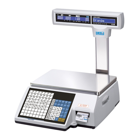
CL5000-Series
Advertisement
Table of Contents

Related Manuals for CAS CL5000 Series


Summary of Contents for CAS CL5000 Series
- Page 1 CAS (USA) Corporation 99 Murray Hill Parkway East Rutherford, NJ 07073 01/19/2008 CL5000-Series Installation for Lantronix Internal Ethernet 1. The internal Ethernet installation kit will contain an Ethernet I/O board, internal Ethernet board, crossover Ethernet cable, power and indicator lights cable, and the necessary hardware.
- Page 2 3. Remove the dummy cover from the bottom of the scale. 4. Plug the Ethernet cable and the power/indicator light cable onto the Ethernet I/O board. 5. Install the Ethernet I/O board into the hole where the dummy plate was removed threading the cables up into the scale.
- Page 3 6. If standoffs are not installed on the main board at the locations indicated by the arrows then remove the main board and install the standoffs using the nuts and standoffs that are part of the hardware package. 7. Plug the internal Ethernet board into J3, the grey connector. Secure the board with two Philips head screws included in the hardware package.
- Page 4 8. Thread the cables from the Ethernet I/O board to the internal Ethernet board. Make sure to run the cables under the load cell support bracket as shown in the picture. When done reassemble the scale.
Need help?
Do you have a question about the CL5000 Series and is the answer not in the manual?
Questions and answers