Table of Contents
Advertisement
Quick Links
Advertisement
Table of Contents

Related Manuals for CAS CL5500


Summary of Contents for CAS CL5500
- Page 1 CL5000 Series (CL5000, CL5500) Service Manual (English) Rev. 2011. 04. 07...
-
Page 2: Table Of Contents
Table of Contents 1. Proper Operation ..............................5 1.1 Introduction..............................5 Model and Specificationl ........................6 1.3 Environmental Conditions & Safety .......................7 1.4 Leveling and Footer Location .........................8 1.5 Power Outlet and Requirements ......................11 2. Classification ..............................13 2.1 Scale Overview ............................. 13 2.2 Display and Indicators .......................... - Page 3 6.2 Installing Wireless Lan Card ........................ 74 6.3 Installing Memory Expension Card ..................... 74 7. Update ................................75 7.1 F/W update (CL5000) ........................... 75 7.2 F/W update (CL5500) ........................... 77 8. Schematic & Diagrams ..........................78 8.1.1 System Block Diagram (CL5000-B,P,R,G,S,H) ................78...
- Page 4 8.1.2 System Block Diagram (CL5500-D) ....................79 8.2.1 Connection Diagram (CL5000-B,P,R,G,S,H)..................81 8.2.1 Connection Diagram (CL5500-D)..................... 82 8.3 I/O Pin Connection (CL5000-B,P,R,G,S,H) ..................84 I/O Pin Connection (CL5500-D) ....................85 9. Exploded Views .................. 오류! 책갈피가 정의되어 있지 않습니다. 9.1 Scale Assy (B,P,R,G-type) ............오류! 책갈피가 정의되어 있지 않습니다.
-
Page 5: Proper Operation
Thank you for purchasing the CAS CL5000 series price computing printer scale. We have designed this equipment with advanced features, high quality construction, and user-friendly menu driven programming. We are confident that you will find the CAS CL5000 series scale will meet all of your most demanding needs. -
Page 6: Model And Specificationl
-2.999Kg -5.998Kg -9.995Kg -5.998lb -9.995lb -29.99lb B,P,R,S,H-Type 24 digit VFD + Graphic LCD (CL5000 Series) 24 digit LCD + Graphic LCD (CL5500 Series) G-Type Graphic LCD Display D-Type 25 digit LCD + Graphic LCD Tare: 4 digit Weight: 5 digit... -
Page 7: Environmental Conditions & Safety
1.3 Environmental Conditions & Safety 1) Please avoid the following hostile conditions Temperatures below or exceeding: Ungrounded electrical outlet -10° C ~ 40° C (14° F ~ 104° F) Excessive vibration Unstable or flimsy surface Wind or fans functioning in direct Shared electrical outlet ... -
Page 8: Leveling And Footer Location
1.1) General Footer Factory setting (Footer location is following picture) CL5000 / CL5500 Series CL5500-D... - Page 9 1.2) Short Case Footer Unscrow the footer and place in center hole for narrow place. 2) Leveling If the scale is not properly leveled, please adjust the 4 adjustable legs at the bottom of the scale. Turn the legs clockwise or counterclockwise so as to center the bubble of the leveling gauge inside the indicated circle.
-
Page 11: Power Outlet And Requirements
Power Outlet and Requirements Power Source : AC 100~240V, 50/60Hz, 1.5A Power consumption : Max 90W CL5000 / CL5500 series’s outlet is on bottom of scale. RS232C Power Outlet Power Switch CL5500-D... - Page 12 3) Do not use any 3-prong to 2-prong adapters or break-off the third prong from the CLP power cord. The third prong is necessary and must be properly connected. If you have any problems or questions regarding this matter, make sure to contact the CAS Service Department.
-
Page 13: Classification
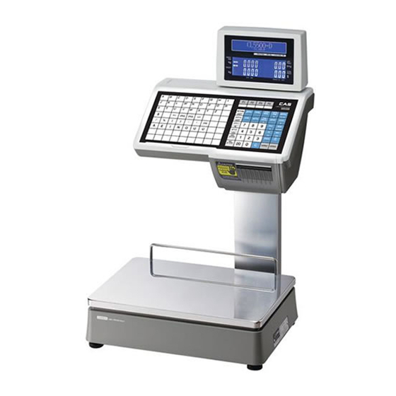
2. Classification 2.1 Scale Overview CL5000/CL5500 has 4 differrnt type Standard Type, Pole Type(R,P), Hanging Type, Double body Type. ■ Standard Type ■ Pole Type P ■ Pole Type R ■ Hanging Type H... - Page 14 ■ Pole Type G ■ Self-service Type ■ Double body Type (CL5500 ONLY)
-
Page 15: Display And Indicators
There is VFD, LCD(202x64) display on CL5000. VFD display indicates program tare, weight, unit price, total price. Underbar inicates stable, net, zero, auto, save, prepack, D/C, shift, data transfer. LCD display shows menu massages for program mode. ■ Type-I: 5/8/9 ■ Type-II : 4/5/6/6 - CL5000 - CL5500... - Page 16 ■ TYPE-III : CL5000-G ■ TYPE-Ⅳ : CL5500-D...
-
Page 17: Printer
Discount status indicator SHIFT Speed key shift status indicator Data transmission status indicator Master status indicator Slave status indicator LN (CL5500) Ethernet Connection Status 2.3 Printer •Cartridge type print mechanism •High quality ROHM printer head (50km/5x10 7 pulses) •Improved a rotating force by using 2 independent motors •Large compartment for 120mm... - Page 18 CL5000-H...
- Page 19 CL5500-D...
-
Page 20: Commuication
2.4 Commuication < CL5000 Series > ■ Standard ① RS232 ② P/S 2 ③ Cash Drawer ■ Options ④ Ethernet cartrige ⑤ Wireless Ethernet cartrige ③ Cash Drawer ② P/S 2 ① RS232 ④ Ethernet Module ⑤ Wireless Ethernet Module... - Page 21 <CL5500 Series> ■ Standard ① RS232 ② P/S 2 ③ Cash Drawer ④ Ethernet ⑤ USB (Virtual COM) ■ Options ⑥ Wireless Ethernet Module CL5500 – B,P,R,S CL5000 -D...
-
Page 22: Key Pad
2.5 Key Pad Key pad is like following picture (This may change depands on contury) ■ Standard Type Keypad ■ Pole Type Keypad ■ Hanging Type Keypad... - Page 23 Key pad is like following picture (This may change depands on contury) ■ Self-service Type Keypad ■ Doubody Type Keypad. * Hot key and Undifine key setting reference Menu code 1880...
-
Page 24: Getting Started
3. Getting Started 3.1 Sealing Method 3.2 Installation of the Label Roll ■ Label Specifications Outer diameter of roll : 100mm Inner diameter of roll : 40mm Width of receipt roll : 40, 50, 60mm Width of label roll : 60mm(MAX) ■... - Page 25 To install the label roll at ANY time you must follow the directions in this section: 1) Press the ON/OFF key and make sure that the display is completely off. Open the printer’ s side- access panel. (See fig.1) CL5000 / CL5500 CL5500-D 2) Lift up TPH lever as fig 2...
- Page 26 5) Place the label in the scale as fig. 5 CL5000 / CL5500 CL5500-D 6) Press the FEED key. NOTE: For auto label calibration press FEED key two or three times * If label position is not correct, you have to check the followings: a.
-
Page 27: Turning Power On/Off
3.3 Turning Power On/Off When you turn on scale, display will show 9 ~ 0 for self testing. PROGRAM MODE (1/3) 1. PLU 9999 999999 99999999 2. PLU Data Table I. 3. PLU Data Table II. During each number and buzzer sound is processing following procedure. Buzzer On Initial Port,Timer,UART(AD),CPLD,PrinterDriver,RTC Printer Driver Start Start Timer... -
Page 28: Program Menu And Tree
3.4 Program Menu and Tree 3.4.1 How to access PROGRAM MODE You can see the Program Menu screen by pressing the MENU key. The 2 numbers at top left (1/3) indicate the number of pages or screens. The number to the left of the slash is the current page or screen number and the number to the right of the slash indicates the total number of pages or screens. -
Page 29: Program Menu Tree
3.4.2 Program Menu Tree CODE Menu CODE Sub Menu CODE Sub Menu 1100 1110 Change Price 1120 New/Edit 1120 1130 Discount 1131 New/Edit 1132 List 1133 Delete 1137 Delete by PLU(DC) 1138 Delete by Dept(DC) 1139 Delete All 1140 Management 1141 Copy 1142... - Page 30 1600 Report 1610 X1 Report 1611 Scale 1612 1613 Misc. PLU 1614 Group 1615 Department 1616 Hourly 1617 Clerk 1620 Z1 Report 1630 X2 Report 1631 Scale 1632 1633 Misc. PLU 1634 Group 1635 Department 1636 Hourly 1637 Clerk 1640 Z2 Report 1650 Clear All...
-
Page 31: Calibration Menu Tree
1900 Communication 1910 Network Setting 1911 Service Type 1912 DHCP 1913 1914 Remote IP 1915 RS232C 1916 WLAN Setting 1917 WLAN Config 1920 Application 1930 Scale Lock/Unlock 1940 Check Scale 1950 Backup to scale 3.4.3 Calibration Menu Tree CODE Menu CODE Sub Menu CODE... -
Page 32: Calibration Mode
4.1 Calibration (Calibration MENU -> 1. Calibration) Execute Weight Calibration and A/D related settings (Access Authorized CAS Tester only) Open the tray and remove the calibration sealing. (CAUATION: Lift the tray Right side first and unlock the left side) Order to access calibration mode: Insert a stick into the CAL switch. - Page 33 CL5500-D...
-
Page 34: Span Calibration (Menu Code 8110)
First page of Calibration mode CALIBRATION MODE (1/2) 1. Calibration 8000 ModE 2. System Options 3. Printer Hardware 4.1.1 Span Calibration (Menu Code 8110) (Calibration MENU -> 1. Calibration -> 1. Span Calibration) *Requires set of certified weights. (For best result prepare 15kg/6kg (max) weights) Display shows the amount of weight that you will need. - Page 35 Display shows “Wait4” ~ “Wait0” then following message CALIBRATION (1/3) 1. Span Calibration 8100 ModE 2. Span/Zero Fine Adjust 3. Capacity & Units Error Message * When tray is unstable during calibration process, following message appear. Cal Error – Unstable (0x01) WAit0 2776 2776...
-
Page 36: Span/Zero Fine Adjust (Menu Code 8120)
4.1.2 Span/Zero Fine Adjust (Menu Code 8120) (Calibration MENU -> 1. Calibration -> 2. Span/Zero Fine Adjust) This mode is for fine tuning of scale after span Cal. Please put Max weight on the tray and adjust ▶ A/D results at 60000, using the cursor key “◀ .”... - Page 37 * Insert setting value by number key pad - Set Span value: use curser key to highlight span value. - Type estimate value using number key then press “TEST” key for results # This process may take several times to set 60000. During this process Max Capacity weight is needed for best result.
-
Page 38: Capacity & Units (Menu Code 8130)
4.1.3 Capacity & Units (Menu Code 8130) (Calibration MENU -> 1. Calibration -> 3. Capacity & Units) Set scale’s Weighing unit, capacity, Interval, Cal Unit. Caution: Span calibration must take place after “Capacity & Units” setting. Do not change setting after Span calibration. Option Setting Value Weighing Unit... -
Page 39: Gravity Constant (Menu Code 8140)
4.1.4 Gravity Constant (Menu Code 8140) (Calibration MENU -> 1. Calibration -> 4. Gravity Constant) CL-5000 scale enables to calibrate in any country. You can set according to country standard gravity constant data. For case of full recalibration set the factory gravity first and then local area gravity code. -
Page 40: Percent Calibration (Menu Code 8150)
Hungary Budapest 9.8069 Chicago 9.8024 Indonesia Djakarta 9.7814 Dallas 9.7949 Iraq Baghdad 9.7964 Detroit 9.8039 Japan Mishima 9.7979 Los Angeles 9.7979 Korea Seoul 9.7994 New York 9.8024 Kuwait Kuwait 9.7919 Philadelphia 9.8024 Lebanon Beirut 9.7964 San Francisco 9.7994 Mauritius Port Louis 9.7859 Venezuela Caracas... -
Page 41: Linearity Adjust (Menu Code 8160)
4.1.6 Linearity Adjust (Menu Code 8160) (Calibration MENU -> 1. Calibration -> 6. Linearity Adjust) You can re-adjust the med-range weight level for precise calibration. ZERO CALIBRATION (1/3) - Remove all weight. ULoAd 10731 10731 - Press PRINT when ready. ①... -
Page 42: Zero & Tare Setting (Menu Code 8170)
4.1.7 Zero & Tare Setting (Menu Code 8170) (Calibration MENU -> 1. Calibration -> 7. Zero & Tare Setting) CAUTION: This Setting is part of (OIML, NTEP, etc) regulation must be setting by the local restriction. You can set the ZERO, TARE at acceptable range and maximum display range. ZERO &... -
Page 43: Factory Setting (Menu Code 8180)
④ Overload Range(d) You can set the maximum overload range. For example, [9] set as 15.045g (5gx[9]=45g). If the weight is over 15.045 overload message will appear. ⑤ Accumulation(Y/N) You can set Tare weights additively. This is useful additional package is used for different goods. ⑥... -
Page 44: Linearity Fine Adjust (Menu Code 8184)
4.2.4 Linearity Fine Adjust (Menu Code 8184) (Calibration MENU -> 1. Calibration -> 8. Factory Setting -> 4. Linearity Fine Adjust) ① Selecting“LinearityFineAdjust” LINEARITY FINE ADJUST (1/1) Zero:[ 10730] 8184 Mid :[ 36532] Span:[ 88145] ⓐ Menu Code ⓑ Internal value ⓒ... -
Page 45: Hysteresys Calibration (Menu Code 8185)
4.2.5 Hysteresys Calibration (Menu Code 8185) (Calibration MENU -> 1. Calibration -> 8. Factory Setting -> 5. Hysteresys Calibration) ①Selecting “Hysteresys Calibration” HYSTERESYS CALIBRATION (1/1) USE WEIGHT :[ 2] kg 8185 ModE Full Capa Weight : 6.000 kg ② For 2kg Mid-weight, input “2”key and press “print” ZERO CALIBRATION (1/4) - Remove all weight. - Page 46 ⑦ Put on the Weight for Max. Capacities then press “PRINT” *Menu 8130 sets the max capacity for calibration. SPAN CALIBRATION (3/4) - Place 6.000 kg on the platter. WAit4 83752 111522 - Press PRINT when ready. ⑧ While calibrating span display shows “Wait4” ~ “Wait0” and follow next message for Mid Calibration.
-
Page 47: Memory Clear
4.3 Memory Clear (Calibration MENU -> 2. System Options -> 1. Clear Memory) You can clear memory depends on options below. CLEAR MEMORY (1/2) 1. Clear Report 8210 ModE 2. Clear All PLU 3. Clear All Table CLEAR MEMORY (2/2) 4. -
Page 48: Scale Type
Menu Code 8220 (Calibration MENU -> 2. System Options -> 2. Scale Type) Select model: Basic type (CL5000-B), pole type, (CL5000-R, P, G), hanging type (CL5000-H), Self-service type(CL5000-S), Double-body type(CL5500-D) CAUTION: Selecting wrong model code will effect on key function. -
Page 49: Printer Hardware
4.5 Printer Hardware Sub-menus Description Select label, ticket, continuous label mode. Print Mode Lable mode: “Width(60)”, “Height(40)” and “Gap length(2)” Label / Ticket Ticket mode: “Width(60)”, “Feed(20)” and “End Margin(5)” Size Continous Label: “Width(60)”, “Feed(40)” and “End Margin(2)” * ( ) are default value. Sensor Enter the “Gap(128)”... -
Page 50: Sensor Calibration (Menu Code 8330)
4.5.3 Sensor Calibration (Menu Code 8330) (Calibration MENU -> 3. Printer Hardware -> 3. Sensor Calibration) You can input “Gap,” “Peel,” “Out of Paper” manually. “TEST” key will automatically feed the label several times to calculate the measurement. * For Ticket mode display will be same except “Gap” value. (This value will not save) 4.5.4 Sensor &... -
Page 51: Network Options
4.6 Network Options 5.6.1 Enable Interface (Menu Code 8410) (Calibration MENU -> 4. Network Options -> 1. Enable Interface) You can set usage of I/O interface.(CL5000) ENABLE INTERFACE (1/2) Ethernet(TCP/IP) :[Y] 8410 ModE :[N] RS485 :[N] ENABLE INTERFACE (2/2) PS/2 :[Y] 4.7 Self Test 4.7.1 Display Test (Menu Code 8510) -
Page 52: Keyboard Test (Menu Code 8530)
4.7.3 Keyboard Test (Menu Code 8530) (Calibration MENU -> 5. Self Test -> 3. Keyboard Test) You can test keyboard by pressing. KEYBOARD TEST (1/1) Raw Code:[006C] Menu Key Flag::[0] 8530 ModE Cnv.Code:[0003] Mode:[1] KEYBOARD TEST (1/1) Raw Code:[006C] Menu Key Flag:[0] Cnv.Code:[0003] Mode:[1] [ESC]=Exit,[PRINT]=Mode Change KEYBOARD TEST... -
Page 53: Chess Print (Menu Code 8540)
1. The rubber roller may be dirty or have something stuck to it. Also, the roller may be perforated. 2. This is a clear indication that the TPH has been damaged or burned out. If you need to replace the TPH, please contact the CAS Service Department. 4.7.5 Printer Sensor Test (Menu Code 8550) (Calibration MENU ->... -
Page 54: Memory Information (Menu Code 8560)
Test Items Description Peel-off Cheek Peel-off senor stops label Head-up Cheek TPH head is open or not Cheek label’s gap Peel Peel-off sensor value 4.7.6 Memory Information (Menu Code 8560) (Calibration MENU -> 5. Self Test -> 6. Memory Information) You can install expansion memory-pack up to 6MB Current memory show as O unused memory as X (each 0 is 1MB). -
Page 55: Servicing & Parts Replacement
5. Servicing & Parts Replacement... -
Page 57: Platform Safety Overload Adjustment
5.1 Platform Safety Overload Adjustment 1) Turn power off and remove power cord 2) Remove tray from scale (make sure lift right side first and unlock the left hook) CL5500-D 1) Turn power off and remove power cord 2) Remove tray from scale... - Page 58 3) Remove calibration cealing 4) Remove the upper case 5) Put 150% of max weight on platform rear right. This point Allen-bolt should not be touched 6) Adjust Allen-bolt just about to touch the bottom frame 7) Contiune the procedure on each corner B,P,R,G-type H-type D-Type...
-
Page 59: Removing The Upper Case
5.2 Removing the Upper Case 1) Turn power off and remove power cord 2) Remove tray from scale (make sure lift right side first and unlock the left hook) 3) Remove printer cartridge 4) Remove 6 bolt from bottom case(for pole type: remove pole mount bolt first) For hanging type: remove 3 bolt from front cover 5) Remove 4bolt from upper case... - Page 60 6) Remove keybord and display cable to remove upper case B,P,R,G type: * Carefull with front key pad connector H type: * Open up front cover from printer part. NOTE: Assemble hook part first. Remove front cover bolt (2 bolt) Open up from printer side to disassamble front cover...
- Page 61 CL5500-D 1) Remove head cover bolt (4 bolt) 2) Open up from printer side to disassamble head cover...
-
Page 62: Main Board Replacement
5.3 Main board Replacement 1) Turn power off and remove power cord 2) Remove following cables SMPS Line Key Board Line Display Board Line Printer Board Line A/D Board Line 3) Remove following bolt to remove main board B,P,R,G type: Connector locations H type: 1. -
Page 63: Power Supply Replacement
CL5500-D 1) Remove bolt & open up head cover 2) Remove all cable & bolt 3) Replace main board 5.4 Power Supply Replacement - CL5000 1) Turn power off and remove power cord 2) Remove upper case(following 6.2) 3) Remove power lines (white cables) - Page 64 5) Full forward power module and remove power cables on SMPS 6) Disassamble support frame and remove side bolt(4) to remove power supply. - CL5500 1) Turn power off and remove power cord 2) Remove upper case(following 6.2) 3) Remove power line...
- Page 65 - CL5500-D 1) Turn power off and remove power cord 3) Remove upper platform 2) Remove upper case 3) Remove SMPS Protect cover & bolt 4) remove power supply(SMPS)
-
Page 66: Load Cell & Ad Converter Replacement
5.5 Load Cell & AD Converter Replacement - CL5000 1) Turn power off and remove power cord 2) Remove upper case(6.2) 3) Remove upper frame(Load cell moult)bolt Lodecell suspansion bolt 4) Remove bottom frame bolt NOTE: Carefull with load cell this procedure may cause critical damage on scale A/D mounting bolt L/C Line A/D connetor... - Page 67 - CL5500 1) Turn power off and remove power cord 2) Remove upper case(6.2) 3) Remove upper frame(Load cell moult)bolt 4) Remove bottom frame bolt NOTE: Carefull with load cell this procedure may cause critical damage on scale 5) Remove A/D module bolt(3) and cable(A/D data line, L/C line)
- Page 68 - CL5500-D 1) Turn power off and remove power cord 2) Remove Seal bolt (2 ea) 3) Remove upper case 4) Remove sealing cover bolt 5) Remove bottom plate bolt (2ea) NOTE: Carefull with load cell this procedure may cause critical damage on scale...
-
Page 69: Print Assembly Replacement
5.6 Print Assembly Replacement 1) Turn power off and remove power cord 2) Remove printer cartridge 3) Remove upper case(6.2) 4) Remove printer connecting bolt (H type) NOTE: You must remove center collom first Printer mounting bolt (B,P,R,G type) D -type Remove printer module (lift upper right side first) Reference following exploed view... -
Page 70: Display Replacement
3) Remove keyboard and display cable of main board Key_Board Cable Display Cable CL5000 CL5500 4) Remove front display board B,P,R type: lift display board at arrow side Remove rear display board by lifting bottom part to unlock 5) Remove Front, Rear display by unhook support part. -
Page 71: Keyboard Replacement A,B(With/Without Breaking Sealing)
CL5500-D 1) Remove display case by unhook support part (head + display case) 2) Both are divided into separate (Display case) 3) Remove cable & bolt 5.8 Keyboard Replacement A,B(with/without breaking sealing) A: with break sealing 1) Turn power off and remove power cord 2) Remove upper case(6.2) - Page 72 6) Connect keyboard cable by pushing keyboard suspend lock / add metal support plate 7) Stick the keyboard pad H-type -Remove keypad cover and metal dome cover CL5500-D 1) Remove headcover bolt (4 bolt) (5.2) 2) Open up from printer side to disassemble (5.2) 3) Remove keypad from headcover...
-
Page 73: Installing Options
6. Installing Options Additional expansion memory and network card is available for ungrade 6.1 Installing Ethernet Card 1) Turn power off and remove power cord 2) Remove Ethernet card cover 3) Insert Ethernet card onto slot (use same slot for wireless module) Ethernet card B, P, R, G type H type... -
Page 74: Installing Wireless Lan Card
6.2 Installing Wireless Lan Card 1) Turn power off and remove power cord 2) Remove Ethernet card cover 3) Insert Wireless LAN Card. Insert local wireless CF card 4) Turn on power when installation is finished 6.3 Installing Memory Expension Card (CL5000) 5) Turn power off and remove power cord 6) Remove Upper Case 7) Insert Memory Expension Card. -
Page 75: Update
7. Update 7.1 F/W update (CL5000) NOTE: While you are turning on the scale, you must PUSH CAL botton. If you didn’t follow this procedure, scale will not accept any signal from PC. Step1: Connect RS232C to computer Pin-layout is following diagram Scale(DB-9 Female) PC (DB-9 Male) (2) -------------------------------- (3) - Page 76 Step6: Turn on the scale while CAL botton is pushed. (at this point display will show “RDY”) NOTE: If CAL botton isn’t pushed, scale will not accept any signal from PC. After few second download process will occure When download finish scale will reboot NOTE: During this procedure power or communication connector is cut off You must redo from step1...
-
Page 77: F/W Update (Cl5500)
(5) -------------------------------- (5) Step2: Play IM Updater.exe Step2: Select RS232C communication port by pressing Step3: Select Baud Rate ‘115200’ Step4: Select Target Model ‘CL5500 F/W’ Step5: Select new firmware ROM pressing Step6: Press , ready to F/W –ROM download * Software will not download if the firmware version is old or file desination is wrong... -
Page 78: Schematic & Diagrams
8. Schematic & Diagrams 8.1.1 System Block Diagram (CL5000-B,P,R,G,S,H) - Page 79 8.1.2 System Block Diagram (CL5500-D)
- Page 80 8.1.3 System Block Diagram (CL5500-B,P,R,H,S)
- Page 81 8.2.1 Connection Diagram (CL5000-B,P,R,G,S,H)
- Page 82 8.2.2 Connection Diagram (CL5500-D)
- Page 83 8.2.3 Connection Diagram (CL5500-BPRHS)
- Page 84 8.3 I/O Pin Connection (CL5000-B,P,R,G,S,H)
- Page 85 I/O Pin Connection (CL5500)
- Page 86 9. Exploded Views 9.1 Double Body Type – (Head cover A’ssy)
- Page 87 9.2 Double Body Type – (Cartridge A’ssy)
- Page 88 9.3 Double Body Type – (Base bracket A’ssy)
- Page 89 9.4 Double Body Type – (Door A’ssy)
- Page 90 9.5 Double Body Type – (Head A’ssy)
- Page 91 9.6 Double Body Type – (Tray A’ssy)
- Page 92 9.7 Double Body Type – (Upper A’ssy)
- Page 93 9.8 Double Body Type – (Platform A’ssy)
- Page 94 9.9 Double Body Type – (Body A’ssy)
- Page 95 9.10 Lan card...
- Page 96 10. Part List 10.1 Electronic 10.1.1 CL5500-D Image Part Code Parts Name DESCRIPTION Q'ty MAIN PCB ASS'Y AD PCB PRINTER PCB IO PCB WLAN MODULE DISPLAY PCB...
- Page 97 10.1.2 CL5500-BPRHS Image Part Code Parts Name DESCRIPTION Q'ty MAIN PCB ASS'Y AD PCB PRINTER PCB IO PCB WLAN MODULE B TYPE DISPLAY PCB...
- Page 98 Image Part Code Parts Name DESCRIPTION Q'ty P TYPE FRONT DISPLAY PCB P TYPE REAR DISPLAY PCB R TYPE FRONT DISPLAY PCB R TYPE REAR DISPLAY PCB SELF KEY PCB...
- Page 99 10.1.3 CL5500 COMMONE SMPS TPH ASS'Y 7612S0000042 AC SOCKET CONNECTOR JR-101(POSCALE,SWITCH 미포함) 6830F0001300 NOISE FILTER SN-M3H-CM(LP)
- Page 101 2-1. DISPLAY CASE ASS'Y IMAGE Part Code Parts Name DESCRIPTION Unit Q'ty 1030A0002260 DOOR PLATE CL5000 23*16.5 1510A0003080 SCREW-TAPPING(PH)-1 M3*8(CHINA) 2050A0006530 DISPLAY COVER CL5500-D 양면공용 (TOOL) 2004A000163A HEAD COVER CL5500-D 350*22.5*113.9 2100A0002450 MEMBRANE S/W CL5500-D 319.6*151*1.5 2004A0001650 DISPLAY CASE CL5500-D 193*150.5*57...
- Page 102 2-2. BASE BRACKET ASS'Y IMAGE Part Code Parts Name DESCRIPTION Unit Q'ty 1030A0004360 LEVER OPEN CL5000-D 47.5*14.5*1.5 1000A000269A MAIN BRACKET 59*49.5*35*9t(CL-J,MADE IN KOR 1000A0002700 BRACKET PRESSURE 51*54.6*9(CL-J,MADE IN KOREA) 1000A0002710 TPH BKT HOLDER 57*47.2*21(CL-J,MADE IN KOREA) 1030A0004400 LOWER FRAME COVER CL5000-D 38.7*17.8*1t 1030A000434A MECHANISM BRACKET...
- Page 103 1150A000028A LOWER FRAME CL5000-D 77*47.5*22.5 1210A0000940 SHAFT BEARING CL5000 @7*37 1210A0000950 SHAFT BUSHING CL5000JR @8*@12*5.9 1210A0000960 CL5000JR @4*12.4(SUS304) 1210A0001030 MAIN BRACKET SHAFT CL5000JR ø5*62.7(SUS303) 1210A0001040 OPEN LEVER SHAFT CL5000JR ø6*69.3(SUS303) 1501A0003060 SCREW-MACHINE(FH) M3*6...
- Page 104 1502A0002100 SCREW-MACHINE(PH) M2*10 1502A0003060 SCREW-MACHINE(PH) M3*6 1502A0003200 SCREW-MACHINE(PH) M3*20 1502MSU03040 SCREW-MACHINE(PH) M3*4-SUS 1503A0004120 SCREW-MACHINE(WPH) M4*12 1530MSU06100 BOLT-WRENCH M6*10-SUS 1502A0004120 SCREW-MACHINE(PH) M4*12...
- Page 105 1540A0002000 NUT(HEX) M2*0.4 1550A0002040 WASHER(FLAT) ø2 1550MSU03050 WASHER(FLAT) ø3*ø6*0.5-SUS 1551A0003000 WASHER(SPR) ø3 1561MSU03000 E-RING ø3*ø7*0.6-SUS(CHINA) 1561MSU04000 E-RING ø4*ø9*0.6-SUS 1590A0000090 OPEN LEVER SPRING ø06*ø9*199(LP) -외주...
- Page 106 1590A0000410 BRACKET PRESSURE SPRING CL5000JR 7.2*1*35 1590A0000420 TPH BKT SPRING CL5000 JR @1*10*27 2007A0000030 GEAR BOX CL5000-J 34*55.2*15.4 2007A0000040 GEAR BOX COVER CL5000-J 34.6*31.6*2t 2011A0000110 REWIND SHAFT CL5000 13*13*25 2011A0000130 BUSHING BEARING CL5000 ø28*15.5 2011A000016A SPUR GEAR CL5000 OD_21.5*M_0.5...
- Page 107 2011A000017A SPUR GEAR CL5000 OD_29.4*M_0.5 2011A000018B SPUR GEAR CL5000J OD_19.5 M_0.5 2620A000030A SHAFT SILICON RUBBER CL5000J @15*@4*90.7 6191PCL01010 PCB-CONTROLLER 6191-PCL-0101-0(CL5000J TPH) 6450TMT0003B PM MOTOR 42P048L0-00802(MOONS')CL5000 7600S000302A LIMIT S/W DF-03S-7P-Z(CL5000J)
- Page 108 2-3. HEAD ASS'Y IMAGE Part Code Parts Name DESCRIPTION Unit Q'ty 1030A0004350 HEAD SUPPORT CL5500-D 227*110*138 1030A0004380 PAPPER CUTTER CL5500-D 85.5*4.5*0.5t 1150A000027A POST PIPE CL5500-D 100*44*215 1210A0001080 FIXING NUT CL5500-D M6*39 1502A0003060 SCREW-MACHINE(PH) M3*6 1502A0006120 SCREW-MACHINE(PH) M6*12 1510A0003080 SCREW-TAPPING(PH)-1 M3*8(CHINA)
- Page 109 1510A0004080 SCREW-TAPPING(PH)-1 M4*8(CHINA) 1510A0004120 SCREW-TAPPING(PH)-1 M4*12 1511A0004160 SCREW-TAPPING(FH)-2 M4*16 1513MPN04120 SCREW-TAPPING(WPH) M4*12-NI(1종) 1515A0003080 SCREW-TAPPING(FH)-1 M3*8 2004A000162A HEAD CL5500-D 337*278*244 2050A0006540 DECO PLATE CL5500-D 290 * 24 *1t...
- Page 110 2-4. CARTRIDGE ASS'Y IMAGE Part Code Parts Name DESCRIPTION Unit Q'ty 2004A000166A CARTRIDGE CL5500-D 190*183*88 2010A000028B REWIND PAPER LOCKER CL5000 @29.5*83.8*19.1 2004A000167A ROLL COVER CL5500-D 107*122.5*10 2011A0000120 REWIND GUIDE CL5000 @42*71 2620A0000290 SILICONE WASHER CL5000 @17*1.5 2004A0000920 REWIND PAPER CLP @33.5*69...
- Page 111 2004A000091A ROLL PAPER FEED CLP @@35.3*83.2 (유상) 1070A0000030 MAGNET CLP @15 x 3 1590A000039A PRESSURE COIL SPRING CL5000 @18*@13.5*44 (유상) 1510A0004100 TAPPING SCREW (PH)-1 M4*10 1510A0004120 TAPPING SCREW (PH)-1 M4*12 1000A0002170 REWIND STOPER PLATE CL5000 @53*0.5t 9010A0000150 LABEL STICKER CL5000 @58*40(400매;영문)
- Page 112 2-5. DOOR ASS'Y IMAGE Part Code Parts Name DESCRIPTION Unit Q'ty 1070A0000060 MAGNET CL5500-D @10 X 4t NDH 1210A0001070 DOOR SHAFT CL5500-D @1.5*120 1515A0003080 SCREW-TAPPING(FH)-1 M3*8 2004A000164A DOOR CL5500-D 183*221*22.1...
- Page 113 2-6. TRAY ASS'Y IMAGE Part Code Parts Name DESCRIPTION Unit Q'ty 1000A000086A TRAY POLE FENCE ø6*290*40)LP-Ⅱ 1000A0003270 TRAY CL5500-D 400*330*25(LARGE) 1000A0003260 TRAY CL5500-D 380*270*15*1T 1540A0004000 NUT(HEX) M4*0.7 1551MSU04000 WASHER(SPR) ø4*ø6.9*1-SUS...
- Page 114 2-7. UPPER CASE ASS'Y IMAGE Part Code Parts Name DESCRIPTION Unit Q'ty 2004A0001590 UPPER CASE CL5500-D 395*285*85 2010A0000260 WATER LEVEL GAGE COVER GAGE COVER(POSCALE) 1505A0004100 SCREW-MACHINE(TH) M4*10 9020A0000090 STICKER S-2000(ON/OFF) 1563A0003060 RIVET @3.2*6 (CL5000-HS 전용) 1810CL000332 SPEC PLATE CL5000 (영공), ENGLISH...
- Page 115 2-8. PLATFORM ASS'Y IMAGE Part Code Parts Name DESCRIPTION Unit Q'ty 1030A0004450 AD BRACKET CL5500-D 39*11*9 1100A0001110 UPPER PLATFORM CL5500-D 336.5*240*24X 1100A000112C LOWER PLATFORM CL5500-D 168*80*68X 1261A0000080 BOLT-LIMIT M5*0.8*8.5(Zn황색,15K)(AP)유상 1502A0003040 SCREW-MACHINE(PH) M3*4 1503MPN03100 SCREW-MACHINE(WPH) M3*10-NI 1532MSU06250 BOLT-WRENCH(ST) M6*25-SUS...
- Page 116 1535MSU05120 BOLT-WRENCH(WA) M5*12-SUS 1535MSU06200 BOLT-WRENCH(WA) M6*20-SUS 2600A0001030 PLATFORM RUBBER CL5500-D Ø20*20...
- Page 117 2-9. LOWER BODY ASS'Y IMAGE Part Code Parts Name DESCRIPTION Unit Q'ty 1030A0004430 WEIGHT BALANCE CL5500-D 205*80*10 1030A0004440 IO COVER CL5500-D 197*42*24 1030A0004460 SMPS COVER CL5500-D 80*52.7*46.6 1030A0004470 INLET COVER CL5500-D 50*40*25 1100A0000990 BODY CL5500-D 389*279*68 1100A0001130 SUPPORT CL5500-D 113*112.5*58.5X...
- Page 118 1502A0004200 SCREW-MACHINE(PH) M4*20 1502A0005250 SCREW-MACHINE(PH) M5*25 1503A0004080 SCREW-MACHINE(WPH) M4*8 1507A0003070 BOLT-CONNECTOR M3*7(H)*6(D)-CL5500 1512A0004120 SCREW-TAPPING(PH)-2 M4*12 1535MSU05120 BOLT-WRENCH(WA) M5*12-SUS 1550MSU06180 WASHER(FLAT) ø6*ø18*1.6-SUS...
- Page 119 2004A0001600 SUPPORT COVER CL5500-D 92*123*48 2004A0001610 SUPPORT CABLE COVER CL5500-D 86.5*113*19.5 2010A0000260 WATER LEVEL GAGE COVER GAGE COVER(POSCALE) 2022A0000041 WATER LEVEL GAGE ø14.9*8(S-2000)상보 2610A000009B FOOT NBR M8*1.25*35(비도전성)절연 7642A0000020 RETAINER COIL LC-2 Ø4.2*Ø9*2.6W*50L(CL-D)
- Page 120 2-10. C/T BOX ASS'Y IMAGE Part Code Parts Name DESCRIPTION Unit Q'ty 9100CL601330 C/T BOX CL5500-D 9107A0000050 C/T PAD CL5500-D 750*450 9207A0000040 STYROFOAM BOX CL5500-D 750*450*330(RIGHT) 9207A0000050 STYROFOAM BOX CL5500-D 750*450*330(LEFT) 9300A0000020 POLY BAG 90*150*0.05T(FUSE) 9300A000003A POLY BAG 230*330*0.05T(MANUAL) 9307A000003B POLY BAG 700*750*0.04T(SET,HD)
- Page 121 9400A0000460 SILICAGEL 2-11. SEALING ASS'Y(OUTER) IMAGE Part Code Parts Name DESCRIPTION Unit Q'ty 2004A0001700 CAL COVER CL5500-D 54.4*43.5 1265A0000010 BOLT SEALING M3*9(황동,HEAD 3mm포함) 9900A0000020 SEALING WIRE 300M/ROLL 1507A0003170 BOLT-CONNECTOR M3*17(LP-Ⅱ)
- Page 122 2-12. SEALING ASS'Y(STICKER) IMAGE Part Code Parts Name DESCRIPTION Unit Q'ty 2004A0001700 CAL COVER CL5500-D 54.4*43.5 1507A0003170 BOLT-CONNECTOR M3*17(LP-Ⅱ) 9020OML00010 STICKER 유럽 CAL,봉인지...
- Page 123 2-13. SEALING ASS'Y(INNER) IMAGE Part Code Parts Name DESCRIPTION Unit Q'ty 1030A0004410 LOADCELL CASE CL5500-D 68.5*65.5*33 1030A0004420 AD CASE CL5500-D 64*60.5*32 1265A000031A BOLT-SEALING M3*26(NT-200, 201A)황동 1505MPN03060 SCREW-MACHINE(TH) M3*6-NI 9900A0000010 SEALING Φ10*5.6 9900A0000020 SEALING WIRE 300M/ROLL...
- Page 124 3-1. LOAD CELL ASS'Y IMAGE Part Code Parts Name DESCRIPTION Unit Q'ty LLATP0153G070001 TPN-15L(1.12)
- Page 125 11. Revision 11-Mar, 2005 -. Add Sealing Method -. Adjust Chapter number 15-Apr, 2010 - Add CL5500-D Type...
Need help?
Do you have a question about the CL5500 and is the answer not in the manual?
Questions and answers