Table of Contents
Advertisement
Advertisement
Table of Contents

Related Manuals for CAS CL3500 Series


Summary of Contents for CAS CL3500 Series
- Page 1 CAS ELECTRICS CO.,LTD CL3500 Series Service Manual (English) Rev. 2012. 05. 29...
-
Page 2: Table Of Contents
CAS ELECTRICS CO.,LTD Table of Contents 1 . P r o p e r O p e r a t i o n ..............................5 1 . - Page 3 CAS ELECTRICS CO.,LTD 4 . 3 . 4 F l a s h A l l C l e a r ( M e n u C o d e 8 2 1 4 ) ................... . 3 9 4 .
- Page 4 CAS ELECTRICS CO.,LTD ’ 9 . 1 L o w e r B o d y A s s y ......................... 6 3 ’...
-
Page 5: 1. Proper Operation
We are confident that you will find the CAS CL3500 series scale will meet all of your most demanding needs. Sales data is easily acquired through many of the available reports which are quickly accessible through the on- screen menus. -
Page 6: Model And Specificationl
CAS ELECTRICS CO.,LTD Model and Specificationl Model Model Model Model CL5000 / CL5500 Series Capacity Capacity Capacity Capacity 15Kg 30Kg 15lb 30 lb 60lb Interval Interval 1g/ 2g 2g/ 5g 5g/ 10g 0.002lb/ 0.005lb 0.005lb/ 0.01lb 0.01lb/ 0.02lb Interval Interval... -
Page 7: 1.3 Environmental Conditions & Safety
CAS ELECTRICS CO.,LTD 1.3 Environmental Conditions & Safety 1) Please avoid the following hostile 1) Please avoid the following hostile conditions conditions 1) Please avoid the following hostile 1) Please avoid the following hostile conditions conditions Temperatures below or exceeding:... -
Page 8: 1.4 Leveling And Footer Location
CAS ELECTRICS CO.,LTD 1.4 Leveling and Footer Location 1) 1) 1) 1) Location Location Location Location This scale must be placed on a flat and stable surface. Please keep the scale away from the direct path of oscillating fans, ventilation systems, or strong drafts as these air disturbances can be picked- up by the scale’... - Page 9 CAS ELECTRICS CO.,LTD 2) 2) 2) 2) Leveling Leveling Leveling Leveling If the scale is not properly leveled, please adjust the 4 adjustable legs at the bottom of the scale. Turn the legs clockwise or counterclockwise so as to center the bubble of the leveling gauge inside the indicated circle.
-
Page 10: P O W E R O U T L E T A N D R E Q U I R E M E N T
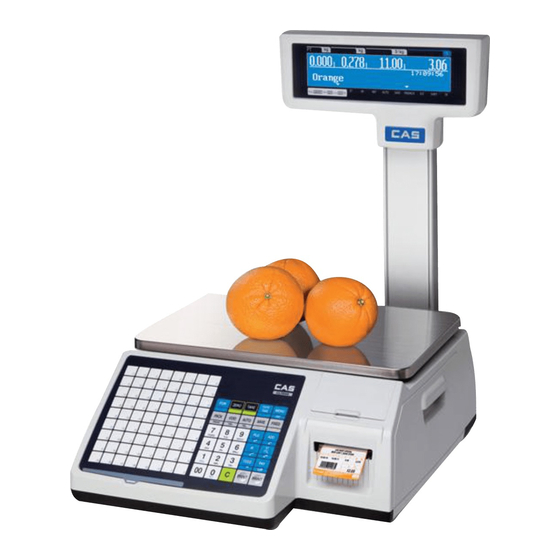
AC source from 100V to 240V at 50/ 60Hz with 5% tolerance. NOTE: Please make sure that the power lines used for the CL3500 series are dedicated lines with No high- noise devices (such as compressors, motors, etc) running on it. - Page 11 CAS ELECTRICS CO.,LTD 2. Classification 2.1 Scale Overview CL3 3 3 3 500 500 has has 2 2 2 2 differrnt type differrnt type Standard Standard Type, Type, Pole Type Pole Type..differrnt type differrnt type Standard...
- Page 12 CAS ELECTRICS CO.,LTD 2.2 Display and Indicators There is LCD(208x48) display on CL3500. LCD display indicates program tare, weight, unit price, total price. Underbar inicates stable, net, zero, auto, save, prepack, D/ C, shift, data transfer. LCD display shows menu massages for program mode.
- Page 13 CAS ELECTRICS CO.,LTD Indicators ■ ■ ■ ■ SYMBOLS DESCRIPTION B, P, R, H - TYPE G - TYPE D - TYPE STABLE Stable weight indicator ▶ ▶ ▶ ◀ Zero weight indicator Net weight indicator AUTO AUTO Print Mode indicator...
- Page 14 CAS ELECTRICS CO.,LTD 2.3 Printer •Cartridge type print mechanism •High quality ROHM printer head (50km/5x10 7 pulses) •Improved a rotating force by using 2 independent motors •Large compartment for 120mm paper roll •High speed at 100 mm/sec. •5 speed ranges for paper roll quality adjustment •Supports Paper...
-
Page 15: C L A S S I F I C A T I O
CAS ELECTRICS CO.,LTD 2.4 Commuication Standard ■ RS232 ① P/S 2 ② Cash Drawer ③ Ethernet ④ USB (Virtual COM) ⑤ Options ■ Wireless Ethernet Module ⑥ Wireless Ethernet Module ④ USB(Virtual COM PS/2 Ethernet RJ45 ③ RS232 ① C ash Drawer... - Page 16 CAS ELECTRICS CO.,LTD 2.5 Key Pad Key pad is like following picture (This may Key pad is like following picture (This may change change depands on contury) depands on contury) Key pad is like following picture (This may Key pad is like following picture (This may...
-
Page 17: G E T T I N G S T A R T E
CAS ELECTRICS CO.,LTD 3. Getting Started 3.1 Sealing Method Method 1 ■ ■ ■ ■ Method 2 ■ ■ ■ ■ Method 3 ■ ■ ■ ■ Method 4 ■ ■ ■ ■... - Page 18 CAS ELECTRICS CO.,LTD 3.2 Installation of the Label Roll Label Specifications ■ ■ ■ ■ Outer diameter of roll : 100mm Inner diameter of roll : 40mm Width of receipt roll : 40, 50, 60mm Width of label roll : 60mm(MAX) Print Area ■...
- Page 19 CAS ELECTRICS CO.,LTD 3) Remove cartridge as fig. 3. 4) Remove Pick- Up Spool assembley and paper guide from the cartridge as fig. 4. 5) Place the label in the scale as fig. 5 6) Press the FEED key. NOTE: For auto label calibration press FEED key two or three times...
- Page 20 CAS ELECTRICS CO.,LTD 3.3 Turning Power On/Off W h e n y o u t u r n o n s c a l e , d i s p l a y w i l l s h o w 9 ~ 0 f o r s e l f t e s t i n g .
- Page 21 CAS ELECTRICS CO.,LTD 3.4 Program Menu and Tree 3.4.1 How to access PROGRAM MODE You can see the Program Menu screen by pressing the MENU key. You can see the Program Menu screen by pressing the MENU key. You can see the Program Menu screen by pressing the MENU key.
- Page 22 CAS ELECTRICS CO.,LTD 3.4.2 Program Menu Tree CODE Menu CODE Sub Menu CODE Sub Menu 1100 1110 Change Price 1120 New/Edit 1120 1130 Discount 1131 New/Edit 1132 List 1133 Delete 1137 Delete by PLU(DC) 1138 Delete by Dept(DC) 1139 Delete All...
- Page 23 CAS ELECTRICS CO.,LTD 1600 Report 1610 X1 Report 1611 Scale 1612 1613 Misc. PLU 1614 Group 1615 Department 1616 Hourly 1617 Clerk 1620 Z1 Report 1630 X2 Report 1631 Scale 1632 1633 Misc. PLU 1634 Group 1635 Department 1636 Hourly...
- Page 24 CAS ELECTRICS CO.,LTD 1900 Communication 1910 Network Setting 1911 Service Type 1912 DHCP 1913 1914 Remote IP 1915 RS232C 1916 WLAN Setting 1917 WLAN Config 1920 Application 1930 Scale Lock/Unlock 1940 Check Scale 1950 Backup to scale 3.4.3 Calibration Menu Tree...
- Page 25 CAS ELECTRICS CO.,LTD 4. Calibration Mode 4.1 Calibration ( C a l i b r a t i o n M E N U - > 1 . C a l i b r a t i o n )
- Page 26 CAS ELECTRICS CO.,LTD F i r s t p a g e o f C a l i b r a t i o n m o d e CALIBRATION MODE (1/2) 1. Calibration 8000 ModE 2. System Options 3. Printer Hardware 4.1.1 Span Calibration (Menu Code 8110)
- Page 27 CAS ELECTRICS CO.,LTD Display shows “Wait4” ~ “Wait0” then following message CALIBRATION (1/3) 1. Span Calibration 8100 ModE 2. Span/Zero Fine Adjust 3. Capacity & Units Error Message * When tray is unstable during calibration process, following message appear. Cal Error – Unstable (0x01)
- Page 28 CAS ELECTRICS CO.,LTD 4.1.2 Span/Zero Fine Adjust (Menu Code 8120) ( C a l i b r a t i o n M E N U - > 1 . C a l i b r a t i o n - > 2 . S p a n / Z e r o F i n e A d j u s t ) This mode is for fine tuning of scale after span Cal.
- Page 29 CAS ELECTRICS CO.,LTD * Insert setting value by number key pad - Set Span value: use curser key to highlight span value. - Type estimate value using number key then press “TEST” key for results # This process may take several times to set 60000.
- Page 30 CAS ELECTRICS CO.,LTD 4.1.3 Capacity & Units (Menu Code 8130) ( C a l i b r a t i o n M E N U - > 1 . C a l i b r a t i o n - > 3 . C a p a c i t y & U n i t s ) Set scale’s Weighing unit, capacity, Interval, Cal Unit.
- Page 31 CAS ELECTRICS CO.,LTD 4.1.4 Gravity Constant (Menu Code 8140) ( C a l i b r a t i o n M E N U - > 1 . C a l i b r a t i o n - > 4 . G r a v i t y C o n s t a n t ) CL-5000 scale enables to calibrate in any country.
- Page 32 CAS ELECTRICS CO.,LTD Guatemala Guatemala 9.7844 Boston 9.8039 Hungary Budapest 9.8069 Chicago 9.8024 Indonesia Djakarta 9.7814 Dallas 9.7949 Iraq Baghdad 9.7964 Detroit 9.8039 Japan Mishima 9.7979 Los Angeles 9.7979 Korea Seoul 9.7994 New York 9.8024 Kuwait Kuwait 9.7919 Philadelphia 9.8024...
- Page 33 CAS ELECTRICS CO.,LTD 4.1.6 Linearity Adjust (Menu Code 8160) ( C a l i b r a t i o n M E N U - > 1 . C a l i b r a t i o n - > 6 . L i n e a r i t y A d j u s t ) You can re-adjust the med-range weight level for precise calibration.
- Page 34 CAS ELECTRICS CO.,LTD 4.1.7 Zero & Tare Setting (Menu Code 8170) ( C a l i b r a t i o n M E N U - > 1 . C a l i b r a t i o n - > 7 . Z e r o & T a r e S e t t i n g ) CAUTION: This Setting is part of (OIML, NTEP, etc) regulation must be setting by the local restriction.
- Page 35 CAS ELECTRICS CO.,LTD Overload Range(d) ④ You can set the maximum overload range. For example, [9] set as 15.045g (5gx[9]=45g). If the weight is over 15.045 overload message will appear. Accumulation(Y/N) ⑤ You can set Tare weights additively. This is useful additional package is used for different goods.
- Page 36 CAS ELECTRICS CO.,LTD 4.2.4 Linearity Fine Adjust (Menu Code 8184) ( C a l i b r a t i o n M E N U - > 1 . C a l i b r a t i o n - > 8 . F a c t o r y S e t t i n g - > 4 . L i n e a r i t y F i n e A d j u s t ) ①...
- Page 37 CAS ELECTRICS CO.,LTD 4.2.5 Hysteresys Calibration (Menu Code 8185) ( C a l i b r a t i o n M E N U - > 1 . C a l i b r a t i o n - > 8 . F a c t o r y S e t t i n g - > 5 . H y s t e r e s y s C a l i b r a t i o n ) S electing “Hysteresys Calibration”...
- Page 38 CAS ELECTRICS CO.,LTD Put on the Weight for Max. Capacities then press “PRINT” ⑦ *Menu 8130 sets the max capacity for calibration. SPAN CALIBRATION (3/4) - Place 6.000 kg on the platter. WAit4 83752 111522 - Press PRINT when ready.
-
Page 39: F L A S H A L L C L E A R ( M E N U C O D
CAS ELECTRICS CO.,LTD 4.3 Memory Clear ( C a l i b r a t i o n M E N U - > 2 . S y s t e m O p t i o n s - > 1 . C l e a r M e m o r y ) You can clear memory depends on options below. -
Page 40: S C A L E T Y P
CAS ELECTRICS CO.,LTD 4.4 Scale Type M e n u C o d e 8 2 2 0 ( C a l i b r a t i o n M E N U - > 2 . S y s t e m O p t i o n s - > 2 . S c a l e T y p e ) Select model: Basic type (CL3500-B), pole type, (CL3500- P) CAUTION: Selecting wrong model code will effect on key function. -
Page 41: P R I N T E R H A R D W A R
CAS ELECTRICS CO.,LTD 4.5 Printer Hardware Sub-menus Description Select label, ticket, continuous label mode. Print Mode Lable mode: “Width(60)”, “Height(40)” and “Gap length(2)” Label / Ticket Ticket mode: “Width(60)”, “Feed(20)” and “End Margin(5)” Size Continous Label: “Width(60)”, “Feed(40)” and “End Margin(2)”... -
Page 42: S E N S O R C A L I B R A T I O N ( M E N U C O D
CAS ELECTRICS CO.,LTD 4.5.3 Sensor Calibration (Menu Code 8330) ( C a l i b r a t i o n M E N U - > 3 . P r i n t e r H a r d w a r e - > 3 . S e n s o r C a l i b r a t i o n ) You can input “Gap,”... -
Page 43: N E T W O R K O P T I O N
CAS ELECTRICS CO.,LTD 4.6 Network Options 5.6.1 Enable Interface (Menu Code 8410) ( C a l i b r a t i o n M E N U - > 4 . N e t w o r k O p t i o n s - > 1 . E n a b l e I n t e r f a c e ) You can set usage of I/O interface.(CL5000) -
Page 44: K E Y B O A R D T E S T ( M E N U C O D
CAS ELECTRICS CO.,LTD 4.7.3 Keyboard Test (Menu Code 8530) ( C a l i b r a t i o n M E N U - > 5 . S e l f T e s t - > 3 . K e y b o a r d T e s t ) You can test keyboard by pressing. -
Page 45: C H E S S P R I N T ( M E N U C O D
1. The rubber roller may be dirty or have something stuck to it. Also, the roller may be perforated. 2. This is a clear indication that the TPH has been damaged or burned out. If you need to replace the TPH, please contact the CAS Service Department. 4.7.5 Printer Sensor Test (Menu Code 8550) ( C a l i b r a t i o n M E N U - >... -
Page 46: M E M O R Y I N F O R M A T I O N ( M E N U C O D
CAS ELECTRICS CO.,LTD Test Items Description Peel-off Cheek Peel-off senor stops label Head-up Cheek TPH head is open or not Cheek label’s gap Peel Peel-off sensor value 4.7.6 Memory Information (Menu Code 8560) ( C a l i b r a t i o n M E N U - > 5 . S e l f T e s t - > 6 . M e m o r y I n f o r m a t i o n ) You can install expansion memory-pack up to 6MB Current memory show as O unused memory as X (each 0 is 1MB). -
Page 47: S E R V I C I N G & P A R T S R E P L A C E M E N
CAS ELECTRICS CO.,LTD 5. Servicing & Parts Replacement CL3500-P ■ ■ ■ ■ CL3500-B ■ ■ ■ ■... -
Page 48: P L A T F O R M S A F E T Y O V E R L O A D A D J U S T M E N
CAS ELECTRICS CO.,LTD 5.1 Platform Safety Overload Adjustment 1) Turn power off and remove power cord 2) Remove tray from scale 3) Remove calibration cealing 4) Remove the upper case 5) Put 150% of max weight on platform rear right. This point Allen- bolt should not be... -
Page 49: R E M O V I N G T H E U P P E R C A S
CAS ELECTRICS CO.,LTD 5.2 Removing the Upper Case 1) Turn power off and remove power cord 2) Remove tray from scale (make sure lift right side first and unlock the left hook) 3) Remove printer cartridge 4) Remove 6 bolt from bottom case(for pole type: remove pole mount bolt first) -
Page 50: M A I N B O A R D R E P L A C E M E N
CAS ELECTRICS CO.,LTD 5.3 Main board Replacement 1) Turn power off and remove power cord 2) Remove following cables SMPS Line Key Board Line Display Board Line Printer Lines A/ D Board Line I/ O Line 3) Remove following bolt to remove main board 1. -
Page 51: P O W E R S U P P L Y R E P L A C E M E N
CAS ELECTRICS CO.,LTD 5.4 Power Supply Replacement 1) Turn power off and remove power cord 2) Remove upper case(following 5.2) 3) Remove power lines (2PIN & 5PIN cables) 4) Remove bottom Power module(SMPS) bolt(4) 5) Full forward power module... -
Page 52: L O A D C E L L & A D C O N V E R T E R R E P L A C E M E N
CAS ELECTRICS CO.,LTD 5.5 Load Cell & AD Converter Replacement 1) Turn power off and remove power cord 2) Remove upper case(5.2) 3) Remove upper frame(Load cell moult) bolt L o d e c e l l s u s p a n s i o n b o l t... -
Page 53: P R I N T A S S E M B L Y R E P L A C E M E N
CAS ELECTRICS CO.,LTD 5.6 Print Assembly Replacement 1) Turn power off and remove power cord 2) Remove printer cartridge 3) Remove upper case(5.2) Remove printer connecting bolt Remove printer module (lift upper right side first) Reference following exploed view... -
Page 54: D I S P L A Y R E P L A C E M E N
CAS ELECTRICS CO.,LTD 5.7 Display Replacement 1) Turn power off and remove power cord 2) Remove upper case (5.2) 3) Remove keyboard and display cable of main board D i s p l a y C a b l e... -
Page 55: K E Y B O A R D R E P L A C E M E N T A , B ( W I T H / W I T H O U T B R E A K I N G S E A L I N
CAS ELECTRICS CO.,LTD 5.8 Keyboard Replacement A,B(with/without breaking sealing) A : A : A : A : w i t h b r e a k s e a l i n g w i t h b r e a k s e a l i n g... -
Page 56: I N S T A L L I N G O P T I O N
CAS ELECTRICS CO.,LTD 6. Installing Options A d d i t i o n a l n e t w o r k c a r d i s a v a i l a b l e f o r u n g r a d e 6.1 Installing Wireless Lan Card... -
Page 57: U P D A T
CAS ELECTRICS CO.,LTD 7. Update 7.1 F/W update (CL3500) NOTE: While you are turning on the scale, you must PUSH CAL botton. If you didn’t follow this procedure, scale will not accept any signal from PC. Step1: Connect RS232C to computer... - Page 58 CAS ELECTRICS CO.,LTD Step6: Turn on the scale while CAL botton is pushed. (at this point display will show “RDY”) NOTE: If CAL botton isn’t pushed, scale will not accept any signal from PC. After few second download process will occure...
- Page 59 CAS ELECTRICS CO.,LTD When download finish scale will reboot NOTE: During this procedure power or communication connector is cut off You must redo from step1...
-
Page 60: S C H E M A T I C & D I A G R A M
8. Schematic & Diagrams 8.1 System Block Diagram... -
Page 61: C O N N E C T I O N D I A G R A
8.2 Connection Diagram... -
Page 62: I / O P I N C O N N E C T I O
8.3 I/O Pin Connection... -
Page 63: E X P L O D E D V I E W
Exploded Views Lower Body A’ssy... -
Page 64: U P P E R B O D Y A S S Y ( B - T Y P
Upper Body A’ssy (B-type) -
Page 65: U P P E R B O D Y A S S Y ( P - T Y P
Upper Body A’ssy (P-type) -
Page 66: P R I N T E R A S S
Printer A’ssy... - Page 67 Poll A’ssy...
-
Page 68: Part L I S
10. Part List 10.1 Electronic Part Image Part Code Parts Name DESCRIPTION Q'ty 6 P 0 1 P C L 4 0 0 1 0 M A I N M O D U L E A S S ’ Y M A I N P C B A S S ' Y 6 P 0 0 P C L 4 0 0 1 0 M A I N B A S E P C B A S S ’... - Page 69 6 4 1 2 T P H 0 0 4 9 0 T P H A S S ' Y H H I K - 9 9 4 9 A - X R 5 6 - 9 9 4 9 J R - 1 0 1 ( P O S C A L E , S W I T C H 7 6 1 2 S 0 0 0 0 0 4 2 A C S O C K E T C O N N E C T O R...
- Page 70 7 8 4 0 W 0 0 1 2 3 1 0 C O N N E C T O R W I R E 1 2 p * 1 2 p * 3 1 5 m m ( C L 3 5 0 0 ) 7 8 4 0 W 0 0 6 2 7 5 0 C O N N E C T O R W I R E 6 p * 6 p * 2 7 5 m m ( C L 3 5 0 0 )
- Page 71 10.2 Mechnical Part 10.2.1 Upper Body Ass’y N o . I M A G E C O D E R E V . P A R T N A M E S P E C M A T E R I A L Q ' T Y 2 0 0 0 - A 0 0 - 0 3 2 6 0 U P P E R C A S E C L 3 0 0 0 4 0 8 * 4 4 1 * 1 3 7...
- Page 72 10.2.2 Lower Body Ass’y N o . I M A G E C O D E R E V . P A R T N A M E S P E C M A T E R I A L Q ' T Y A B S + 2 0 0 0 - A 0 0 - 0 3 2 9 0 L O W E R C A S E...
- Page 73 10.2.3 Poll Ass’y N o . I M A G E C O D E R E V . P A R T N A M E S P E C M A T E R I A L Q ' T Y 2 0 0 0 - A 0 0 - 0 3 3 2 0 P _ B R A C K E T C L 3 0 0 0 1 2 0 .
- Page 74 10.2.4 Printer Mechanism Ass’y N o . I M A G E C O D E R E V . P A R T N A M E S P E C M A T E R I A L Q ' T Y A B S + 2 0 0 0 - A 0 0 - 0 3 3 5 0 M E C H B O D Y...
- Page 75 S I L I C O N S H A F T R O L L E R 1 0 0 0 - A 0 0 - 0 3 3 1 C L 3 0 0 0 4 7 . 8 * 2 2 * 1 . 5 t S U S 3 0 4 G U I D E 2 6 2 0 - A 0 0 - 0 0 3 0...
- Page 76 10.2.5 Cartridge Ass’y N o . I M A G E C O D E R E V . P A R T N A M E S P E C M A T E R I A L Q ' T Y 2 0 0 0 - A 0 0 - 0 3 3 8 0 C A R T R I D G E C L 3 0 0 0 2 4 9 * 1 1 0 .
- Page 77 10.2.6 C/T Box Ass’y N o . I M A G E C O D E R E V . P A R T N A M E S P E C M A T E R I A L Q ' T Y 9 1 0 5 - A 0 0 - 0 0 0 9 0 C / T B O X T O O L - P C L 3 0 0 0 5 4 0 * 4 5 0 * 2 8 5...
- Page 78 11. Revision 2 9 - M a y , 2 0 1 2 C L 3 5 0 0 - B P...
Need help?
Do you have a question about the CL3500 Series and is the answer not in the manual?
Questions and answers