
Related Manuals for Harvia Sentiotec PRO-C3


Summary of Contents for Harvia Sentiotec PRO-C3
- Page 1 Sauna control unit Pro C3 PRO-C3 INSTRUCTIONS FOR INSTALLATION AND USE English Version 04/18 ID no. 1-026-969...
-
Page 2: Table Of Contents
Table of Contents About this instruction manual Important information for your safety 2.1. Intended use 2.2. Safety information for the installer 2.3. Safety information for the user Product description 3.1. Scope of delivery 3.2. Optional accessories 3.3. Product functions 3.4. Sauna operating modes 3.5. - Page 3 5.10. Connecting the safety shut-off 5.11. Remote start 5.12. Status output 5.13. Finishing installation Performing tests Connection diagram Starting up 8.1. Function selection switch settings 8.2. Settings in the technician menu Operating elements 9.1. Description of the operating elements 9.2. The function selector 9.3.
- Page 4 10.13. Cancelling the post-drying programme 10.14. Switching off functions 10.15. Switching off the sauna control unit 11. User program 11.1. Preset user programs 11.2. Accessing user programs 11.3. Creating your own user programs 12. The Eco-function 13. Cleaning and maintenance 13.1.
-
Page 5: About This Instruction Manual
Instructions for installation and use p. 5/54 1. About this instruction manual Read these instructions for installation and use carefully and keep them within reach of the sauna control unit. This ensures that you can refer to information regarding your safety and regarding operation at any time. These installation and operating instructions can also be found in the downloads section of our website: www.sentiotec.com/downloads. -
Page 6: Important Information For Your Safety
Instructions for installation and use p. 6/54 2. Important information for your safety The sauna control unit Pro C3 has been produced in accordance with the applicable safety regulations for technical units. However, hazards may occur during use. Therefore adhere to the following safety information and the specific warning notices in the individual chapters. -
Page 7: Safety Information For The Installer
Instructions for installation and use p. 7/54 2.2. Safety information for the installer ● Installation may only be performed by a qualified electrician or similarly qualified person. ● Work on the sauna control unit may only be performed when the power has been disconnected. -
Page 8: Safety Information For The User
Instructions for installation and use p. 8/54 2.3. Safety information for the user ● The sauna control unit must not be used by children under 8 years old. ● The sauna control unit may only be used by children above 8 years old, by persons with limited psychological, sensory or mental capabilities or by persons with lack of experience/knowledge: –... -
Page 9: Product Description
Instructions for installation and use p. 9/54 3. Product description 3.1. Scope of delivery ● Sauna control unit ● Heater sensor with integrated excess temperature fuse ● Installation material ● Wire jumper for bridging terminals V1 and Wm for combi heaters without low-water shut-off 3.2. - Page 10 Instructions for installation and use p. 10/54 ● Status output ● Preset time function (up to 24 hours) ● Additional output Either for dimming (up to 500 W), switching (up to 3.5 kW) or regulating the sauna room temperature via the additional output. The additional output has no excess temperature fuse.
-
Page 11: Sauna Operating Modes
Instructions for installation and use p. 11/54 ● Excess temperature fuse The excess temperature fuse is installed in the housing for the heater sen- sor. Should the sauna heater continue heating after reaching the preferred temperature due to a defect, the excess temperature fuse switches the sauna heater off at a temperature of approx. - Page 12 Instructions for installation and use p. 12/54 In single-sensor mode, the sauna control unit only displays the set temperature as standard. The actual temperature is not displayed. Should the sauna control unit display the temperature above the heater (F1) as an actual temperature in single-sensor mode, it must be activated when starting up for the first time (see 8.2.
-
Page 13: Installation
Installation instructions, only for experts p. 13/54 4. Installation 4.1. Installing the sauna control unit ATTENTION! Damage to the unit The sauna control unit is protected against jets of water, however direct contact with water could still damage the unit. ●... - Page 14 Installation instructions, only for experts p. 14/54 To install the sauna control unit, perform the following steps: 1. Screw two Phillips-head screws (16 mm) into the wall of the sauna at a height of approx. 1.70 m to a distance of up to 7 mm. The two screws must be placed at a distance of 145 mm from each other (see Fig.
-
Page 15: Installing The Heater Sensor F1 With Excess Temperature Fuse
Installation instructions, only for experts p. 15/54 4.2. Installing the heater sensor F1 with excess temperature fuse Observe the following points when installing the heater sensor: ● The heater sensor must be installed on the rear of the heater, above the mid- dle of the sauna heater. -
Page 16: Installing Bench Sensor F2 (Optional)
Installation instructions, only for experts p. 16/54 4.3. Installing bench sensor F2 (optional) The bench sensor must be installed on the wall of the sauna room, above the rear bench seat. An interval of approx. 15 cm to the roof of the sauna room must be maintained. -
Page 17: Installing The Foil Sensor (Optional)
Installation instructions, only for experts p. 17/54 4.5. Installing the foil sensor (optional) If one of the following infrared heat plates is connected to an additional output, the foil sensor P-ISX-FF must be used: ● IR-WP-100 ● IR-WPHL-100 ● IR-WP-175 ●... -
Page 18: Electrical Connection
Installation instructions, only for experts p. 18/54 5. Electrical connection ATTENTION! Damage to the unit ● The sauna control unit may only be used for operating and controlling 3 heat- ing circuits with a maximum heating capacity of 3.5 kW per heating circuit. The maximum evaporator capacity totals 3.5 kW. -
Page 19: Connecting The Power Supply Cable, Heater And Evaporator
Installation instructions, only for experts p. 19/54 Observe the following points when connecting the power to the sauna control unit: ● Installation may only be performed by a qualified electrician or similarly quali- fied person. Please observe that in the event of a guarantee claim, a copy of the bill from the electrician performing the work must be presented. -
Page 20: Connecting The Fan (Optional)
Installation instructions, only for experts p. 20/54 5.3. Connecting the fan (optional) 1. Guide the light cable through the cable bushing b into the connection area for 230 V/400 V f. 2. Connect the fan cable to the terminal strip d in accordance with the connec- tion diagram. -
Page 21: Connecting Heater Sensor F1
Installation instructions, only for experts p. 21/54 5.6. Connecting heater sensor F1 1. Guide the wires for the heater sensor through the cable bushing 5 into the low-voltage connection area 1. 2. Connect the red wires for the heater sensor to the terminals labelled “STB” in terminal strip 2. -
Page 22: Connecting The Safety Shut-Off
Installation instructions, only for experts p. 22/54 5.10. Connecting the safety shut-off EN 60335-2-53 states that sauna control units with remote control may only be used for operating and regulating a sauna heater which has satisfied the combus- tion test described in paragraph 19.101. Alternatively, a suitable safety shut-off device can be installed in or above the heater. -
Page 23: Status Output
Installation instructions, only for experts p. 23/54 5.12. Status output Any electrical device can be connected to the status output terminal which is suitable for 24 V DC voltage and draws a current no greater than 200 mA. Make sure the polarity is correct when connecting a device. When LEDs are used, a suitable series resistor must be used. -
Page 24: Performing Tests
Installation instructions, only for experts p. 24/54 6. Performing tests WARNING! The following tests must be performed with the power supply switched on. There is a danger of electric shock. ● NEVER touch live parts. The following tests must be performed by a certified electrical fitter. 1. - Page 25 Installation instructions, only for experts p. 25/54 3. Check the phase circuit for sauna mode L1, L2, L3 is connected to U, V, W. 4. Check the phase circuit for evaporator mode L1, L2, L3 is connected to U, V1, W. 5.
-
Page 26: Connection Diagram
Installation instructions, only for experts p. 26/54 7. Connection diagram... -
Page 27: Starting Up
Installation instructions, only for experts p. 27/54 8. Starting up 8.1. Function selection switch settings The function selection switch in the low-voltage connection area allows a variety of product functions to be activated. The figure at the right shows the standard setting for the function selection switch. - Page 28 Installation instructions, only for experts p. 28/54 Activating/deactivating phase alignment Phase alignment is activated or deactivated using the function selection switch 3. ● The function selection switch 3 is set to the ON position as standard. Phase alignment is therefore activated. ●...
-
Page 29: Settings In The Technician Menu
Installation instructions, only for experts p. 29/54 8.2. Settings in the technician menu Opening the technician menu Additional settings can be made in the technician menu. To access the technician menu, perform the following steps: 1. Switch off the sauna control unit. 2. - Page 30 Installation instructions, only for experts p. 30/54 Displaying the heater temperature in single-sensor mode In single-sensor mode, the sauna control unit only displays the set temperature as standard. The actual temperature is not displayed. Should the sauna control unit display the temperature above the heater (F1) as an actual temperature in single-sensor mode, it must be activated in the technician menu.
- Page 31 Installation instructions, only for experts p. 31/54 Activating simultaneous display of the temperature and humidity To activate simultaneous display of the temperature and humidity, carry out the following steps: 1. Open the technician menu (see 29). 2. Turn the top knob to the temperature symbol (position A – see point 9.2 on page 34).
- Page 32 Installation instructions, only for experts p. 32/54 Activating/deactivating the foil sensor If an infrared heat plate is connected to an additional output, the P-ISX-FF foil sen- sor must be used. The foil sensor must be activated. Perform the following steps: 1.
- Page 33 Installation instructions, only for experts p. 33/54 Setting the fan operating mode The fan can either be regulated or switched on and off. The dimmer switch func- tion for the fan is activated as standard. If you wish to deactivate the dimmer switch function for the fan, perform the following steps: 1.
-
Page 34: Operating Elements
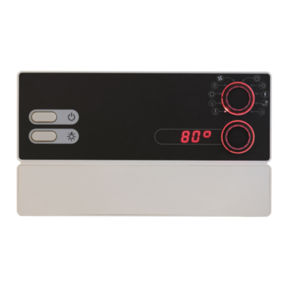
Instructions for use for the user p. 34/54 9. Operating elements 9.1. Description of the operating elements Additional display Intensity display Function selector Light switch Intensity selector ON/OFF switch 9.2. The function selector The function selector 2 allows you to define which function needs to be changed with the intensity selector 3. -
Page 35: The Intensity Selector 35 En
Instructions for use for the user p. 35/54 9.3. The intensity selector The intensity selector 3 allows you to adjust the intensity or output of each function which is selected on the function selector 2. ● Turn the intensity selector 3 to the right to increase the output. ●... -
Page 36: Switching On The Sauna Control Unit
Instructions for use for the user p. 36/54 10.2. Switching on the sauna control unit WARNING! Risk of fire Flammable objects that are placed on the sauna heater could ignite and cause fires. ● NEVER place flammable objects on the sauna heater. ●... -
Page 37: Starting Combi Mode
Instructions for use for the user p. 37/54 10.4. Starting combi mode 1. Turn the function selector 2 to position A (temperature). ► The temperature symbol lights up. 2. Use the intensity selector 3 to set the preferred temperature. 3. Press the intensity selector 3. ►... -
Page 38: Starting Additional Output
Instructions for use for the user p. 38/54 The evaporator (humidity function B) can only be started when the sauna heater (temperature function A) is switched on. The maximum humidity level which can be set depends on the temperature of the sauna. The higher the sauna temperature, the lower the maximum humidity level which can be set. - Page 39 Instructions for use for the user p. 39/54 2. Press the bottom knob for one second. ► The mode you just selected is shown in the top display: ● Display: “StEP” – the additional output is in intensity regulation mode. ●...
-
Page 40: Switching On The Light
Instructions for use for the user p. 40/54 Room temperature control with the additional output If the mode of the additional output is set to room temperature regulation, a sauna room temperature can be set, which is regulated using the additional output. This can be used to regulate the sauna room temperature using only infrared lamps or infrared heat plates. -
Page 41: Starting The Fan
Instructions for use for the user p. 41/54 When the dimmer switch function is deactivated When the dimmer function for the light has been deactivated, you can only switch the light on and off. The light will always operate at full power. 1. -
Page 42: Setting The Preset Time
Instructions for use for the user p. 42/54 When the dimmer switch function is deactivated When the dimmer switch function for the fan has been deactivated, you can only switch the fan on and off. The device will always operate at full power. 1. -
Page 43: Cancelling The Preset Time Function
Instructions for use for the user p. 43/54 2. Turn the function selector 2 to position F (preset time). ► The most recently set preset time is shown in the intensity display 4. 3. Use the intensity selector 3 to set the preferred preset time. 4. -
Page 44: Activating Standby For Remote Operation
Instructions for use for the user p. 44/54 3. To save the operating time permanently, press the bottom knob for one second. ► The bottom knob lights up 4 times – the setting is saved. If you want to set long durations, use the quick preset function: ●... -
Page 45: Cancelling The Post-Drying Programme
Instructions for use for the user p. 45/54 10.13. Cancelling the post-drying programme after the combi-mode, the post-drying programme is started automatically. This involves heating the sauna room to 80 °C with the fan running for 30 min- utes. In the intensity display 4, the text “dry” is displayed and the temperature symbol flashes. -
Page 46: User Program
Instructions for use for the user p. 46/54 11. User program The user program enables favourite sauna settings to be saved and accessed again. There are 5 preset user programs available which can be modified ac- cording to user requirements. The settings of the following functions are stored in the user programs: ●... -
Page 47: Accessing User Programs
Instructions for use for the user p. 47/54 11.2. Accessing user programs 1. Turn the function selector 2 to position H (user programs). ► The user symbol lights up. 2. Use the intensity selector 3 to select a user program (1–5). 3. - Page 48 Instructions for use for the user p. 48/54 Perform the following steps to save the settings in the table above in user program 2: 1. Turn the function selector 2 to position A (temperature). ► The temperature symbol lights up. 2.
-
Page 49: The Eco-Function
Instructions for use for the user p. 49/54 12. The Eco-function The Eco-function allows you to save energy in breaks between sauna sessions. When the Eco-function is activated, the connected devices run with reduced power. You can choose between a 20-, 40- or 60-minute sauna break. The sauna heater and the evaporator are switched on again before the end of the break. -
Page 50: Cleaning And Maintenance
Instructions for use for the user p. 50/54 13. Cleaning and maintenance 13.1. Cleaning ATTENTION! Damage to the unit The sauna control unit is protected against jets of water, however direct contact with water could still damage the unit. ● Never immerse the device in water. ●... -
Page 51: Troubleshooting
Installation instructions, only for experts p. 51/54 15. Troubleshooting 15.1. Error messages The sauna control unit is equipped with diagnostic software which monitors system statuses when it switches on and during operation. As soon as the diagnostic software identifies an error, the sauna control unit switches the sauna heater off. Errors are indicated by a recurring warning tone and by flashing on the function selector 2 and the intensity selector 3. -
Page 52: Low-Water Display
Instructions for use for the user p. 52/54 15.2. Low-water display The sauna control unit features an automatic low-water shut-off feature which is active in combi mode, as long as your combi heater supports it. If the water tank in the evaporator is empty, this is indicated by a recurring warn- ing tone and the text “FILL”... -
Page 53: Technical Data
Instructions for installation and use p. 53/54 16. Technical data Ambient conditions Storage temperature: -25 °C to +70 °C Ambient temperature: -10 °C to +40 °C Relative humidity: max. 95 % Sauna control unit Dimensions: 307 x 175 x 57 mm Switched voltage / three-phase 3N: 400 V AC Frequency:... - Page 54 Instructions for installation and use p. 54/54 Setting ranges Temperature: 30 °C to 110 °C Humidity: 0 % to 100 % The maximum humidity level which can be set depends on the temperature of the sauna. The higher the sauna temperature, the lower the maximum humidity level which can be set.
- Page 55 NOTIZEN / APPUNTI / NOTES / NOTE / NOTITIES ………………………………………………….....………………………………………………………………... ……………………………………………………………..……………………………………………………………... …………………………………………………………….....………………………………………………………... …………………………………………………….....………………………………………………………………... ……………………………………………………………..……………………………………………………………... ……………………………………………………………..……………………………………………………………... ……………………………………………………………..…………………………………………………………... …………………………………………………………….....………………………………………………………... …………………………………………………………….....………………………………………………………... …………………………………………………………….....………………………………………………………... …………………………………………………………….....………………………………………………………... …………………………………………………………….....………………………………………………………..…………………………………………………………….....………………………………………………………... …………………………………………………………….....………………………………………………………... …………………………………………………………….....………………………………………………………... …………………………………………………………….....………………………………………………………... …………………………………………………………….....………………………………………………………... …………………………………………………………….....………………………………………………………... …………………………………………………………….....………………………………………………………...
- Page 56 GmbH | Division of Harvia Group | Oberregauer Straße 48, A-4844 Regau T +43 (0) 7672/277 20-567 | F -801 | info@sentiotec.com | www.sentiotec.com...
Need help?
Do you have a question about the Sentiotec PRO-C3 and is the answer not in the manual?
Questions and answers