Table of Contents
Advertisement
Quick Links
Firmware: v.1.0 or higher
•
Input type: pulse
•
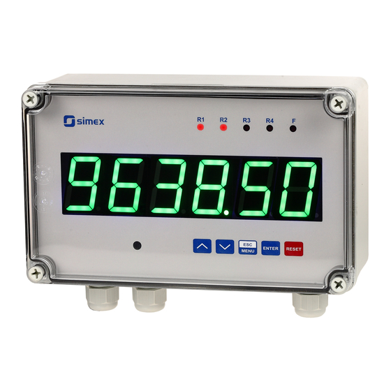
Rotational / linear speed control, Wall-mounted case IP 67
•
Read the user's manual carefully before starting to use the unit or software.
Producer reserves the right to implement changes without prior notice.
2018.12.18
User manual
RATEMETER
STI-638
Assisting the automation
industry since 1986
STI-638_INSSXEN_v.1.04.001
Advertisement
Table of Contents

Related Manuals for Simex STI-638


Summary of Contents for Simex STI-638
- Page 1 Assisting the automation industry since 1986 User manual RATEMETER STI-638 Firmware: v.1.0 or higher • Input type: pulse • Rotational / linear speed control, Wall-mounted case IP 67 • Read the user's manual carefully before starting to use the unit or software.
-
Page 2: Table Of Contents
User manual - RATEMETER STI-638 CONTENTS 1. BASIC REQUIREMENTS AND USER SAFETY..................3 2. GENERAL CHARACTERISTICS........................4 3. TECHNICAL DATA............................5 4. DEVICE INSTALLATION..........................7 4.1. UNPACKING............................7 4.2. ASSEMBLY............................7 4.3. CONNECTION METHOD........................8 4.4. MAINTENANCE..........................16 5. FRONT PANEL DESCRIPTION........................17 6. PRINCIPLE OF OPERATION........................18 6.1. MEASUREMENT MODE........................18... -
Page 3: Basic Requirements And User Safety
User manual - RATEMETER STI-638 Explanation of symbols used in the manual: - This symbol denotes especially important guidelines concerning the installation and operation of the device. Not complying with the guidelines denoted by this symbol may cause an accident, damage or equipment destruction. -
Page 4: General Characteristics
The device can be equipped with two or four relay (or OC type) outputs. These outputs can be controlled depend on momentary value of rotational speed. Optionally STI-638 with two relays (or OC type) outputs can be equipped with active current output, passive isolated current output or active voltage output. -
Page 5: Technical Data
User manual - RATEMETER STI-638 3. TECHNICAL DATA Power supply voltage 85... 230 ...260V AC/DC; 50 ÷ 60 Hz (separated) (depending on version) or 19...24...50V DC and 16...24...35V AC (separated) External fuse (required) T - type, max. 2 A Power consumption max. - Page 6 User manual - RATEMETER STI-638 Display range 0.00000 ÷ 999999 Frequency measurement accuracy ± 0.02% (full temperature range) Indication precision Selected from range: 0 ÷ 0.00000 Speed unit 1/s, 1/min, 1/h Time between following pulses settable from 0.1 to 39.9 sec.
-
Page 7: Device Installation
User manual - RATEMETER STI-638 4. DEVICE INSTALLATION The unit has been designed and manufactured in a way assuring a high level of user safety and resistance to interference occurring in a typical industrial environment. In order to take full advantage of these characteristics installation of the unit must be conducted correctly and according to the local regulations. -
Page 8: Connection Method
User manual - RATEMETER STI-638 230 mm 96.5 mm 212 mm Figure 4.1. Device and assembly dimensions of the case 4.3. CONNECTION METHOD Caution - Installation should be conducted by qualified personnel . During installation all available safety requirements should be considered. The fitter is responsible for executing the installation according to this manual, local safety and EMC regulations. - Page 9 User manual - RATEMETER STI-638 - Unused clamps (marked as n.c.) must not be used for connecting any connecting cables (e.g. as bridges), because this can cause damage to the equipment or electric shock. - If the unit is equipped with housing, covers and sealing packing, protecting against water intrusion, pay special attention to their correct tightening or clamping.
- Page 10 User manual - RATEMETER STI-638 Connections of power supply voltage and measurement signals are executed using the screw connections on the back of the unit’s housing. 6-7 mm Figure 4.2. Method of cable insulation replacing and cable terminals All connections must be made while power supply is disconnected !
- Page 11 User manual - RATEMETER STI-638 +24V +5%, -10% Power Imax = 100mA (optional) supply DATA+ - Uo + (optional) DATA- (depending on version) 7 8 9 10 11 12 13 14 15 16 17 18 19 20 n.c. n.c. n.c.
- Page 12 User manual - RATEMETER STI-638 +24V +5%, -10% Power Imax = 100mA (optional) (optional) (optional) (optional) supply DATA+ - Uo + DATA- (depending on version) 13 14 15 16 17 18 19 20 9 10 11 12 n.c. n.c. n.c.
- Page 13 User manual - RATEMETER STI-638 Contacts of relay outputs are not equipped with spark suppressors. While use the relay outputs for switching of inductive loads (coils, contactors, power relays, electromagnets, motors etc.) it is required to use additional suppression circuit (typically capacitor 47nF/ min. 250VAC in series with 100R/5W resistor), connected in parallel to relay terminals or (better) directly on the load.
- Page 14 User manual - RATEMETER STI-638 - Uo + 16 17 18 19 20 n.c. n.c. n.c. pulse input NPN type sensor Figure 4.14. An example of sensor connection with common plus 9 10 16 17 Logic controller Voltage input 24 V...
- Page 15 User manual - RATEMETER STI-638 ACTIVE current output (optional) 11 12 Logic controller current input 0-20 mA Figure 4.16. Example of active current outputs connection (for device with active current output only) Passive, isolated Current output 4÷20mA (optional) 11 12...
-
Page 16: Maintenance
User manual - RATEMETER STI-638 4.4. MAINTENANCE The unit does not have any internal replaceable or adjustable components available to the user. Pay attention to the ambient temperature in the room where the unit is operating. Excessively high temperatures cause faster ageing of the internal components and shorten the fault-free time of unit operation. -
Page 17: Front Panel Description
User manual - RATEMETER STI-638 5. FRONT PANEL DESCRIPTION Thresholds exceeding LED alarm LED indicator (F) indicators (R) display infrared receiver programming ENTER RESET pushbuttons MENU Symbols and functions of push-buttons: Symbol used in the manual: [ESC/MENU] Functions: MENU •... -
Page 18: Principle Of Operation
User manual - RATEMETER STI-638 6. PRINCIPLE OF OPERATION After turning the power supply on, device ID and software version are showed on the display, next the controller goes to the measurement mode. 6.1. MEASUREMENT MODE In the measurement mode the device shows current measurement value (rotational revolution, it depends on “F or P”... -
Page 19: Detection Of The Peak Values
. 6.2. DETECTION OF THE PEAK VALUES The STI-638 controller is equipped with peaks detection function. It can detect a peaks of the input signal and display their values. Presets connected with this function are placed in “HOLd” menu (see description of “HOLd” menu). The detection of the peak can be done if the measured signal raises and drops of value at least equal to parameter “PEA”... -
Page 20: Control Of The Relay Outputs
User manual - RATEMETER STI-638 6.3. CONTROL OF THE RELAY OUTPUTS The control of the object (measured signal) is realized via relay outputs. Front panel LEDs named „ R ” indicates the state of particular relay output. If device is not equipped with one or more relay outputs, menus refer to this relays are available, but apply to LED indicators only. -
Page 21: One Threshold Mode
User manual - RATEMETER STI-638 6.3.1. One threshold mode Figure 6.4 presents the principle of relay outputs operation for one threshold mode, and an example values of other parameters. measured “SEt P” parameter displayed value signal (expected signal value) zone A “HYSt”... -
Page 22: Two Thresholds Mode
User manual - RATEMETER STI-638 (when input signal stay in zone A or zone B) are lower than parameters “t on” If t or t or “t oFF”, the relay will not change his state (see points A and C, Figure 6.4 a, d, e). -
Page 23: Device Programming
User manual - RATEMETER STI-638 Figure 6.5 presents the principle of relay outputs operation for two thresholds mode, and an example values of other parameters. In this mode parameter “SEt P2” is accessible in common with “SEt P2” , this parameter describes a second threshold of the relay output. The parameters “HYSt”, “modE”, “t on”, “t oFF”, “unit”... -
Page 24: Parameters Edition
User manual - RATEMETER STI-638 Functions of the buttons while sub-menu and parameters choice: Selection of sub-menu or parameter for editing. Name of selected item (sub- menu or parameter) is displayed. Operation of [ENTER] button depend on present menu position: ENTER •... -
Page 25: Switch Parameters ("List" Type)
User manual - RATEMETER STI-638 7.2.3. Switch parameters (“LIST” type) Switch parameters can be described as a sets of values (a lists) out of which only one of the options available on the list can be selected for the given parameter. Options of switching parameter are selected using keys. - Page 26 User manual - RATEMETER STI-638 • The relay outputs and LEDs (named “R“) can be controlled depend on both - the current value and the peak value (when peak detection is active) of the input signal. • If device is not equipped with one or more relay outputs, menus refer to this relays are available, but apply to LED indicators only.
-
Page 27: Beep" Menu
User manual - RATEMETER STI-638 LEDs light when relays are closed, independently of relays' mode. • • When power supply fail, unit do not store relays state selected by RS-485 interface. “t on” - turn on delay time, the relay is turned on with delay equal “t on” if the input value exceeds appropriate border value (defined with threshold and hysteresis), at least “t on”... -
Page 28: Input" Menu
User manual - RATEMETER STI-638 7.3.3. “ inPUt ” menu This menu contains options of pulse input configuration: “FrEq” - maximum permitted frequency of pulses delivered to the input. This parameter is expressed in Hz. And can be set to one of all values showed in Tab.7.1. -
Page 29: Filter" Menu
User manual - RATEMETER STI-638 “unit” - The unit of rotational speed used for recalculation of current measurement can be set to: “SEC” - result expressed in revolutions / second “min” - result expressed in revolutions / minute “hour” - result expressed in revolutions / hour “F or P”... -
Page 30: Output" Menu
User manual - RATEMETER STI-638 “droP” - this parameter defines minimum percentage change of measured value which turns off (temporally) data filtration. Value of this parameter can be changed in range: 0 ÷ 199,9%. Main purpose of this parameter is acceleration of displaying data changes, when sudden changes of instantaneous measurements value occur (while parameter “vALUE”... - Page 31 User manual - RATEMETER STI-638 “ OutL ” parameter can be greater than “ OutH ”. In this case the conversion characteristic is reversed, it means that if input value raises the output value falls. ”Lo r”, ”Hi r” - this parameters define the output value range. If calculated output value Out exceeds defined range then analogue output generates signal equal to upper or lower border of the defined range.
-
Page 32: Bright" Parameter
User manual - RATEMETER STI-638 If parameter “OUtmod” is set to “oFF” , “4-20” , “0-20” , “0-5” , “1-5” , “0-10” or “2-10” the “critical situation” means that permissible measurement range is exceeded. If parameter “OUtmod” is set to “modbuS”, the “critical situation” means communication delay (when no data is received) longer than “mbtimE”... -
Page 33: Secu" Menu
User manual - RATEMETER STI-638 7.3.8. ”SECU” menu This menu contains presets connected with availability of other parameters: “SEtcod” - user password (4-digits number). If this parameter is set at value “0000” , user password is turned off. If the user do not remember his password, the access to the menu is possible by the “one-use password”. -
Page 34: Edit T" Parameter
User manual - RATEMETER STI-638 “Std” - answer as quick as possible, no additional delay “ 10c” “ 20c” - answer delayed of 10, 20, 50, 100 of 200 chars respectively, where “ 50c” one character time depends on selected baud rate “100c”... -
Page 35: Menu Structure
User manual - RATEMETER STI-638 7.4. MENU STRUCTURE Measurement mode Press and hold at least 2 seconds MENU MENU 4-digit user password entering (if it is different from „0000”) 0 _ _ _ ENTER ENTER ENTER Parameter MENU rELAy1 SEt P... - Page 36 User manual - RATEMETER STI-638 See previous page ENTER ENTER Parameter MENU HOLd modE edition ENTER MENU timE H dis MENU H r1 H r2 H r3 H r4 HOUt ENTER ENTER Parameter MENU SECU SEtcod edition ENTER MENU Acc r1...
-
Page 37: Examples Of "Mul" And "Div" Parameters Calculation
User manual - RATEMETER STI-638 8. EXAMPLES OF “MUL” AND “DIV ” PARAMETERS CALCULATION 1. Let's assume that user wants to multiply rotational speed by 12.34. Then parameters “mUL” “div” should be set : “mUL” “div” = 1234, = 100 2. -
Page 38: Output Value Calculation
User manual - RATEMETER STI-638 9. OUTPUT VALUE CALCULATION Lets assume that we have active current output and its parameters are: “OUtmod” = “4-20” , “OUt LO” = 100, “OUt HI” = 200, “Lo r” = 5.0, “Hi r” = 5.0 Parameters “Lo r”... - Page 39 User manual - RATEMETER STI-638 Register Write Range Register description 0 ÷ 999999 Measurement value (no decimal point) The status of the current measurement. 0 – data valid; 0-FFh 20h – device waits for first pulse; A0h – alarm state, allowable frequency range is exceeded 0 ÷...
- Page 40 User manual - RATEMETER STI-638 Register Write Range Register description “bAud” parameter in “rS-485” menu (baud rate); 0 ÷ 7 0 - 1200 baud; 1 - 2400 baud; 2 - 4800 baud; 3 - 9600 baud; 4 - 19200 baud; 5 - 38400 baud; 6 - 57600 baud; 7 - 115200 baud “mbAccE”...
- Page 41 User manual - RATEMETER STI-638 Register Write Range Register description Parameters or relay R2 operation 0 ÷ 999999 “SEt P” parameter in “rELAy2” menu, no decimal point included 0 ÷ 99999 “HySt” parameter in “rELAy2” menu, no decimal point included “modE”...
- Page 42 User manual - RATEMETER STI-638 Register Write Range Register description “modE” parameter in “rELAy4” menu: 0 ÷ 5 0 - “noACt” mode; 1 - “on” mode; 2 - “oFF” mode; 3 - “in” mode; 4 - “out” mode; 5 - “modbuS” mode “t on”...
- Page 43 User manual - RATEMETER STI-638 Register Write Range Register description “OUtmod” parameter in “OUtPUt” menu (active current output mode) current output disabled; 1 - current output enabled with 4÷20mA 0 ÷ 3 mode; 2 - current output enabled with 0÷20mA mode;...
-
Page 44: Transmission Errors Description
User manual - RATEMETER STI-638 10.2. TRANSMISSION ERRORS DESCRIPTION If an error occurs while write or read of single register, then the device sends an error code according to Modbus RTU specifications (example message no 5). Error codes: 01h - illegal function (only functions 03h, 06h and 10h are available),... - Page 45 User manual - RATEMETER STI-638 2. Read of device ID code ADDR FUNC REG H,L COUNT H,L CRC L,H The answer: ADDR FUNC BYTE C DATA H,L CRC L,H DATA - identification code (2056h) 3. Change of the device address from 1 to 2 (write to reg. 20h)
- Page 46 User manual - RATEMETER STI-638 Device response ( with exception code 03h): ADDR FUNC CRC L,H There is no full implementation of the Modbus Protocol in the device. The functions presented above are available only.
-
Page 47: Default And User's Settings List
User manual - RATEMETER STI-638 11. DEFAULT AND USER'S SETTINGS LIST Desc. Parameter Description Default value User's value page Parameters of relay R1 operation (“rELAy1” menu) SEt P Relay first threshold 20.0 SEt P2 Relay second threshold 30.0 HYSt Hysteresis of relay... - Page 48 User manual - RATEMETER STI-638 Desc. Parameter Description Default value User's value page t on Turn on delay of relay 0.0 (sec.) t oFF Turn off delay of relay 0.0 (sec.) unit Unit of “t on”, “toFF” parameters of relay „SEC”...
- Page 49 User manual - RATEMETER STI-638 Desc. Parameter Description Default value User's value page OUt HI Display value for 20 mA current output 100.0 Extension of the bottom of the nominal output Lo r 5.0 (%) range Hi r Extension of the top of the nominal output range 5.0 (%)
- Page 50 User manual - RATEMETER STI-638 Desc. Parameter Description Default value User's value page bAud Baud rate 9600 (b./sec.) mbAccE Permission to changes of configuration registers „on” mbtimE Maximum delay between received messages rESP Additional delay of answer transmission „Std” Configuration of numerical parameters edition...
- Page 51 User manual - RATEMETER STI-638...
- Page 52 SIMEX Sp. z o.o. ul. Wielopole 11 80-556 Gdańsk Poland tel.: (+48 58) 762-07-77 fax: (+48 58) 762-07-70 http://www.simex.pl e-mail: info@simex.pl...
Need help?
Do you have a question about the STI-638 and is the answer not in the manual?
Questions and answers