Table of Contents
Advertisement
Quick Links
Firmware: up to v. 5.
•
Input type: pulse
•
Batching and totalizer function
•
Read the user's manual carefully before starting to use the unit or software.
Producer reserves the right to implement changes without prior notice.
2013.08.14
User manual
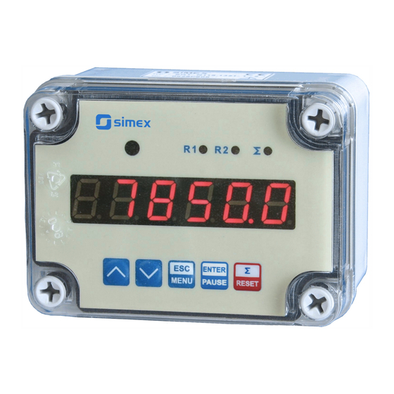
FLOW METER
SPI-N118
11
Assisting the automation
industry since 1986
SPI-N118_INSSXEN_v.2.04.001
Advertisement
Table of Contents

Related Manuals for Simex SPI-N118


Summary of Contents for Simex SPI-N118
- Page 1 Assisting the automation industry since 1986 User manual FLOW METER SPI-N118 Firmware: up to v. 5. • Input type: pulse • Batching and totalizer function • Read the user's manual carefully before starting to use the unit or software. Producer reserves the right to implement changes without prior notice.
-
Page 2: Table Of Contents
User manual for - FLOW METER SPI-N118 CONTENTS 1. BASIC REQUIREMENTS AND USER SAFETY..................3 2. GENERAL CHARACTERISTICS........................4 3. TECHNICAL DATA............................5 4. DEVICE INSTALLATION..........................6 4.1. UNPACKING............................7 4.2. ASSEMBLY............................7 4.3. CONNECTION METHOD........................8 4.4. MAINTENANCE..........................12 5. FRONT PANEL DESCRIPTION........................12 6. PRINCIPLE OF OPERATION........................13 6.1. -
Page 3: Basic Requirements And User Safety
User manual for - FLOW METER SPI-N118 Explanation of symbols used in the manual: - This symbol denotes especially important guidelines concerning the installation and operation of the device. Not complying with the guidelines denoted by this symbol may cause an accident, damage or equipment destruction. -
Page 4: General Characteristics
To allow user to change presets without opening the cover, an IR sensor is mounted. Remote controller keyboard is equivalent to the device keyboard (Note, that remote controller is not a part of the SPI-N118 set – it is an additional equipment). -
Page 5: Technical Data
User manual for - FLOW METER SPI-N118 3. TECHNICAL DATA Power supply voltage 230V AC ± 10%, 50 ÷ 60 Hz (separated) (depending on version) or 110V AC ± 5%, 50 ÷ 60 Hz (separated) or 24V AC ± 5%, 50 ÷ 60 Hz (separated) or 24V DC ±... -
Page 6: Device Installation
User manual for - FLOW METER SPI-N118 Communication interface RS 485, 8N1 and 8N2, Modbus RTU, not separated Baud rate 1200 bit/s ÷ 115200 bit/s Display LED, 6 digit, 13mm height, red Data memory non-volatile memory, EEPROM type Protection level... -
Page 7: Unpacking
User manual for - FLOW METER SPI-N118 - The load must correspond to the requirements listed in the technical data. - All installation works must be conducted with a disconnected power supply. - Protecting the power supply clamps against unauthorized persons must be taken into consideration. -
Page 8: Connection Method
User manual for - FLOW METER SPI-N118 4.3. CONNECTION METHOD Caution - Installation should be conducted by qualified personnel . During installation all available safety requirements should be considered. The fitter is responsible for executing the installation according to this manual, local safety and EMC regulations. - Page 9 User manual for - FLOW METER SPI-N118 Use of screened signal cables is recommended. Signal cable screens should be – connected to the earthing only at one of the ends of the screened cable. In the case of magnetically induced interference the use of twisted couples of signal –...
- Page 10 User manual for - FLOW METER SPI-N118 OC1, OC2: U max = 30V DC, max = 30mA, max = 100mW batching counter clearing balance counter clearing pulse input counting inhibition 12 11 10 9 8 7 6 5 4 3 COM –...
- Page 11 User manual for - FLOW METER SPI-N118 Figure 4.6. Examples of suppression circuit connection: a) to relay terminals; b) to the inductive load counting inhibition balance counter clearing batching counter clearing Figure 4.7. Example of connection between flow counter and flow sensor with contactron output...
-
Page 12: Maintenance
User manual for - FLOW METER SPI-N118 Logic controller LED 10 mA voltage input 24 V Figure 4.8. Example of OC-type outputs connection 4.4. MAINTENANCE The unit does not have any internal replaceable or adjustable components available to the user. Pay attention to the ambient temperature in the room where the unit is operating. -
Page 13: Principle Of Operation
User manual for - FLOW METER SPI-N118 Symbols and functions of push-buttons: Symbol used in the manual: [ESC/MENU] Functions: MENU • Enter to main menu ( press and hold by at least 2 sec.) • Exit the current level and Enter to previous menu (or measure mode) •... - Page 14 User manual for - FLOW METER SPI-N118 alarm state flow counter displays ”-Hi-” message, in place of flow result. • In all other cases (while frequency and pulses duty cycle gets acceptable values) input pulses are delivered to internal prescaler. The prescaler (see description of parameter “PULSEL”) should be set to value equal to the quantity of pulses per one litre.
- Page 15 User manual for - FLOW METER SPI-N118 If instantaneous flow (flow rate) is displayed (LED marked “Σ” is off) or batcher counter • value ( “ Σ ” LED is pulsing), user can check main threshold values and number of batches counter (which indicates how many times batcher was started).
-
Page 16: Detection Of The Peak Values
(after entering to menu mode counting and controlling is continued in “background”. 6.2. DETECTION OF THE PEAK VALUES The SPI-N118 flow meter is equipped with peaks detection function. It can detect a peaks of the input signal and display their values. Presets connected with this function are placed in ”HOLd”... -
Page 17: Control Of The Relay Outputs
User manual for - FLOW METER SPI-N118 6.3. CONTROL OF THE RELAY OUTPUTS The control of the object (measured signal) is done due to instantaneous flow value (current flow rate), total flow counter value or batcher counter value, and is realized via relay outputs. -
Page 18: One Threshold Mode
User manual for - FLOW METER SPI-N118 The relay outputs and LEDs (named R ) can be controlled depend on both - the current value and the peak value (when peak detection is active, for flow rate only) of the input signal. -
Page 19: Two Thresholds Mode
User manual for - FLOW METER SPI-N118 “t on” (see points B , Figure 6.5 a, d, e). Similarly, the relay will be turned off if time “t oFF” elapse since the input signal value exceeds any of the border values (see points , Figure 6.5 a, d, e). -
Page 20: Batcher Mode And „Pre R1" Mode
User manual for - FLOW METER SPI-N118 Figure 6.6 presents the principle of relay outputs operation for two thresholds mode, and an example values of other parameters. In this mode parameter “SEt P2” is accessible in common with “SEt P2” , this parameter describes a second threshold of the relay output. The parameters “HYSt”, “modE”, “t on”, “t oFF”, “unit”... -
Page 21: Use Of The Batcher Counter As A Marker
User manual for - FLOW METER SPI-N118 flows through valve during closing. Number of batches is counted by another counter (number of batches counter) and stored into the non-volatile memory. To display the value of this counter use [^] or [v] button. After that message ”bAtCnt”... -
Page 22: Device Programming
User manual for - FLOW METER SPI-N118 7. DEVICE PROGRAMMING The device menu allow user to set all parameters connected to operation of measurement input, control modes, critical situations behaviour, communication via RS-485 and access settings. The meaning of the particular parameters is described in paragraph MENU DESCRIPTION. -
Page 23: Parameters Edition
User manual for - FLOW METER SPI-N118 After about 1 min. since last use of the buttons, device exits the menu mode and returns to the measurement mode (only if no parameters are in editing mode). 7.2. PARAMETERS EDITION To start edition of any parameter user should select name of desired one using [^] [v] buttons and then press [ENTER] . -
Page 24: Menu Description
User manual for - FLOW METER SPI-N118 Functions of buttons when editing numeric and switching parameters: While editing numeric parameter: • change of current (flashing) digit • slide change of value (acceleration, deceleration, direction change) While editing switch parameter - selection of switch parameter. - Page 25 User manual for - FLOW METER SPI-N118 “bAt” option is available for relay R1 only. For the rest of relays „ PrE r1 ” option is available. „PrE r1” option means controlling in relation to „SEt P” of relay R1 (see CONTROL OF THE RELAY OUTPUTS).
- Page 26 User manual for - FLOW METER SPI-N118 “0.000“ Decimal point position is changed by [^] , [v] buttons. “t unit” - the unit of relay thresholds and hysteresis when relay is controlled due to total flow counter result. It can be set to: “lit.”...
-
Page 27: Input" Menu
User manual for - FLOW METER SPI-N118 “t on” - turn on delay time, the relay is turned on with delay equal “t on” if the input value exceeds appropriate border value (defined with threshold and hysteresis), at least “t on” time. “t on” range 0 ÷ 99.9, defined with 0.1 sec. resolution. Unit of this parameter is set by “unit”... -
Page 28: Flouu" Menu
User manual for - FLOW METER SPI-N118 “FrEq” parameter. If particular state is shorter than showed in Tab.7.1, value of it is interpreted as disturbance and ignored. Parameter Minimum duration Permitted duty cycle ”FrEq” (Hz) of low and high states for max. -
Page 29: Batch" Menu
User manual for - FLOW METER SPI-N118 “F PrEc” - decimal point position (precision of flow rate displaying). It can be set to: “ 0” “ 0.0” “ 0.00” “ 0.000” “ 0.0000” “0.00000” Decimal point position is changed by [^] , [v] buttons. -
Page 30: Total" Menu
User manual for - FLOW METER SPI-N118 Zeroing of batcher counter is possible via RS-485 interface too. It can be done as write of 0000h to any one of registers referred to batcher counter (0Dh ÷ 0Fh) using RS 485 interface. -
Page 31: Bl Inp" Parameter
User manual for - FLOW METER SPI-N118 “ 0“ “ 0.0“ “ 0.00“ “0.000“ Decimal point position is changed by [^] , [v] buttons. “t unit” - the unit of volume (cubic measure) used for total flow counter displaying . It can be set to: (”lit.“... -
Page 32: Init D" Parameter
User manual for - FLOW METER SPI-N118 For settings “stop counting while high/low level” the selected level must be longer than 5ms. 7.3.7. “ Init d ” parameter This parameter defines type of the value displayed after power on the meter. It is possible to set it to: “Flo”... -
Page 33: Secu" Menu
User manual for - FLOW METER SPI-N118 “timE” - maximum time of displaying of the peak (drop) value, can be set from 0.0 to 19.9 sec, with 0.1 sec. resolution. If „HdiS”=”HOLD” then setting parameter "timE"=0.0 causes holding peak value until [ESC] button is pressed. If „ HdiS ”=” rEAL ” then value "timE"=0.0 means no holding. -
Page 34: Edit T" Parameter
User manual for - FLOW METER SPI-N118 The access to registers no 04h i 05h cant be denied by ”mbAccE” parameter (see: LIST OF REGISTERS). ”mbtimE” - this parameter defines maximal time (sec) between following frames received by the device. If the delay will be greater than the value of ”mbtimE” parameter, the relays which are controlled via RS-485 interface, will set to alert state (see “rELAy1”... -
Page 35: Menu Structure
User manual for - FLOW METER SPI-N118 7.4. MENU STRUCTURE Measurement mode Press and hold at least 2 seconds MENU MENU 4-digit user password entering (if it is different from „0000”) 0 _ _ _ ENTER ENTER ENTER Parameter MENU... - Page 36 User manual for - FLOW METER SPI-N118 See previous page ENTER Parameter MENU init d edition ENTER MENU ENTER ENTER Parameter MENU vALUE FiLtEr edition ENTER MENU MENU droP ENTER Parameter MENU briGHt edition ENTER MENU ENTER ENTER Parameter MENU...
-
Page 37: The Modbus Protocol Handling
User manual for - FLOW METER SPI-N118 8. THE MODBUS PRO TOCOL HANDLING Transmission parameters: 1 start bit, 8 data bits, 1 or 2 stop bit (2 bits are send, 1 and 2 bits are accepted when receive), no parity control... - Page 38 User manual for - FLOW METER SPI-N118 Register Write Range Register description 0÷999 Batcher counter result - quantity of L 0÷999 Batcher counter result - quantity of ml “FrEq” parameter in “inPUt” menu (input filter): 0 ÷ 10 0 - 10Hz;...
- Page 39 User manual for - FLOW METER SPI-N118 Register Write Range Register description “rESP” parameter in “rS-485” menu (additional response delay); 0 ÷ 5 0 - no additional delay; 1 - ”10c” option; 2 - ”20c” option; 3 - ”50c” option; 4 - ”100c” option; 5 - ”200c” option;...
- Page 40 User manual for - FLOW METER SPI-N118 Register Write Range Register description 0 ÷ 999999 “SEt P” parameter in “rELAy2” menu, no decimal point included 0 ÷ 99999 “HySt” parameter in “rELAy2” menu, no decimal point included “modE” parameter in “rELAy2” menu: 0 ÷...
- Page 41 User manual for - FLOW METER SPI-N118 Register Write Range Register description “b unit” parameter in “bAtCH” menu (the unit of volume while 0 ÷ 1 batcher counter result displaying): 0 - lit.; 1 - m “b PrEc” parameter in “bAtCH” (precision of batcher counter result 0 ÷...
-
Page 42: Transmission Errors Description
User manual for - FLOW METER SPI-N118 8.2. TRANSMISSION ERRORS DESCRIPTION If an error occurs while write or read of single register, then the device sends an error code according to Modbus RTU specifications (example message no 5). Error codes:... - Page 43 User manual for - FLOW METER SPI-N118 2. Read of device ID code ADDR FUNC REG H,L COUNT H,L CRC L,H The answer: ADDR FUNC BYTE C DATA H,L CRC L,H DATA - identification code (205Dh) 3. Change of the device address from 1 to 2 (write to reg. 20h)
-
Page 44: Default And User's Settings List
User manual for - FLOW METER SPI-N118 Device response ( with exception code 03h): ADDR FUNC CRC L,H There is no full implementation of the Modbus Protocol in the device. The functions presented above are available only. 9. DEFAULT AND USER'S SETTINGS LIST Desc. - Page 45 User manual for - FLOW METER SPI-N118 Desc. Parameter Description Default value User's value page Precision of thresholds and hysteresis displaying t PrEc (while relay is controlled due to total flow counter value) The unit of thresholds and hysteresis displaying...
- Page 46 User manual for - FLOW METER SPI-N118 Desc. Parameter Description Default value User's value page m CLr Manual zeroing of total flow counter Blockade input configuration bL inP Active level/edge of blockade input Power on initialization configuration Init d Kind of value displayed after device power on Configuration of data filtration (”FiLtEr”...
- Page 47 User manual for - FLOW METER SPI-N118...
- Page 48 SIMEX Sp. z o.o. ul. Wielopole 7 80-556 Gdańsk Poland tel.: (+48 58) 762-07-77 fax: (+48 58) 762-07-70 http://www.simex.pl e-mail: info@simex.pl...
Need help?
Do you have a question about the SPI-N118 and is the answer not in the manual?
Questions and answers