
Related Manuals for Roger PRTxxMF Series


Summary of Contents for Roger PRTxxMF Series
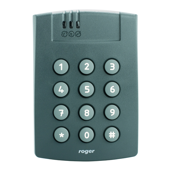
- Page 1 PRTxxMF series ISO/IEC 14443A and MIFARE readers Firmware version: x.35.164 Document version: Rev. H This document refers to following products: PRT12MF PRT12MF-BK PRT62MF PRT64MF PRT66MF Operating Manual...
-
Page 2: Table Of Contents
PRTxxMF series readers Operating Manual.doc 2019-01-29 1. GLOSSARY OF TERMS ................. 4 2. IMPORTANT NOTES ..................5 2.1. Compatibility Rules ........................... 5 2.2. About This Manual ..........................5 3. GENERAL DESCRIPTION ................6 3.1. Features ..............................6 3.1.1. General ..............................6 3.1.2. - Page 3 PRTxxMF series readers Operating Manual.doc 2019-01-29 5.7. Door Alarm ............................17 5.8. Tamper Alarm ............................. 18 5.9. Intruder Alarm ........................... 18 5.10. Duress Alarm ............................ 18 5.11. General Alarm ..........................18 5.12. Events Recording ........................... 18 5.13. Real Time Clock ..........................20 5.14.
-
Page 4: Glossary Of Terms
The procedure which clears contents of device’s memory and restores default (factory) settings. PRT Series Readers The PRT reader’s family developed and manufactured by Roger. Restart The situation when device goes through the initialization procedure, the same as when it is powered up. -
Page 5: Important Notes
Each PRTxxMF reader regardless of built-in keypad represents the same logical functionality. The only difference between various types of PRTxxMF series readers is limited to their mechanical construction, environment in which they can be installed and keypad which is available in some of readers. -
Page 6: General Description
3.1.2. Terminal Mode (Online Mode) 26/32/32 reversed/34/42/66 bit Wiegand data formats Magstripe data format (ABA Track II emulation) RACS CLK/DTA (for communication with Roger controllers) RS232, EPSO protocol RS232, direct output of cards and keys ... -
Page 7: Proximity Cards
For MSN number the MAD sector is using recommended type A key: A0A1A2A3A4A5. By default, reader uses MAD sector assigned by MSG organization to Roger company (Roger AID number: 5156). The PRTxxMF returns last seven bytes (56 bits) of the card number. Card number is transmitted starting from the MSB to LSB (reverse order) or from LSB to MSB (normal order) and if required supplemented with leading zeros. -
Page 8: Function Keys
3.3. F UNCTION Some of the PRTxxMF series readers are equipped with one or two function keys: [F1] with door bell icon and [F2] with the light bulb icon. The function of each function keys depends on the reader’s operating mode and its configuration. -
Page 9: Wiegand Formats
PRTxxMF series readers Operating Manual.doc 2019-01-29 4.1.1. Wiegand Formats When using Wiegand transmission format, data is send to the host using sequences of short pulses transmitted over CLK and DTA lines. Depending on the selected version of the transmission format, the reader can send 26, 32, 34, 42 or 66 bits to the host. -
Page 10: Rs232, Epso Protocol (9600, N, 8, 1)
PRTxxMF series readers Operating Manual.doc 2019-01-29 4.1.4. RS232, EPSO Protocol (9600, N, 8, 1) When programmed to this protocol reader operates in transaction mode, i.e. responds only to external commands received through the RS232 port. The software developer or system integrator must incorporate EPSO protocol into the host device (usually PC or microcontroller) to communicate with the reader. -
Page 11: Standalone Mode (Offline Mode)
PRTxxMF series readers Operating Manual.doc 2019-01-29 [*]: STX / 'A' / '#' / CR / LF / ETX [F1]: STX / 'C' / '#' / CR / LF / ETX [F2]: STX / 'D' / '#' / CR / LF / ETX 4.2. -
Page 12: Simple Standalone Mode
PRTxxMF series readers Operating Manual.doc 2019-01-29 4.2.2. Simple Standalone Mode The CLK and DTA lines may operate either as inputs or outputs. The function assigned to CLK or DTA line automatically defines whether this line will operate as output or input. If configured to be an output, the CLK or DTA line operates as an open collector line capable to sink up to 150 mA. -
Page 13: Managing Users
PRTxxMF series readers Operating Manual.doc 2019-01-29 switch reader between armed and disarmed modes, Programming they can have card and/or PIN. Note: All users can be programmed from RARC program as well. Note: MASTER and INSTALLER cards can be used as Programming Cards to start associated programming mode and to program reader based on multiple card readings method. -
Page 14: Arming Modes
PRTxxMF series readers Operating Manual.doc 2019-01-29 example when Facility Code is defined as “xxxx1ABxxx” then every card which has the same pattern is accepted by the reader regardless of the fact that it is not registered individually in reader’s memory. The positions marked with x are not analyzed for compliance with Facility Code. - Page 15 PRTxxMF series readers Operating Manual.doc 2019-01-29 Once accepted the reader grants you access (assuming that access is not disabled by option Access disabled when reader armed) and LED SYSTEM starts blinking When LED SYSTEM is blinking, once again present your TOGGLE card ...
- Page 16 PRTxxMF series readers Operating Manual.doc 2019-01-29 When using proposed configuration the current arming mode of the reader is controlled by the alarm system (output line from alarm system controls reader’s arming state), as a result reader always operates in the same arming mode as alarm system. Using TOGGLE or TOGGLE LTD card/PIN users can “request”...
-
Page 17: Door Bell Function
PRTxxMF series readers Operating Manual.doc 2019-01-29 5.5. D UNCTION By default the [F1]: Door Bell and [F2]: Light Bulb keys operate as door bell buttons. When pressed they produce continues sound generated by the internal buzzer and optionally can trigger the [47]: Door Bell output (if programmed). -
Page 18: Tamper Alarm
PRTxxMF series readers Operating Manual.doc 2019-01-29 Pause - 5 s valid identifier disappears automatically after 3 minutes. Also, closing door immediately clears this alarm. Note: Modulation methods are used for both, the output line and for internal buzzer as well (if configured for alarm indication). - Page 19 PRTxxMF series readers Operating Manual.doc 2019-01-29 Access granted – Facility Access has been granted for card with valid Facility Code Code Access denied Access for the user (ID + name) has been denied Access denied – Facility Access has been denied for card with valid Facility...
-
Page 20: Real Time Clock
PRTxxMF series readers Operating Manual.doc 2019-01-29 Tamper Alarm Reader entered Tamper Alarm state Intruder Alarm Reader entered Intruder Alarm state Duress Alarm Reader entered Duress Alarm state Unknown event Event code doesn’t fit any known event – error in data 5.13. -
Page 21: Optical And Acoustic Signals
PRTxxMF series readers Operating Manual.doc 2019-01-29 Intruder Alarm 60 min Defines duration time Intruder Alarm. Programming timer to 00s makes that timer (00-99 sec./min.) counts down for unlimited period till moment when reader changes it arming mode. General Alarm 3 min... -
Page 22: Operation With Xm-2 I/O Extension Module
PRTxxMF series readers Operating Manual.doc 2019-01-29 Acoustic Signals Signal Symbol Description One long signal Error - unknown identifier, access denied. Three short * * * Command successfully completed (OK signal). beeps Two short beeps Prompt signal, the reader is waiting for the next part of the command to be entered. -
Page 23: Programming Of Readers Without Keypad
PRTxxMF series readers Operating Manual.doc 2019-01-29 Preparing the Reader for Standalone Mode (Offline mode) If the unit is dedicated to Standalone Mode (autonomic operation) then programming procedure must be followed: 1. Configure the reader to either Full or Simple Standalone Mode operating mode and program MASTER and INSTALLER cards and/or PIN-s (Memory Reset) 2. -
Page 24: Programming Via Memory Card
M-Card to the reader or to the RARC program. Note: The communication between RARC program and Memory Card can be provided through any PRTxxMF series reader connected to the PC. The entire settings of the reader can be divided into three parts: ... -
Page 25: Exporting Users Data To Memory Card
PRTxxMF series readers Operating Manual.doc 2019-01-29 Read the MASTER card or enter MASTER PIN, reader will enter User Programming Mode (LED STATUS is red, LED OPEN (green) is on) Read the M-Card (just close it to the reader and take it back), reader will generate OK... -
Page 26: Memory Reset
PRTxxMF series readers Operating Manual.doc 2019-01-29 6.3. M EMORY ESET The Memory Reset is a procedure which erases reader’s memory (all cards, all PIN-s including MASTER and INSTALLER users) and restores factory default settings. It also enables programming of operating mode and MASTER as well as INSTALLER identifiers (if required). Additionally it enables configuration of IN1 and IN2 inputs in Wiegand and Magstripe Terminal modes. -
Page 27: Operating Modes
PRTxxMF series readers Operating Manual.doc 2019-01-29 Note: If in the step 6 no function is selected within 9 s or both steps are skipped with # key then Memory Reset is completed with default settings i.e. IN1=[29] and IN2=[28]. It is forbidden to assign the same functions to both inputs except for the function [11]. - Page 28 PRTxxMF series readers Operating Manual.doc 2019-01-29 Online mode, RS232, PINs Reader is connected to the host through RS232 transmitted as whole numbers (9600,N,8,1) serial interface. Each key entry is buffered, once the [#] key is pressed reader transmits entire PIN code as a single number max 16 digits long.
- Page 29 PRTxxMF series readers Operating Manual.doc 2019-01-29 1-10 digits long PIN, Each key pressed is buffered in reader’s memory; with a press of a [#] transmitted key reader transmits entire PIN code. The PIN code is transmitted as a format BCD coded number.
-
Page 30: Installer Programming
PRTxxMF series readers Operating Manual.doc 2019-01-29 11010010 11000011 10110100 10100101 10010110 10000111 01111000 01101001 01011010 01001011 00111100 00101101 Table B: 4-bit key coding ASCI 0000 0001 0010 0011 0100 0101 0110 0111 1000 1001 1010 1011 8 . I N S T A L L E R R O G R A M M I N G Use this mode to configure various functionalities of the reader. - Page 31 PRTxxMF series readers Operating Manual.doc 2019-01-29 This EF digits define the function for CLK line (when reader is configured for Simple Standalone Mode) or for REL1 output on XM-2 expander (when reader is configured for Full Standalone Mode). The CLK line can operate as input or output while REL1 always works as output. For I/O function codes see section Input/Output Functions.
- Page 32 PRTxxMF series readers Operating Manual.doc 2019-01-29 [65][J] – Programming option “Enable Card/PIN reading when Prealarm”, J=0..1, default: J=0 When J=0 then the option is disabled and reader will not read cards nor PIN-s when it is in Prealarm state, when J=1 reader will allow to use cards/PIN-s during Prealarm state.
- Page 33 PRTxxMF series readers Operating Manual.doc 2019-01-29 This timer defines time for which LED STATUS will be on after arming mode is changed. Program S=0 for seconds or S=1 for minutes. Setting S=0 and KL=00 or S=1 and KL=00 is forbidden.
-
Page 34: Input/Output Functions
PRTxxMF series readers Operating Manual.doc 2019-01-29 This timer defines duration time for pulse generated on [53] function output. Program S=0 for seconds or S=1 for minutes. [85][S][KL] – Programming “Pulse on Arming/Disarming” timer, S=0..1, KL=01..99, default: S=0 KL=02 This timer defines duration time for pulse generated on [54] function output. Program S=0 for seconds or S=1 for minutes. - Page 35 PRTxxMF series readers Operating Manual.doc 2019-01-29 Unlock Time. It is not activated when access is granted from secondary reader. This output is dedicated for rotary gates when opening outputs (for clockwise anticlockwise movement) are necessary Entry Door Lock Output, triggered whenever access is granted from secondary (external) reader, this output goes on for time specified by Door Unlock Time.
-
Page 36: User Programming
PRTxxMF series readers Operating Manual.doc 2019-01-29 mode again. General Alarm Output, line is triggered in the moment when Tamper Alarm or Intruder Alarm is raised. Output remain active for a time defined by General Alarm Timer however whenever reader changes its arming mode this output is immediately cleared. - Page 37 PRTxxMF series readers Operating Manual.doc 2019-01-29 added with this function are stored in unoccupied (free) location of the memory i.e. with unknown IDs. [13][ID][PIN][#][Card] – Add NORMAL user with ID, PIN and card The new NORMAL user is registered in the memory at the location indicated by his ID number (ID=000–119).
-
Page 38: Programming From Pc
PRTxxMF series readers Operating Manual.doc 2019-01-29 The reader searches its memory for the presented card. Once successful it removes it from the memory and the record previously occupied by this card is released. This command removes only card, if the user has PIN then it still can be used. - Page 39 PRTxxMF series readers Operating Manual.doc 2019-01-29 Note: For programming purpose CLK, DTA and RTS lines must be disconnected from host devices if they were earlier connected. 10.2. P RUD-1 ROGRAMMING VIA INTERFACE In this scenario connection between programmed reader and the PC is made through dedicated RUD-1 interface which is also used to power supply programmed reader (no extra source of power is required).
- Page 40 Customers are kindly advised to register at the website so that Roger can send information as soon as new firmware versions is ready for download. Firmware can be uploaded to reader via ordinary RS232 COM port or RUD-1 (USB) interface. In both cases RogerISP 4 program is required.
- Page 41 PRTxxMF series readers Operating Manual.doc 2019-01-29 Note: Once the firmware upgrade is accomplished but programmed device doesn’t work then it may be necessary to start Memory Reset procedure and/or upload the firmware once more. 10.3.1. Firmware upgrade via RS232 COM port ...
- Page 42 PRTxxMF series readers Operating Manual.doc 2019-01-29 1 1 . N S T A L L A T I O N U I D E L I N E S Reader should be installed in such way as to ensure physical access to the connection cable, screw terminals and programming jumpers.
- Page 43 PRTxxMF series readers Operating Manual.doc 2019-01-29 With its relatively weak electromagnetic field generation, reader should not cause any harmful interference to operation of other equipment. However, its card reading performance can be affected by other interference generating devices, especially radio waves emitting equipment or CRT computer monitors.
- Page 44 PRTxxMF series readers Operating Manual.doc 2019-01-29 Violet RTS line for RS232 +12V Supply input plus Black Supply input minus, also reference ground for RS232 Grey TAMP Tamper switch contacts, normally closed, isolated, IP67, 24V/50mA. Contact becomes open when unit is detached from the place of installation or upper White part of enclosure is open.
- Page 45 PRTxxMF series readers Operating Manual.doc 2019-01-29 Weight PRT12MF/PRT12MF-BK: 150g PRT62MF: 100g PRT64MF: 120g PRT66MF: 120g Approvals Ordering Codes PRT12MF Outdoor proximity reader with keypad, laser engraved long durability silicon rubber keypad, two function keys, dark grey ABS enclosure, pig-tail cable...
- Page 46 PRTxxMF series readers Operating Manual.doc 2019-01-29 User List Reader name: Reader location: Card code Type User Name None MASTER None INSTALLER 46/54...
- Page 47 PRTxxMF series readers Operating Manual.doc 2019-01-29 47/54...
- Page 48 PRTxxMF series readers Operating Manual.doc 2019-01-29 48/54...
- Page 49 PRTxxMF series readers Operating Manual.doc 2019-01-29 49/54...
- Page 50 PRTxxMF series readers Operating Manual.doc 2019-01-29 50/54...
- Page 51 PRTxxMF series readers Operating Manual.doc 2019-01-29 51/54...
- Page 52 PRTxxMF series readers Operating Manual.doc 2019-01-29 52/54...
- Page 53 PRTxxMF series readers Operating Manual.doc 2019-01-29 53/54...
- Page 54 PRTxxMF series readers Operating Manual.doc 2019-01-29 This symbol placed on a product or packaging indicates that the product should not be disposed of with other wastes as this may have a negative impact on the environment and health. The user is obliged to deliver equipment to the designated collection points of electric and electronic waste.
Need help?
Do you have a question about the PRTxxMF Series and is the answer not in the manual?
Questions and answers