
Subscribe to Our Youtube Channel
Related Manuals for Stanford Research Systems BJT SIM911


Summary of Contents for Stanford Research Systems BJT SIM911
- Page 1 Operation and Service Manual BJT Preamp SIM911 Stanford Research Systems Revision 2.1 May 8, 2007...
- Page 2 (1) year from the date of shipment. Service For warranty service or repair, this product must be returned to a Stanford Research Systems authorized service facility. Contact Stanford Research Systems or an authorized representative before returning this product for repair.
-
Page 3: Table Of Contents
Contents General Information Safety and Preparation for Use ....Symbols ......Notation . - Page 4 Contents SIM911 BJT Preamp...
-
Page 5: General Information
General Information The SIM911 BJT Preamp, part of Stanford Research Systems’ Small Instrumentation Modules family, is a low noise general purpose volt- age preamplifier with bandwidth from DC to 1 MHz. Safety and Preparation for Use Biomedical Applications Under certain conditions, the SIM911 may prove to be unsafe for applications involving human subjects. -
Page 6: Symbols
General Information Symbols you may Find on SRS Products Symbol Description Alternating current Caution - risk of electric shock Frame or chassis terminal Caution - refer to accompanying documents Earth (ground) terminal Battery Fuse On (supply) Off (supply) SIM911 BJT Preamp... -
Page 7: Notation
General Information Notation The following notation will be used throughout this manual: A warning means that injury or death is possible if the instructions WARNING are not obeyed. A caution means that damage to the instrument or other equipment CAUTION is possible. -
Page 8: Specifications
General Information Specifications Performance Characteristics Frequency range DC to 1 MHz; 3 dB @ 1.9 MHz, typ. Gain 1, 2, 5, 10, 20, 50, 100 Gain accuracy 0.5 % DC to 100 kHz 5 % @ 1 MHz, typ. Gain stability 200 ppm C Input voltage noise (RTI, gain 1.8 nV... -
Page 9: Operation
1 Operation The SIM911 BJT Preamp is a flexible low noise voltage preamplifier for general use from DC to 1 MHz. This chapter gives the necessary information to get started quickly with the SIM911. In This Chapter 1.1 Instrument Overview ....1 – 2 Front Panel Operation . -
Page 10: Instrument Overview
1 – 2 Operation 1.1 Instrument Overview The SIM911 is a voltage preamplifier with low input and output noise. It provides selectable gain from 1 to 100 of a single ended or true di erential signal. The amplifier runs from DC to 1 MHz, or can be AC coupled with 0.7 Hz 3dB frequency. -
Page 11: Gain
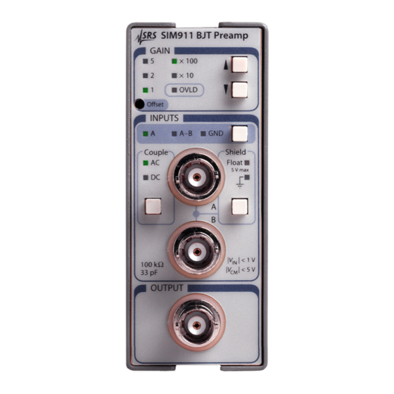
1.2 Front Panel Operation 1 – 3 gain settings, the overload light, the input settings, the coupling and the shield states, and the buttons to control them. Figure 1.2: The SIM911 front and rear panel. 1.2.1 Gain The gain is selectable from 1 to 100. Gain settings are 1, 2, 5, 10, 20, 50, and 100 and are displayed as a product of 1, 2, or 5 and a multiplier of 10 or 100. -
Page 12: Inputs
1 – 4 Operation greater than 1 V, or the output is outside 10 V. The overload signal can also be asserted on the status pin. See section 2.4.5. 1.2.4 Inputs The two input connectors, labeled A and B, are in the INPUT block of the front panel. -
Page 13: Rear Panel Output
1.3 Rear Panel Output 1 – 5 1.3 Rear Panel Output The rear panel contains a BNC connected to the output, and the SIM interface connector (see Figure 1.2). The rear panel output is wired in parallel to the front panel output. The output is not designed to drive 2 simultaneous 50 loads. -
Page 14: Sim Interface
1 – 6 Operation 1.4 SIM Interface The primary connection to the SIM911 BJT Preamp is the rear-panel DB–15 SIM interface connector. Typically, the SIM911 is mated to a SIM900 Mainframe via this connection, either through one of the internal mainframe slots, or the remote cable interface. It is also possible to operate the SIM911 directly, without using the SIM900 Mainframe. - Page 15 1.4 SIM Interface 1 – 7 The mating connector needed is a standard DB–15 receptacle, such as Amp part # 747909-2 (or equivalent). Clean, well-regulated supply voltages of 5, 15 VDC must be provided, following the pin-out specified in Table 1.1. Ground must be provided on pins 1 and 8, with chassis ground on pin 9.
- Page 16 1 – 8 Operation more about grounding The Chassis Ground and Power Ground are tied together in the in- strument. The 5 V sections use the Power Ground, and the signal sections of the instrument use the 15 V and Signal Ground. The Signal Ground and Power Ground are tied through protection schot- tky diodes, and can therefore not be more than 0 35 V apart.
-
Page 17: Remote Operation
2 Remote Operation This chapter describes operating the module over the serial interface. In This Chapter 2.1 Index of Common Commands ... . . 2 – 2 Alphabetic List of Commands ... . . 2 – 3 Introduction . -
Page 18: Index Of Common Commands
2 – 2 Remote Operation 2.1 Index of Common Commands symbol definition Integers Required for queries; illegal for set commands Required parameter for set commands; illegal for queries Amplifier *RST 2 – 6 Reset GAIN(?) i 2 – 6 Gain COUP(?) i 2 –... -
Page 19: Alphabetic List Of Commands
2.2 Alphabetic List of Commands 2 – 3 2.2 Alphabetic List of Commands *IDN? 2 – 8 Identify *RST 2 – 6 Reset *SRE(?) i 2 – 7 Service Request Enable *STB? 2 – 7 Status Byte *TST? 2 – 8 Self Test CONS(?) i 2 –... -
Page 20: Introduction
2 – 4 Remote Operation 2.3 Introduction Remote operation of the SIM911 is through a simple command lan- guage documented in this chapter. Both set and query forms of most commands are supported, allowing the user complete control of the amplifier from a remote computer, either through the SIM900 Main- frame or directly via RS-232 (see Section 1.4.2.1). -
Page 21: Commands
2.4 Commands 2 – 5 2.4 Commands This section provides syntax and operational descriptions for remote commands. 2.4.1 Command syntax The four letter mnemonic (shown in CAPS) in each command se- quence specifies the command. The rest of the sequence consists of parameters. -
Page 22: Amplifier Commands
2 – 6 Remote Operation 2.4.4 Amplifier commands These commands provide control over the settings of the amplifier circuitry. All of these commands are persistent, in the sense that the module will restore the last amplifier configuration upon power-on reset. *RST Reset Reset the amplifier to default configuration. -
Page 23: Status Commands
2.4 Commands 2 – 7 2.4.5 Status commands The Status commands query and configure registers associated with status reporting of the SIM911. *STB? Status Byte Reads the Status Byte register. Execution of the *STB? query clears all flag bits set in the Status Byte register (see the Register Model section 2.5 for more about the Status Byte register). -
Page 24: Interface Commands
None of these commands have any e ect on the amplifier function itself. *IDN? Identify Query the device identification string. The identification string is formatted as: Stanford Research Systems,SIM911,S/N******,VER#.## where ****** is the 6-digit serial number, and #.## is the firmware revision level. Example: *IDN? Stanford Research Systems,SIM911,s/n003654,ver2.10... -
Page 25: Register Model
2.5 Register Model 2 – 9 2.5 Register Model The SIM911 monitors and reports errors and other conditions using a single 8-bit register, the Status Byte register. Each bit in the register is mapped to a particular event category, and if that event occurs the corresponding bit is set to 1. -
Page 26: Service Request Enable (Sre)
2 – 10 Remote Operation 2.5.2 Service Request Enable (SRE) The SRE is used to control the status line when Status-Monitors- Overload Mode is disabled (See STOL). This is an 8-bit wide register. Each bit in the SRE corresponds one-to- one with a bit in the SB register, and acts as a bitwise AND of the SB flags. -
Page 27: Performance Tests
3 Performance Tests This chapter describes how to adjust the module to meet it’s speci- fications. The module should be warmed up for at least 15 minutes before making any adjustments. In This Chapter 3.1 O set ......3 – 2 Calibration . -
Page 28: Calibration
3 – 2 Performance Tests 3.1 Offset The SIM911 front-panel o set adjustment provides an easy way for the user to null the amplifier’s DC o set. The module should be run- ning for at least 15 minutes before setting the o set. To do this, set the input to GND. -
Page 29: Performance Tests
3.3 Performance Tests 3 – 3 3.2.3 Adjusting the freq adjust The clocking of the microprocessor is done by an RC oscillator, which must be adjusted to 1% of 2.5 MHz in order to insure the serial baud rate is 9600 baud. This is done with the ”Freq Adjust” trimcap (C402). -
Page 30: Sim911 Performance Test Record
3 – 4 Performance Tests your signal reference. See table 1.1 for the power and communication connector pin specifications. 3.4 SIM911 Performance Test Record Description Measured Value Serial Number Clock Frequency at TP401 Gain 1 Gain 2 Gain 5 Gain 10 Gain 20 Gain 50 Gain 100... - Page 31 4 Parts Lists and Schematics This chapter presents a brief description of the SIM911 circuit design. A complete parts list and circuit schematics are included. In This Chapter 4.1 Circuit Discussion ....4 – 2 4.1.1 Input amplifier and protection circuitry .
-
Page 32: Circuitry
4 – 2 Circuitry 4.1 Circuit Discussion 4.1.1 Input amplifier and protection circuitry The front-end amplifier Q102 is a matched transistor pair biased with 3 mA per side. Closed-loop feedback is provided by U105 for an overall first-stage gain of 10. The MAT02 is run at this collector current to optimize input voltage noise. - Page 33 4.1 Circuit Discussion 4 – 3 ensure that no “runt” clock pulses are produced that would violate U405’s minimum clock periods. Four separate clock-starting signals are combined by U402: Power-on reset Amplifier overload Incoming serial data Front-panel button press The fast start-time of the RC-oscillator ensures that incoming se- rial data will be correctly decoded by the microcontroller’s UART, even when the clock is started by the serial start bit of the incoming data.
-
Page 34: Parts List
4 – 4 Circuitry 4.2 Parts List Reference SRS P/N Part Value Reference SRS P/N Part Value C103,C109,C111,C113,C202, 5-00319 10U-35V R125 4-01134 1.50K C204,C206,C208,C213,C215, R126,R127,R205,R206,R212, 4-01431 C217,C219,C404,C406,C408 R213,R221,R222,R223,R224 C104,C106,C108,C110,C112, 5-00299 0.1U R128,R129 4-00142 100K C116,C117,C201,C203,C205, R130,R131,R412,R414 4-01455 C207,C212,C214,C216,C218, R132,R302,R303,R304,R305, 4-01471 C403,C405,C407,C411,C412, R306,R307,R308,R309,R310, C413,C414,C415,C416...
Need help?
Do you have a question about the BJT SIM911 and is the answer not in the manual?
Questions and answers