Table of Contents
Advertisement
Quick Links
Advertisement
Table of Contents

Related Manuals for Barry-Wehmiller Streamfeeder Value Series


Summary of Contents for Barry-Wehmiller Streamfeeder Value Series
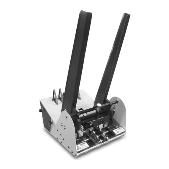
- Page 1 Value Series V-710IJ Manual...
- Page 2 Part Number: 00900367 © 2009 Thiele Technologies, Inc. - Streamfeeder. All rights reserved. No part of this publication may be reproduced, photocopied, stored on a retrieval system, or transmitted without the express written consent of Thiele Technologies, Inc. - Streamfeeder. Thiele Technologies, Inc.
-
Page 3: Table Of Contents
ontents Safety Information ............ii Specifications ..............iv Section 1: About the Machine ............1 Section 2: Installing the Machine ..........5 Section 3: Preparing for Operation ..........11 Section 4: How to Operate ............19 Section 5: Troubleshooting ............23 Section 6: Inspection and Care ...........25 Section 7: Mechanical Components ...........31 Section 8: Electrical Components ..........46 V-710iJ M alue erieS anual... - Page 4 efore egin Message Conventions DANGER signifies an action or specific equipment area that can result in serious injury or death if proper precautions are not taken. WARNING signifies an action or specific equipment area that can result in personal injury if proper precautions are not taken. CAUTION signifies an action or specific equipment area that can result in equipment damage if proper precautions are not taken.
- Page 5 efore egin Message Conventions Avoid injury. Do not reach around guards. Hazardous voltage. Contact will cause electric shock or burn. Turn off and lock out power before servicing. Moving parts can crush and cut. Keep guards in place. Lock out power before servicing.
-
Page 6: Specifications
peCifiCations Maximum Product Size: ......12 W x 12 L in (305 x 305 mm)* Minimum Product Size: ......3.75 W x 3.75 L in (95 x 95 mm) Optional: ........... 2.5 W x 2.5 L in (63 x 63 mm) Min/Max Product Thickness: ....... -
Page 7: About The Machine
About the Machine Features The V-710IJ Universal Friction Feeder is designed for reliability, flexibility, and ease of use with a variety of vacuum and non-vacuum bases. All parts required for setup, loading, feeding, and easy operator con- trol are combined into one compact unit. Review the main assemblies in Figure 1-1 to become familiar with names and locations of feeder parts and adjustments. - Page 8 Product Description Section 1 Table 1-1. Main Assemblies Feature Descriptions Feature Description Gate assembly and adjustment Mounted on a gate bracket assembly above the feed belts, this device provides a curvature to help preshingle stacked material. When properly adjusted, a clearance is created to help singulate and feed material. Table top Used to support the back wedge.
- Page 9 Control Panel Components Figure 1-2A. Control Panel Components (Left and Right Side Views) Figure 1-2B. Control Panel Components (End View) V-710iJ M alue erieS anual...
- Page 10 Table 1-2. Control Panel Feature Descriptions Feature Description External run input connector This 4-pin connector (labeled External Run Input) is used to carry start/ (optional) stop signals from a vacuum or non-vacuum base to the feeder. Power On/Off Toggles AC power On or Off. Fuse holder Contains two replaceable 5-Amp, 5x20 mm time delay fuses. IMPORTANT: Always make sure power module is replaced exactly as removed so that “115”...
-
Page 11: Installing The Machine
Installing the Machine This section provides information on installing the V-710IJ Universal Friction Feeder onto a vacuum or non-vacuum transport base. Information for a particular application typically includes procedures When performing initial installation, always for basic parts removal, feeder mounting and alignment, and cable make sure you turn Off the main power switch and disconnect all equipment from the connections for power and control interface. - Page 12 1. Loosen locking knobs at both side guides (Figure 2-1). STEP 1: 2. Slide each side guide to the outermost position. Do not lock in Repositioning Front place. Side Guides Front side guides Locking knob Figure 2-1. Front Side Guides Being Repositioned STEP 2: 1.
- Page 13 STEP 3: 1. Locate the gate adjustment knobs (Figure 2-3) and turn com- pletely in a clockwise direction to raise hopping rollers. Raising Hopping Rollers 2. Then, locate the vertical adjustment lever on the hopping roll- ers assembly and push down all the way. This will raise the feed rollers to highest vertical position possible, thus making for maximum clearance.
- Page 14 1. Lift the feeder onto the top plate of the vacuum base and slide STEP 5: forward toward the vacuum base gate. Initial Positioning 2. Center the feeder between the two side guides as you posi- of Feeder tion the feeder fully forward. To verify centering, sight down the center of the feeder gate, making sure it is in-line with the vacuum base gate (Figure 2-5).
- Page 15 Using the two-wire interface cable supplied for vacuum base applica- STEP 7: tions: Connecting 1. At the feeder, connect external run input cable to feeder using External Run Input the two-pin threaded connector on the control panel. 2. At the vacuum base, open access door at end of the lower enclosure to locate start/stop control circuit (Figure 2-6).
- Page 16 STEP 8: Leading edge Checking Material 2 / 3 should be into transfer section Discharge from Feeder (continued) Figure 2-7. Checking for Proper Material Discharge from Feeder to Vacuum Base 4. Check to make sure the material is still under the hold-down roller bearings and also resting on the vacuum base transfer section.
-
Page 17: Preparing For Operation
Preparing for Operation Once the Streamfeeder V-710IJ Universal Friction Feeder is installed on your host system, you are then ready to prepare the machine for operation. To do so, you must perform several adjustments with the When performing initial feeder adjustments material you are going to be feeding. And, you must do a test run with prior to operation, always make sure you turn this material to verify that it is set correctly before you begin cycling Off the main power switch and disconnect all... - Page 18 STEP 1: Procedure To adjust the gate assembly for proper gap: Gate Assembly Adjustment 1. Slide a single sheet of test product under the gate assembly. It may be necessary to pull up on the adjustment knob to allow the piece to be inserted. 2.
- Page 19 STEP 1: To adjust the gate for effective material skew control, follow these Gate Assembly steps: Adjustment 1. Repeat drag test detailed on page 12. (continued) 2. Test the piece for uneven side-to-side drag. Grasp with two hands and slide it front-to-back under the gate assembly. A NO TE proper adjustment allows for equal drag on the left and right sides of the piece of material.
- Page 20 Changing From Procedure Certain types of material may demand that you change the gate Factory Set assembly from a high-tension setting to a low-tension setting (for High-Tension to example, irregular shaped material). Low-Tension To change the spring from a high to a low tension, follow these steps: 1.
- Page 21 STEP 2: Dual-Knob Side Guides. To adjust each side guide for proper offset horizontal spacing using the dual-knob adjustment, follow these steps: Side Guides Setting 1. Start by loosening each side guide wing adjuster (counter-clock- wise) This will allow you to move each side guide as needed. 2.
- Page 22 STEP 3: Procedure To adjust the back wedge for initial proper positioning, follow these Back Wedge steps: Adjustment 1. Grasp a handful of material, approximately 2 to 2.5 in. (5 to 6 cm) thick, and preshingle the edges with your thumb. 2. Place the preshingled material in the hopper so that the edges rest against the curvature of the gate assembly.
- Page 23 STEP 4: Now that you have made all the necessary adjustments for operation, it is recommended that you verify material singulation and separation Verifying Proper at the feeder for your particular application. Before you power-up and Installation run your machine with a full hopper, manually feed several sheets of material through the gate assembly area.
- Page 24 Notes V-710iJ M alue erieS anual...
-
Page 25: How To Operate
How to Operate This section provides a sequence of operation for the V-710IJ Univer- sal Friction Feeder. It also provides information for clearing a jam and for shutdown. Sequence of Successful power-up and operation is assured if you apply the follow- ing sequence of steps: Operation 1: Loading material in the hopper 2: Determining stack height... - Page 26 Section 4 Troubleshooting STEP 3: Turn the feeder power On by pushing the horizontal line (—) at the Power On/Off rocker switch. Powering On Feeder • For feeders equipped with an extenal run option, feeder motor will not run until the entire base power switch is turned On (feeder On/Off is controlled via external run input cable).
- Page 27 Clearing a Jam If a jam occurs during operation, follow these steps: 1. Turn the feeder power Off by pushing the circle (O) at the rocker Power On/Off rocker switch. 2. Remove jammed product from feeder. While doing so, try to determine the cause of the jam (see Section 5, “Troubleshoot- ing”).
- Page 28 Notes V-710iJ M alue erieS anual...
-
Page 29: Troubleshooting
Troubleshooting Table 5-1 is intended to provide you with quick solutions to the more common day-to-day problems you may encounter. Table 5-1. Quick-Look Troubleshooting Problem Cause Solution No AC power to Move switch to "On" (or "—" position). 1. On/Off switch in "Off" (or "O" position). feeder Check and secure power cord at AC 2. - Page 30 Table 5-1. Quick-Look Troubleshooting (continued) Problem Cause Solution Feed belts are Review gate assembly adjustment 5. Gate assembly may be down too tight. operating, but ma- procedure. terial not feeding (continued) Remove material from stack. Test 6. Too much weight in hopper. again. Feed belt(s) not Reduce weight. Test again. 1. Excessive weight in hopper. tracking on rollers 2.
-
Page 31: Inspection And Care
Inspection and Care Please read this Section to learn how to: • Visually inspect your machine to detect part problems which may require adjustment or replacement. When performing initial feeder adjustments • Periodically care for your machine to prevent any operational prob- prior to operation, always make sure you turn Off the main power switch and disconnect all lems. - Page 32 Visual Inspection Ensuring Proper Feed and Discharge Belt Tracking (continued) Check for visual signs of: • Stretching. • Improper roller adjustment. Ensuring Proper Timing and Drive Belt Tracking Check for visual signs of: • Misaligned timing pulleys. Checking for Gate Assembly Wear Check for visual signs of wear: • Advancing O-ring, or standard O-ring: Flat areas along the O-rings.
- Page 33 Visual Inspection Advancing O-Ring Gate: Adjusting Worn O-Rings (continued) To adjust worn O-rings on advancing O-ring gate: 1. Turn Off feeder and remove power cord from outlet. 2. Rotate O-rings by grasping advance knob and pushing to- wards gate cylinder about .125 to .25 in. (3 to 6 mm). NOTE: O-rings only advance when pushing toward gate cylinder.
- Page 34 Preventive Care Cleaning Feed and Discharge Belts To clean feed belts: 1. Turn Off feeder and remove power cord from outlet. 2. Remove gate assembly and safety shields from gate plate for Use only isopropyl alcohol. Other solvents can easier access to belts. cause belts to wear prematurely, and even cause 3.
- Page 35 Preventive Care Cleaning Gate Assembly Use only isopropyl alcohol (98% concentration). Do not use any (continued) other types of solvents. They can cause premature wear of the belts, or even total breakdown of the material. To clean gate assemblies: 1. Turn Off feeder and remove power cord from outlet. NO TE 2.
- Page 36 Notes V-710iJ M alue erieS anual...
-
Page 37: Mechanical Components
Mechanical Components V-710iJ M alue erieS anual... - Page 38 1: TRIANGLE WEDGE ASSEMBLY #63311018 DIAGRAM PART NUMBER DESCRIPTION NUMBER Wedge Guide Shaft 44633018 SHCS 10-32 X 5/8” LG 00002320 Wedge Block 44633014 T-Nut Round 44633016 Knob 3 Lobe 10-32 X 5/8” LG 44633033 Ring Grip 3/8 Waldes 00001110 Wedge Material Support 43560212 2: GATE PLATE ASSEMBLY #84111006...
- Page 39 DIAGRAM PART NUMBER DESCRIPTION NUMBER Lever Adjustment 10-32 X .75 43555098 Side Guide Adjust Clamp Front 44675006 Lower Gate Support Bar 44841005 Gate J Hook 44841011 SHCS 8-32 X 5/8” LG 00002215 Upper Gate Support 44841006 Side Guide Adjust Clamp Rear 44841004 Pregate Bar 44841007...
- Page 40 3: SIDE GUIDE KIT 1424 TEFLON ASSEMBLY #10501108 DIAGRAM PART NUMBER DESCRIPTION NUMBER 3-1 1 Side Guide Right 1424 Teflon 51050040 Label Warning 44600005 3-2 1 Side Guide Left 1424 Teflon 51050039 Label Warning 44600005 Screw FHS 10-32 X 1/2” LG 00002330 Guard Rear Accordion 44600001 4: ADVANCING O RING GATE w/HORIZON ADJUST V-710iJ M alue erieS...
- Page 41 V-710iJ M alue erieS anual...
- Page 42 ASSEMBLY #87211001 DIAGRAM PART NUMBER DESCRIPTION NUMBER Handle Studded 10-32 X 1/2” 44657007 BHCS 8-32 X 1/2” LG 00002302 Spacer Belt Indexer .312 X .375 44657010 Screw Shoulder 8-32 Slotted 00003320 Screw Shoulder 8-32 X 1/8 00003321 Belt Indexer Bracket 44657005 Pinch Roll Cam 44657003...
- Page 43 V-710iJ M alue erieS anual...
- Page 44 5: HOLD DOWN ASSEMBLY #10501109 DIAGRAM PART NUMBER DESCRIPTION NUMBER Discharge Roller Collar 51277087 E-Clip 3/8 00001150 R6 Bearing 23500095 Hold Down Shaft 51050238 Spring Pin 1/8” 51312003 Hold Down Spring 51328001 FHSC 10-32 X 3/8” 00002234 Hold Down Mount 51312001 Hold Down Block 51050239...
- Page 45 V-710iJ M alue erieS anual...
- Page 46 6: GROOVED GUM CARRIAGE ASSEMBLY #10501105 DIAGRAM PART NUMBER DESCRIPTION NUMBER Adjustable Roller Shaft 44841020 Roller Crown Driven Narrow 44841033 Bearing Ball R8 23500094 Clip E 1/2 Waldes 00001155 Knob 3 Arm 10-32 X 7/16 23500092 Idler Shaft 43555047 Tube Driven 44630004 Bearing Ball R8 23500094...
- Page 47 6: GROOVED GUM CARRIAGE (CONTINUED) ASSEMBLY #10501105 DIAGRAM PART NUMBER DESCRIPTION NUMBER 6-14 Upper Discharge Shaft 51050008 Holder Outboard Bearing Cup 23500032 Drive Crown Roller 51050006 Roller Crown Driven Narrow 44841033 Pulley 20T 1/2 Bore w/Flange Driven 23500097 Bearing Ball R8 23500094 Clip E 1/2 Waldes 00001155...
- Page 48 7: EXTERIOR FEATURES DIAGRAM PART NUMBER DESCRIPTION NUMBER Knob Straight Knurl Black 44675030 Shell Split Back 44841060 Spacer Shield 51050073 Shell Split Front Ear Right 51050102 Shield Lexan Smoked 51050072 Label Warning Roller Pinch Point 44600004 BHCS 10-32 X 2” LG 00003396 Discharge Support Bar 44841035...
- Page 49 V-710iJ M alue erieS anual...
- Page 50 8: INTERIOR FEATURES DIAGRAM PART NUMBER DESCRIPTION NUMBER SCR Board w/36 Inch Pot Leads 44642025 Plate Mounting SCR 51050112 Board V710 IJ Control (115V Models Only) 44841015 Board V710 IJ Control (230V Models Only) 51050171 Speed Pot Assembly 10501137 Line Filter Assembly 10501138 Standoff Fem/Fem 5/16 Hex 8-32 x 1-5/16 AL 51050115...
- Page 51 V-710iJ M alue erieS anual...
-
Page 52: Electrical Components
Electrical Components V-710iJ M alue erieS anual... - Page 53 V-710iJ M alue erieS anual...
- Page 54 V-710iJ M alue erieS anual...
- Page 55 V-710iJ M alue erieS anual...
- Page 56 Notes V-710iJ M alue erieS anual...
- Page 58 © 2009 Thiele Technologies, Inc. - Streamfeeder Printed in the USA.
Need help?
Do you have a question about the Streamfeeder Value Series and is the answer not in the manual?
Questions and answers