Table of Contents
Advertisement
Quick Links
Advertisement
Table of Contents

Related Manuals for AUDAC SMQ


Summary of Contents for AUDAC SMQ
- Page 1 SMA & SMQ User Manual www.audac.eu...
- Page 2 Index Introduction Precautions Safety requirements Caution servicing EC Declaration of Conformity Waste of Electrical and Electronic Equipment (WEEE) Caution Chapter 1: Pin connections and connectors Connection standards Wire up the system Chapter 2: Front & rear panel Front panel overview Front panel description Rear panel overview Rear panel description...
-
Page 3: Table Of Contents
Chapter 5: Configuring the amplifier Menu structure overview Main screen Settings menu Level Input Mute Output setup Filters Equalizing Delay Max level Standby Limiter Dynamic bass Bridge Clear presets General setup Input gain Password Info Temperature Factory reset Save Lock Chapter 6: Additional information Technical specifications... - Page 4 Introduction WaveDynamics™ Class D power amplifiers The SMA & SMQ series are Class D Power Amplifiers featuring WaveDynamics™ audio processing technology. They come in different output configurations with two or four channels and are available in output powers of 350 Watt, 500 Watt and 750 Watt.
- Page 5 CHANNEL 1 INPUT SELECT ANALOGUE GAIN Input 1 Input 2 Digital 7 Band Speaker Time Speaker Dynamic Audio Filters Presets Alignment Protection Limiter Bass Input 3 Input 4 VU READ RS232 TEMP SMA750 Front FUNCTION Prot AUDAC Clip -20dB POWER Level...
- Page 6 POWER SUPPLY AND POWER CORD REQUIREMENTS Power supply class I grounding requirements: For protection from fault currents, the equipment shall be connected to a grounding terminal. Plug the system power cord into an AC outlet that provides a ground connection. Substitute cords may not provide adequate fault protection.
- Page 7 Precautions READ FOLLOWING INSTRUCTIONS FOR YOUR OWN SAFETY ALWAYS KEEP THESE INSTRUCTIONS. NEVER THROW THEM AWAY ALWAYS HANDLE THIS UNIT WITH CARE HEED ALL WARNINGS FOLLOW ALL INSTRUCTIONS NEVER EXPOSE THIS EQUIPMENT TO RAIN, MOISTURE, ANY DRIPPING OR SPLASHING LIQUID. AND NEVER PLACE AN OBJECT FILLED WITH LIQUID ON TOP OF THIS DEVICE. DO NOT PLACE THIS UNIT IN AN ENCLOSED ENVIRONMENT SUCH AS A BOOKSHELF OR CLOSET.
- Page 8 WASTE ELECTRICAL AND ELECTRONIC EQUIPMENT (WEEE) The WEEE marking indicates that this product should not be disposed with regular houshold waste at the end of its life cycle. This regulation is created to prevent any possible harm to the environment or human health.
- Page 9 Chapter 1 Connections and connectors CONNECTION STANDARDS The in- and output connections for AUDAC audio equipment are performed corresponding to international wiring standards for professional audio equipment. XLR: For balanced microphone input connections. Image shows female port (receptacle) Pin 1: Ground...
- Page 10 For unbalanced line in, output & priority connections: RJ45 (RS485, Digital audio, +24V DC): For connection to Wall Panels & Paging Consoles Pin 1 White-Orange AUDIO TX A Pin 2 Orange AUDIO TX B Pin 3 White-Green +24V DC Pin 4 Blue RS485 A Pin 5 White-Blue RS485 B...
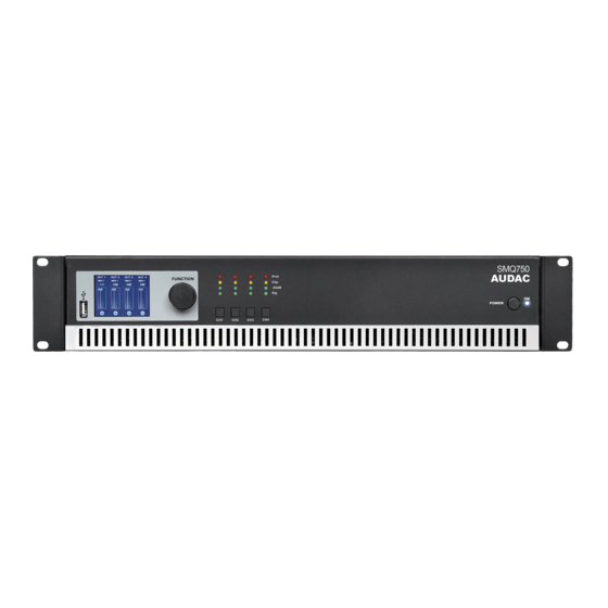
- Page 11 SMQ Series Front panel description The front panel of all SMA/SMQ amplifiers is almost identical, with few minor differences between the different models. The SMA series amplifiers (2-channel versions) only have two output selection buttons, while the SMQ series amplifiers (4-channel versions) have four. Other provided features such as USB port, LCD display and rotary selection dial are identical for all models.
- Page 12 Power switch A power switch allows to switch the amplifier on and off, while the blue indicator LED located next to the button illuminates when the power is switched on. Rear Panel overview SMA Series SMQ Series...
- Page 13 Rear panel description The rear panel of all SMA/SMQ amplifiers is almost identical, with few minor differences between the different models. The SMA series amplifiers (2-channel versions) have two inputs and two outputs, while the SMQ series amplifiers (4-channel versions) have four. Other provided connectivities such as RS-232 and power are identical for all models.
-
Page 14: Chapter 5: Configuring The Amplifier
1) Configuration using presets In case your setup is a pre-defined set solution from AUDAC, a set solution configuration file will be available (*.SOL) whereby all settings for the configuration can be made by uploading the corresponding file to the amplifier. - Page 15 3) Configuring the inputs After the output configuration has been made, the next step is the input configuration. In standard configuration, every output channel is patched with the corresponding input channel (Input 1 to Output 1, ... ). In case this configuration is required for your setup, this step can be skipped. In cases where specific inputs should be assigned to the outputs, the input selection can be made in the settings menu under ‘Settings’...
- Page 16 Chapter 4 Connecting the Amplifier NOTE Make sure the power is switched OFF when any change is made to the connections of the amplifier. Input connections The signal input connections are performed using a balanced XLR and 3-pin terminal block (3.81 mm pitch) connector for every input.
- Page 17 The used speaker connectors are 4-pole types, containing the output signal for the corresponding channel on +1/-1 terminals. The speaker connector for the first (and third for SMQ) channel also contains the output signal for the subsequent channel on +2/-2 terminals. This allows to transfer of two amplifier channels over one four-conductor loudspeaker cable which is fitted with one connector.
- Page 18 +1 and +2 terminals of the channel 1 (or channel 3 for SMQ). When using terminal blocks, connections are made between both + terminals. Selection for bridged output channels is made through software configuration by the user interface which is controllable using the front panel controls.
- Page 19 ATTENTION Do not connect any conventional 100 Volt line transformers directly to the loudspeaker outputs, an integrated decoupling network shall be provided when used in combination with line transformers. Wire up the system The wiring of the system must be done according to the following rules, to guarantee a proper functioning of the system in all circumstances.
- Page 20 Chapter 5 Configuring the amplifier The configuration of the amplifier can be done using the controls on the front panel of the amplifier. A graphical user interface is indicated on the front panel LCD display which guarantees an intuitive and user friendly experience.
-
Page 21: Main Screen
The main screen gives a fader overview for the output channels of the amplifier. Depending the channels for the corresponding model (two for SMA or four for SMQ), the output level for each channel can be adjusted. On top of the screen, the names of the output channels are shown (OUT 1, OUT 2, …... -
Page 22: Input
Input The input which is linked to every channel can be selected in this screen. Every input signal can be linked to every output channel, using the input selection matrix. Summed inputs for two sequent input channels can be selected too (E.g. Input 1+2). This can be useful when stereo input channels need to be patched to a mono output, or when the amplifier is used in bridge mode. -
Page 23: Equalizing
reached. After the desired frequency has been selected it can be confirmed by pressing (turns orange) and turning the function dial clockwise to the entire right side where the ‘OK’ word will appear. After pressing again the frequency is confirmed and the next characteristic can be adjusted. If all characteristics are set to the required value, select the ‘BACK’... -
Page 24: Max Level
Output setup >> Max level This function will guarantee that the output level adjustable by the fader on the main screen (which is accessible through user level access) will never exceed a certain value as configured. This gives protection for non-authorized persons when increasing the volume. It can be adjusted within a range of 0 dB (no restrictions) and -70 dB. -
Page 25: Bridge
Pairs of two subsequent channels can be bridged with merged power of both channels obtaining one single channel with double output power. The bridged pairs should always be subsequent channels (OUT 1+OUT2 & OUT3+OUT4 for SMQ). When bridging two channels, only one fader for the bridged channel will be shown in the main screen. -
Page 26: Input Gain
General setup >> Input gain The gain for each individual input can be set in this screen between a range of -16.5 dB and +30.75 dB. After scrolling and selecting the right input, gain can be adjusted through turning the rotary selection dial. - Page 27 After the desired file has been found, it can be loaded by selecting it. Speaker presets are files in *.SPF format which are prepared and provided by AUDAC and containing all parameters for optimal performance and protection for the corresponding loudspeaker.
-
Page 28: Info
General setup >> USB >> Key A USB key with both administrator and user level access can be created when selecting the corresponding buttons. A file containing the configured password information will be stored to the inserted medium, providing instant access to the functions when the medium is inserted. -
Page 29: Chapter 6: Additional Information
Chapter 6 Additional information Technical specifications RMS Output Power SMA350 4 Ohm Stereo 2 x 350 Watt (1 kHz, THD 1%) 8 Ohm Stereo 2 x 220 Watt 8 Ohm Bridge 700 Watt SMA500 4 Ohm Stereo 2 x 500 Watt 8 Ohm Stereo 2 x 300 Watt 8 Ohm Bridge... - Page 30 2-pin Terminal Block ~ 5.08 mm Controls DSP configuration via front panel RS-232 Indicators Power Protect Peak -20 dB Signal Protection DC-Short Circuit Over Heating Over Load Limiter Cooling system Temperature controlled fan Amplifier technology Class-D Power supply Type Switching mode Range 230~240 V AC / 50 Hz Power consumption...
- Page 31 Notes...
- Page 32 Notes...
Need help?
Do you have a question about the SMQ and is the answer not in the manual?
Questions and answers